Note: Descriptions are shown in the official language in which they were submitted.
CA 02886386 2015-03-26
WO 2014/052542 PCT/US2013/061848
Title
_
REVERSIBLE RATCHETING TOOL WITH DUAL PAWLS
Field of the Invention
[0001] The present invention relates generally to hand tools. More
particularly, the
present invention relates to a wrench that includes a ratcheting feature.
Background
[0002] Ratcheting tools, for example ratchets and wrenches, often include
a generally
cylindrical ratchet gear and a pawl that controls the gear's ratcheting
direction so that the gear
may rotate in one direction but is prevented from rotation in the other. It is
often desirable to
utilize ratchet wrenches in environments, such as an engine compartment of an
automobile,
where space restrictions limit the ability to adequately rotate a standard
wrench and, therefore,
fastener. As well, ratchet wrenches are desirable wherein removal and
reapplication of a
standard wrench to a fastener are similarly limited.
[0003] Even with the advantages offered by known ratchet wrenches, it is
not
uncommon for the ratchet wrenches to be used in situations where there is
insufficient
clearance to fully rotate the wrench and obtain an effective ratcheting action
for either
tightening or loosening a fastener. In order to overcome this problem, ratchet
wrenches with a
greater number of teeth on the gear, and corresponding pawl, have been
utilized. This reduces
the back swing arc and permits use of the wrench in more confined spaces.
However, the
greater number of teeth results in a plurality of thinner (or fine) teeth,
each of which has
CA 02886386 2015-03-26
WO 2014/052542 PCT/US2013/061848
reduced mechanical strength than the thicker teeth on a standard ratchet. As
such, there is a
greater possibility of damage to the fine teeth.
[0004] The present disclosure recognizes and addresses considerations of
prior art
constructions and methods.
Summary of the Disclosure
[0005] One embodiment of a ratcheting tool in accordance with the present
disclosure
includes a head and a handle attached to the head, and a gear ring disposed in
the head and
defining a first plurality of teeth about an outer circumference of the gear
ring so that the first
plurality of teeth define a first arc having a first radius. A first pawl is
disposed in the head so
that the first pawl is slidable laterally with respect to a longitudinal
center axis of the handle
between a first position in which the first pawl is disposed between the head
and the gear ring
so that the head transmits torque through the first pawl in a first rotational
direction, and a
second position in which the first pawl is disposed between the head and the
gear ring so that
the head transmits torque through the first pawl in an opposite second
rotational direction. The
first pawl defines a front face and a rearward face extending between an upper
surface and a
lower surface of the first pawl, and a second plurality of teeth on the front
face of the first
pawl for engaging the first plurality of teeth, the front face being concave
so that the second
plurality of teeth defines a second arc having a second radius. A second pawl
is disposed in
the head so that the second pawl is slidable laterally with respect to a
longitudinal center axis
of the handle between a first position in which the second pawl is disposed
between the head
and the gear ring so that the head transmits torque through the second pawl in
the first
rotational direction, and a second position in which the second pawl is
disposed between the
head and the gear ring so that the head transmits torque through the second
pawl in the
2
CA 02886386 2015-03-26
WO 2014/052542 PCT/US2013/061848
opposite second rotational direction. The second pawl defines a front face and
a rearward face
extending between an upper surface and a lower surface of the second pawl, and
a third
plurality of teeth on the front face of the second pawl for engaging the first
plurality of teeth,
the front face being concave so that the third plurality of teeth defines a
third arc having a third
radius. When the first pawl and the second pawl are disposed with the rearward
faces of the
first pawl and the second pawl in vertical alignment so that the longitudinal
center axes of the
first pawl and the second pawl are disposed in a common plane, the second arc
of the first
pawl is offset from the third arc of the second pawl in a direction that is
parallel to the
longitudinal center axes of the first pawl and the second pawl.
[0006] An alternate embodiment of a ratcheting tool in accordance with
the present
disclosure includes a head and a handle attached to the head, and a gear ring
disposed in the
head and defining a first plurality of teeth about an outer circumference of
the gear ring. A
first pawl is disposed in the head so that the first pawl is slidable
laterally and longitudinally
with respect to a longitudinal center axis of the handle between a first
position in which the
first pawl is disposed between the head and the gear ring so that the head
transmits torque
through the first pawl in a first rotational direction, and a second position
in which the first
pawl is disposed between the head and the gear ring so that the head transmits
torque through
the first pawl in an opposite second rotational direction. The first pawl
defines a front face and
a rearward face extending between an upper surface and a lower surface of the
first pawl, and
a second plurality of teeth on the front face of the first pawl for engaging
the first plurality of
teeth, the front face being concave. A second pawl is disposed in the head so
that the second
pawl is slidable laterally and longitudinally with respect to a longitudinal
center axis of the
handle between a first position in which the second pawl is disposed between
the head and the
3
CA 02886386 2015-03-26
WO 2014/052542 PCT/US2013/061848
gear ring so that the head transmits torque through the second pawl in the
first rotational
direction, and a second position in which the second pawl is disposed between
the head and the
gear ring so that the head transmits torque through the second pawl in the
opposite second
rotational direction. The second pawl defines a front face and a rearward face
extending
between an upper surface and a lower surface of the second pawl, and a third
plurality of teeth
on the front face of the second pawl for engaging the first plurality of
teeth, the front face
being concave. When the first pawl and the second pawl are disposed with the
rearward faces
of the first pawl and the second pawl in vertical alignment so that the
longitudinal center axes
of the first pawl and the second pawl are disposed in a common plane, the
second plurality of
teeth of the first pawl is offset from the third plurality of teeth of the
second pawl in a direction
that is parallel to the longitudinal center axes of the first pawl and the
second pawl.
[0007] The accompanying drawings, which are incorporated in and
constitute a part of
this specification, illustrate one or more embodiments of the disclosure and,
together with the
description, serve to explain the principles of the various embodiments.
Brief Description of the Drawings
[0008] A full and enabling disclosure of the present disclosure,
including the best mode
thereof, directed to one of ordinary skill in the art, is set forth in the
specification, which
makes reference to the appended drawings, in which:
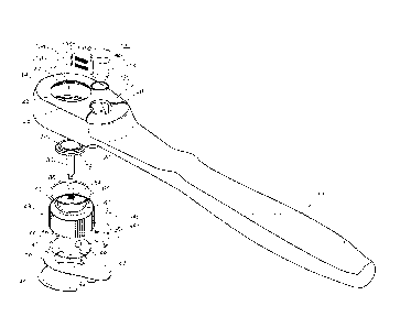
[0009] Figure 1 is a perspective view of a ratcheting tool in accordance
with an
embodiment of the present disclosure;
[0010] Figure 2 is an exploded view of the ratcheting tool as in Figure
1;
[0011] Figure 3A is a sectional view of the body of ratcheting tool as in
Figure 1;
[0012] Figure 3B is a partial sectional view of the ratcheting tool as in
Figure 1;
4
CA 02886386 2015-03-26
WO 2014/052542 PCT/US2013/061848
[0013] Each of Figures 4A through 4D is a top view, partly in section, of
the ratcheting
tool as in Figure 1;
[0014] Each of Figures 5A through 5D is an elongated view of a portion of
the
components shown in Figure 4;
[0015] Figure 6A is a top view of a ratchet gear and release button of
the ratcheting
tool as in Figure 1;
[0016] Each of Figures 6B and 6C is a side view, partly in section, of
the ratchet gear
and release button as in Figure 6A;
[0017] Figure 7 is a top view of a lower pawl of a ratcheting tool as in
Figure 1;
[0018] Figure 8 is a perspective view of the lower pawl as in Figure 7;
[0019] Figure 9 is a top view of an upper pawl of a ratcheting tool as in
Figure 1;
[0020] Figure 10 is a perspective view of the upper pawl as in Figure 9;
[0021] Figure 11 is a top view of the reversing lever of the ratcheting
tool shown in
Figure 1;
[0022] Figure 11A is a partial side view, in section, of the reversing
lever of Figure 11;
[0023] Figure 12 is a bottom view, partly in section, of the reversing
lever shown in
Figure 11;
[0024] Figure 13 is an exploded view of the reversing lever shown in
Figure 11;
[0025] Figure 14 is a side view of a lower pusher as shown in Figure 13;
[0026] Figure 14A is a cross-sectional view of the lower pusher shown in
Figure 14;
[0027] Figure 15 is a front view of the lower pusher shown in Figure 14;
[0028] Figure 16 is a top view of the upper and the lower pawls of the
ratcheting tool
shown in Figure 1, in a stacked configuration;
CA 02886386 2015-03-26
WO 2014/052542 PCT/US2013/061848
[0029] Figure 17 is a top view of a lower pawl of a ratcheting tool in
accordance with
an alternate embodiment of the present disclosure;
[0030] Figure 18 is a perspective view of the lower pawl as in Figure 17;
[0031] Figure 19 is a top view of an upper pawl of a ratcheting tool in
accordance with
an alternate embodiment of the present disclosure;
[0032] Figure 20 is a perspective view of the upper pawl as in Figure 19;
and
[0033] Figure 21 is a top view of the upper and lower pawls, as shown in
Figures 17
and 19, respectively, in a stacked configuration.
[0034] Repeat use of reference characters in the present specification
and drawings is
intended to represent same or analogous features or elements of the invention.
Detailed Description
[0035] Reference will now be made in detail to various embodiments of the
invention,
one or more examples of which are illustrated in the accompanying drawings.
Each example is
provided by way of explanation of the invention, not limitation of the
invention. In fact, it will
be apparent to those skilled in the art that modifications and variations can
be made in the
present invention without departing from the scope and spirit thereof. For
instance, features
illustrated or described as part of one embodiment may be used on another
embodiment to
yield a still further embodiment. Thus, it is intended that the present
invention covers such
modifications and variations as come within the scope of the appended claims
and their
equivalents.
[0036] Referring to Figure 1, a ratcheting tool 10 includes an elongated
arm, which
may be formed as a handle 12 from stainless steel, metal alloys or other
suitable materials.
The length of handle 12 may vary depending on the application of ratcheting
tool 10. A head
6
CA 02886386 2015-03-26
WO 2014/052542 PCT/US2013/061848
14 extends from the handle 12, and the head and handle may be integrally
formed from the
same material.
[0037] Referring to Figures 2, 3A, and 3B, head 14 defines a relatively
large and
generally cylindrical through-hole compartment 16. A web portion 20 is
intermediate to head
14 and handle 12 and defines a smaller, wedge-shaped compartment 18 (see also
Figures 4A
and 4B). A generally cylindrical compartment 24 extends through a top face 22
into web 20 at
a hole 26 and overlaps compartment 18. Compartment 18 is closed above by top
face 22 and
opens into both compartments 16 and 24. The underside of head 14 is open and
receives a
cover 28 that secures certain components of ratcheting tool 10 within
compartments 16, 18,
and 24, as described in greater detail below.
[0038] A wall 30 defines compartment 16 between a radially outward
extending ledge
32 at one end and a radially inward extending ledge 34 at its other end. An
annular groove 36
is defined in a vertical wall extending down from ledge 32 and surrounding
most of
compartment 16.
[0039] Cover 28 has an annular portion 40 defining a hole 42 and a tab
portion 44
extending from annular portion 40. An opening 35 in the bottom of head 14 and
web 20
receives cover 28 so that annular portion 40 sits on ledge 32. Annular groove
36 receives a C-
clip 46 to secure cover 28 between the C-clip and ledge 32 so that cover 28 is
held in position
over compartments 16, 18, and 24.
[0040] Compartment 16 receives an annular gear ring 48 having an inner
surface 50
that is concentric with wall 30 of head 14. As shown in Figures 6A through 6C,
the outer
circumference of gear ring 48 defines an annular array of vertically-aligned
teeth 52. More
specifically, the embodiment shown preferably includes sixty (60) gear teeth
52 evenly spaced
7
CA 02886386 2015-03-26
WO 2014/052542 PCT/US2013/061848
about the outer surface of gear ring, meaning the gear ring 48 has an index of
60. The gear
ring's bottom side defines an extension portion 56 surrounded by a flat
annular shoulder 58
that defines an annular groove 60. On the top side, a top ledge 62 surrounds
an upwardly
extending wall 64. Gear ring 48 fits into compartment 16 so that wall 64
extends through a
hole 23 in top face 22 and so that ledge 62 abuts ledge 34. When cover 28 is
secured to head
14, extension portion 56 extends through hole 42. Circular portion 40 abuts
shoulder 58,
thereby retaining gear ring 48 in compartment 16.
[0041] Extension portion 56 and wall 64 fit through hole 42 and hole 23,
respectively,
with sufficient clearance so that the gear ring is secured in the radial
direction yet is permitted
to rotate with respect to head 14. A lower 0-Ring 66 is received in annular
groove 60 and
abuts cover 28, while an upper 0-ring extends around wall 64 between ledges 21
and 62. The
0-rings aid in smooth rotation of gear ring 48 and minimize the amount of dirt
and debris that
can enter compartment 16. 0-Rings 66 may be formed from pliable rubbers,
silicones, metals,
or other suitable material.
[0042] Extension portion 56 is square shaped in cross-section and is
adapted to receive
a standard three-eighths (3/8) inch drive socket, which should be well
understood in the art.
Extension 56 may also be sized to fit one-quarter (1/4) inch drive, one-half
(1/2) inch drive, or
other drive size sockets as desired.
[0043] Inner surface 50 of gear ring 48 surrounds a blind bore 68
centered around the
axis of gear ring 48. Bore 68 receives a push button 76 having an annular top
78 and a
cylindrical shaft 80. The top end of bore 68 defines a shoulder 82 that is
peened inward to
retain button 76 in the bore. A spring 84 and ball 86 in the bottom of bore 68
bias button 76
8
CA 02886386 2015-03-26
WO 2014/052542 PCT/US2013/061848
upward against shoulder 82. A cylindrical bore 90 intersects bore 68 at a
right angle and
receives a ball 92. An edge 88 is peened inward to retain the ball in the
bore.
[0044] Ball 86 controls the position of ball 92 within bore 90. Normally,
when spring
84 and ball 86 push the top of button 76 up against shoulder 82, ball 86 is
aligned with ball 92,
thereby pushing ball 92 out against edge 88 of bore 90. In this position, a
portion of ball 92
extends out of bore 90 to retain a socket on extension 56. To remove the
socket, the operator
pushes push button 76 down against spring 84. This moves ball 86 below bore 90
and aligns a
narrowed end of shaft 80 with ball 92, thereby allowing ball 92 to move back
into bore 90 and
releasing the socket.
[0045] Referring to Figures 4A through 4D, compartment 18 receives a pair
of
generally wedge-shaped pawls, more specifically, a lower pawl 94a and an upper
pawl 94b, in
a stacked configuration between side walls 98 and 100. Cover 28 and top face
22 (Figure 2) of
web 20 retain lower and upper pawls 94a and 94b from below and above. Walls 98
and 100
are formed so that vertical planes (i.e. planes perpendicular to the page)
defined by the walls
intersect a vertical plane 99 that passes through the center of compartments
16 and 24 (see
Figures 2 and 3A) at an angle such that compartment 18 optimizes the load-
bearing and
ratcheting capabilities of ratcheting tool 10. The size of the angle may vary
depending on the
tool's intended use. A larger angle, for example, allows for greater load-
carrying
characteristics between lower and upper pawls 94a and 94b and gear ring 48,
while a smaller
angle provides for better ratcheting and reversing. Thus, the angle chosen in
a given instance
preferably provides the best combination of gear/pawl tooth loading and
clearance for the
pawls during ratcheting and reversing. In a preferred embodiment, the angle
between plane 99
9
CA 02886386 2015-03-26
WO 2014/052542 PCT/US2013/061848
and each of side walls 98 and 100 is 31 degrees and is preferably within a
range of 27 degrees
to 35 degrees.
[0046] As shown in Figures 7 and 8, lower pawl 94a defines a plurality of
vertically-
aligned teeth 102 across the pawl's front face in an arc having a radius Rl.
In the illustrated
embodiment, lower pawl includes eleven teeth 102, the tips of the teeth are
rounded slightly,
and R1 is measured to the rounded tips of the teeth. The radius R1 is the same
as a radius R2
(Figure 6A) between the center 68 of gear ring 48 and the troughs of its teeth
52. Because of
manufacturing tolerances, the tips of the pawl teeth and the troughs of the
gear teeth vary
slightly in the radial direction, as should be understood in this art. Thus,
radii R1 and R2
should be understood to lie within the pawl and gear tolerance ranges and are
assumed to
extend to the mid-points of the respective tolerance range for purposes of
this discussion.
Furthermore, it should be understood that radii R1 and R2 may be taken at
other locations on
the gear and the pawl, for example at the tips of the gear teeth and the
troughs of the pawl
teeth. As well, in the embodiment shown, teeth 102 are evenly spaced on the
pawl's front face
so that lower pawl 94a has the same index, that being 6 , as the gear teeth
52.
[0047] The rearward face 93 of lower pawl 94a defines a pocket 104 having
two curved
portions 108 and 110 separated by a bridge 112 and having symmetric rearwardly-
extending
sides 114 and 116. A notch 118 extends into the back end of lower pawl 94a
from a bottom
surface 120. The remainder of rearward face 93 of lower pawl 94a is defined by
first and
second smooth, continuous portions 93a and 93b disposed on opposite sides of
pocket 104.
[0048] As shown in Figures 9 and 10, upper pawl 94b defines a plurality
of vertically-
aligned teeth 102 across the pawl's front face in an arc having a radius Rl.
In the illustrated
embodiment, upper pawl includes ten teeth 102, the tips of the teeth are
rounded slightly, and
CA 02886386 2015-03-26
WO 2014/052542 PCT/US2013/061848
R1 is measured to the rounded tips of the teeth. The radius R1 is the same as
a radius R2
(Figure 6A) between the center 68 of gear ring 48 and the troughs of its teeth
52. Similarly to
lower pawl 94a, because of manufacturing tolerances, the tips of the pawl
teeth and the troughs
of the gear teeth vary slightly in the radial direction, as should be
understood in this art. Thus,
radii R1 and R2 should be understood to lie within the pawl and gear tolerance
ranges and are
assumed to extend to the mid-points of the respective tolerance range for
purposes of this
discussion. Furthermore, it should be understood that radii R1 and R2 may be
taken at other
locations on the gear and the pawl, for example at the tips of the gear teeth
and the troughs of
the pawl teeth. As well, in the embodiment shown, teeth 102 are evenly spaced
on the pawl's
front face so that upper pawl 94b has the same index, that being 60, as the
gear teeth 52.
[0049] Additionally, rearward face 93 of upper pawl 94b defines a pocket
104 having
two curved portions 108 and 110 separated by a bridge 112 and having symmetric
rearwardly-
extending sides 114 and 116. Similarly to lower pawl 94a, the remainder of
rearward face 93
of upper pawl 94b is defined by first and second smooth, continuous portions
93a and 93b
disposed on opposite sides of pocket 104. Preferably, first and second
portions 93a and 93b of
upper pawl's rearward face 93 are formed identically to first and second
portions 93a and 93b
of lower pawl's rearward face 93.
[0050] Referring now to Figure 16, a top view of upper and lower pawls
94b and 94a
in a stacked configuration is provided in which the rearward faces, more
specifically, first and
second portions 93a and 93b of each rearward face, of upper pawl 94b and lower
pawl 94a,
are vertically aligned. As well, the pawls are positioned such that their
longitudinal center
axes lie in a common vertical plane. As previously discussed, gear ring 48
preferably defines
60 gear teeth 52 evenly spaced about its outer circumference, meaning the
teeth are disposed
11
CA 02886386 2015-03-26
WO 2014/052542 PCT/US2013/061848
every 6 . Similarly, teeth 102 of lower pawl 94a and upper pawl 94b are
disposed along their
respective front faces at 6 increments. Note, however, that when their
longitudinal center
axes are aligned, teeth 102 of lower pawl 94a are circumferentially offset
from teeth 102 of
upper pawl 94b by approximately one-half pitch, meaning by approximately 3 in
the present
case. As discussed in greater detail below, the effect of the circumferential
offset of the pawl
teeth is equivalent to doubling the number of gear teeth 52 from 60 teeth to
120 teeth. As
such, the ratcheting index of the wrench is decreased from approximately 6 to
approximately
30.
[0051] Still referring to Figure 16, in the embodiment shown, an arc
defined by teeth
102 of lower pawl 94a is offset from an arc defined by teeth 102 of upper pawl
94b in a
direction that is parallel to the longitudinal center axes of the pawls. In
short, the net effect of
the offset is that the pawl having the fewer number of teeth, that being upper
pawl 94b, is
"thicker" than the lower pawl 94a in a direction parallel to the longitudinal
center axes of the
pawl. As shown, the offset (X) is preferably between approximately 0.002 to
0.008 inches,
most preferably being approximately 0.005 inches.
[0052] Referring to Figures 11, 11A, 12 and 13, a reversing lever 122
includes a
handle portion 124 and a bottom portion 126. The outer surface of bottom 126
defines an
annular groove 128 that receives an 0-ring 130, which extends slightly outward
of groove 128.
Groove 128 is located proximate handle portion 124 such that an annular shelf
132 extends
between groove 128 and the front of handle 124. Bottom 126 defines a lower
blind bore 134a
and an upper blind bore 134b that receive a lower spring 136a and pusher 138a,
and an upper
spring 136b and pusher 138b, respectively. Referring to Figures 14, 14A and
15, lower
pusher 138a is cylindrical in shape and defines a blind bore 140 in its rear
end and a rounded
12
CA 02886386 2015-03-26
WO 2014/052542 PCT/US2013/061848
front end 142. Bore 140 is adapted to receive lower spring 136a so that the
spring biases
lower pusher 138a radially outward from bore 134. Upper spring 136b and upper
pusher 138b
are identical in construction to lower spring 136a and lower pusher 138a.
[0053] Referring to Figures 2, 3B, 11A and 13, hole 26 in web 20 receives
the lever's
bottom portion 126. The diameter of bottom portion 126 is approximately equal
to the
diameter of hole 26, although sufficient clearance is provided so that the
reversing lever rotates
easily in the hole. Upon insertion of bottom portion 126 into hole 26, the
hole's side pushes
0-ring 130 radially inward into groove 128 so that the 0-ring thereafter
inhibits the entrance of
dirt into the compartment. Referring also to Figure 7, lower pusher 138a
extends into pocket
104 of lower pawl 94a and engages curved portions 108 and 110 and sides 114
and 116,
depending on the position of the pawl and lever. Similarly, upper pusher 138b
extends into
pocket 104 of upper pawl 94b and engages curved portion 108 and 110 and sides
114 and 116,
depending on the position of the pawl and lever. A radially outward extending
lip 144 at the
bottom of the lever fits into notch 118 in the pawl, and a lip 145 extends
into a groove at the
bottom of compartment 24, thereby axially retaining lever 122 its compartment.
[0054] In operation, as shown in Figures 4A and 4B, lower and upper pawls
94a and
94b may slide to either side of compartment 18 laterally with respect to the
gear between two
positions in which the pawl is wedged between the body and the gear. In Figure
4B, lever 122
is rotated to its most clockwise position, and both lower pawl 94a and upper
pawl 94b are
wedged between gear ring 48 and top side 98 of compartment 18. Lower and upper
springs
136a and 136b push lower and upper pushers 138a and 138b, respectively,
forward so that the
pushers' front ends 142 engage the respective pocket sides 114 and thereby
bias the respective
pawls to the wedged position. Note, Figure 4B shows the positions of upper and
lower pawls
13
CA 02886386 2015-03-26
WO 2014/052542 PCT/US2013/061848
94a and 94b relative to gear ring 48 at the onset of the ratcheting process.
As such, the faces
and, therefore, teeth 102 of upper and lower pawls 94a and 94b, are disengaged
from gear
teeth 52 as the pawls are pivoted away from the gear about their outermost
teeth 102a and
102b, as discussed in greater detail below. However, if torque is applied to
handle 12 (Figure
2) in the clockwise direction when a socket on the gear extension engages a
work piece, the top
side of compartment 18 pushes pawl teeth 102 of the lower and upper pawls 94a
and 94b
against opposing gear teeth 52 as best seen in Figure 4D. As shown, during
application of
torque, upper and lower pawls 94a and 94b pivot inwardly towards gear ring 48,
with lower
pawl 94a, in the instant case, being fully engaged with the gear ring. That
is, the pawls
remain wedged between the gear ring and the compartment's top edge, and the
force applied
from the operator's hand to the pawl through top side 98 is therefore applied
in the clockwise
direction to the work piece through gear ring 48. Figure 4C shows the
application of torque to
a fastener when lever 122 is rotated in its most counter-clockwise position
and both lower and
upper pawls 94a and 94b are wedged between gear ring 48 and bottom side 100 of
compartment 18.
[0055] Referring additionally to Figures 5A through 5D, if an operator
applies torque
to the handle in the counter-clockwise direction, gear teeth 52 apply a
counterclockwise
reaction force to lower and upper pawls 94a and 94b. As best seen in Figure
5A, at the onset
of the ratcheting process, an outermost tooth 102a of bottom pawl 94a is fully
seated between
gear teeth 52a and 52b, whereas the tip of an outermost tooth 102b of upper
pawl 94b is
disposed at approximately the midpoint of a leading edge 53 of gear tooth 52a.
If gear ring 48
remains rotationally fixed to a work piece through a socket, gear teeth 52
hold the pawls so
that the pawls pivot slightly relative to gear ring 48 in from the top end of
the pawl (as viewed
14
CA 02886386 2015-03-26
WO 2014/052542 PCT/US2013/061848
in Figure 4B) and moves back and down into compartment 18. As the operator
applies
increasing torque to the handle, the torque eventually overcomes the biasing
force of springs
136a and 136b. This causes pawl pocket sides 114 (Figures 7 and 8) of both
lower and upper
pawls 94a and 94b to push back against the respective pusher tips 142 and the
force of the
corresponding springs. Eventually, outermost teeth 102a and 102b of lower and
upper pawls
94a and 94b, respectively, begin to slide radially outward along leading edges
53 of gear teeth
52b and 52a, respectively. Springs 136a and 136b continue to bias lower and
upper pushers
138a and 138b, respectively, forward against sides 114 of their respective
pawl pockets 104,
forcing both pawls back up toward the top face of compartment 18. As such,
lower and upper
pawls 94a and 94b maintain contact with side wall 98 of compartment 18 while
ratcheting
occurs. As previously noted, the pitch of both the gear teeth and pawl teeth
in the present
embodiment is 6 . As such, a rotation of 6 of the wrench handle is required
for both
outermost teeth 102a and 102b to move from one trough between consecutive gear
teeth to the
next.
[0056] Figure 5B shows the disposition of outermost teeth 102a and 102b
after the
wrench handle has been rotated through approximately 2 in the counter-
clockwise direction.
As shown, tooth 102a of lower pawl 94a has slid outwardly along a portion of
leading edge 53
of gear tooth 52b. Similarly, tooth 102b of upper pawl 94b has slid outwardly
along leading
edge 53 of gear tooth 52a. Note, however, that tooth 102b is disposed near the
outermost tip
of gear tooth 52a since it started at a position half-way along the leading
edge of gear tooth 52a
at the onset of the ratcheting process.
[0057] As shown in Figure 5C, after rotation of the wrench handle through
3 in the
counter-clockwise direction, tooth 102b of upper pawl 94b has cleared gear
tooth 52a and is
CA 02886386 2015-03-26
WO 2014/052542 PCT/US2013/061848
fully seated in the adjacent gear tooth trough. As such, the torque wrench has
an effective
ratcheting index of 3 between torque-applying configurations. As shown, tooth
102a of lower
pawl 94a continues to slide outwardly along gear tooth 52b, with both teeth
102a and 102b
being disposed in the same gear tooth trough.
[0058] Referring now to Figure 5D, the wrench handle has been rotated
through 5 in
the counter-clockwise direction. As such, tooth 102a has slid outwardly along
almost the
entire length of gear tooth 52b. As well, tooth 102b has begun to slide
outwardly along
leading edge 53 of tooth 52b. Further rotation of the wrench handle, more
specifically,
approximately 1 so that the entire rotation is approximately 6 from the
onset, results in tooth
102a of lower pawl 94a clearing gear tooth 52b and being fully seated in the
adjacent trough.
[0059] To change the operative direction of ratcheting tool 10, the
operator rotates
switch 122 in the counterclockwise direction. Lever bottom portion 126 (Figure
2) rotates in
hole 26, and the pushers move counterclockwise in the corresponding pawl
pockets through
curved portions 108 toward bridges 112 (Figures 7 and 9). Initially, the pawls
pivot slightly,
and the load-bearing pawl teeth of each pawl move away from the gear teeth. As
the pushers
move toward the corresponding bridges, each pawl begins to shift down and back
in
compartment 18. Further rotation brings the pushers into contact with the
corresponding
bridge, causing the pawl teeth to ride down and back into compartment 18 over
the gear teeth.
Gear ring 48 may also rotate slightly. In this position, lower and upper pawls
94a and 94b
move the pushers back against the force of the springs. As the operator
continues to rotate
switch 122, the pushers move into the corresponding curved portions 110 and
push forward
against the corresponding walls 116. This applies a counterclockwise force to
each pawl so
that each pawl moves downward in compartment 18 and wedges between the gear
ring and the
16
CA 02886386 2015-03-26
WO 2014/052542 PCT/US2013/061848
compartment's bottom edge 100. When the pawls have moved over to this wedged
position,
the configuration and operation of the gear, the pawl, and the lever mirror
the pawl's operation
described above with respect to Figure 4B. That is, the tool ratchets and
applies torque to a
work piece in the same manner but in the opposite direction.
[0060] As shown in Figures 17 and 18, a lower pawl 94a in accordance with
an
alternate embodiment of the present disclosure defines a plurality of
vertically-aligned teeth
102 across the pawl's front face, wherein the front face is formed by two arc
portions rather
than one. As shown, both an upper arc portion 95a, disposed above the
longitudinal center
axis of the pawl, and a lower arc portion 95b, disposed below the longitudinal
center axis of
the pawl, have a radius of Rl. Note, however, that the center of curvature of
both upper arc
portion 95a and lower arc portion 95b are offset above and below,
respectively, the
longitudinal center axis. As such, the arc portions do not form one continuous
arc, but rather,
two portions that intersect at the longitudinal center axis as shown.
[0061] In the illustrated embodiment, lower pawl 94a includes eleven
teeth 102, the tips
of the teeth are rounded slightly, and R1 is measured to the rounded tips of
the teeth. The
radius R1 of each arc portion is the same as a radius R2 (Figure 6A) between
the center 68 of
gear ring 48 and the troughs of its teeth 52. Because of manufacturing
tolerances, the tips of
the pawl teeth and the troughs of the gear teeth vary slightly in the radial
direction, as should
be understood in this art. Thus, radii R1 and R2 should be understood to lie
within the pawl
and gear tolerance ranges and are assumed to extend to the mid-points of the
respective
tolerance range for purposes of this discussion. Furthermore, it should be
understood that
radii R1 and R2 may be taken at other locations on the gear and the pawl, for
example at the
tips of the gear teeth and the troughs of the pawl teeth. As well, in the
embodiment shown,
17
CA 02886386 2015-03-26
WO 2014/052542 PCT/US2013/061848
teeth 102 are evenly spaced on the pawl's front face so that both the upper
and lower arc
portions 95a and 95b of lower pawl 94a have the same index, that being 60, as
the gear teeth
52.
[0062] The rearward face 93 of lower pawl 94a defines a pocket 104 having
two curved
portions 108 and 110 separated by a bridge 112 and having symmetric rearwardly-
extending
sides 114 and 116. A notch 118 extends into the back end of lower pawl 94a
from a bottom
surface 120. The remainder of rearward face 93 of lower pawl 94a is defined by
first and
second smooth, continuous portions 93a and 93b disposed on opposite sides of
pocket 104.
[0063] As shown in Figures 19 and 20, upper pawl 94b of the alternate
embodiment
defines a plurality of vertically-aligned teeth 102 across the pawl's front
face, wherein the front
face is formed by two arc portions rather than one. As shown, both an upper
arc portion 97a,
disposed above the longitudinal center axis of the pawl, and a lower arc
portion 97b, disposed
below the longitudinal center axis of the pawl, have a radius Rl. Note,
however, that the
center of curvature of both upper arc portion 97a and lower arc portion 97b
are offset above
and below, respectively, the longitudinal center axis. As such, the arc
portions do not form
one continuous arc, but rather, two portions that intersect at the
longitudinal center axis as
shown.
[0064] In the illustrated embodiment, upper pawl 94b includes ten teeth
102, the tips of
the teeth are rounded slightly, and R1 is measured to the rounded tips of the
teeth. The radius
R1 is the same as a radius R2 (Figure 6A) between the center 68 of gear ring
48 and the
troughs of its teeth 52. Similarly to lower pawl 94a, because of manufacturing
tolerances, the
tips of the pawl teeth and the troughs of the gear teeth vary slightly in the
radial direction, as
should be understood in this art. Thus, radii R1 and R2 should be understood
to lie within the
18
CA 02886386 2015-03-26
WO 2014/052542 PCT/US2013/061848
pawl and gear tolerance ranges and are assumed to extend to the mid-points of
the respective
tolerance range for purposes of this discussion. Furthermore, it should be
understood that
radii R1 and R2 may be taken at other locations on the gear and the pawl, for
example at the
tips of the gear teeth and the troughs of the pawl teeth. As well, in the
embodiment shown,
teeth 102 are evenly spaced on the pawl's front face so that upper pawl 94b
has the same
index, that being 6 , as the gear teeth 52.
[0065] Additionally, rearward face 93 of upper pawl 94b defines a pocket
104 having
two curved portions 108 and 110 separated by a bridge 112 and having symmetric
rearwardly-
extending sides 114 and 116. Similarly to lower pawl 94a, the remainder of
rearward face 93
of upper pawl 94b is defined by first and second smooth, continuous portions
93a and 93b
disposed on opposite sides of pocket 104. Preferably, first and second
portions 93a and 93b of
upper pawl's rearward face 93 are formed identically to first and second
portions 93a and 93b
of lower pawl's rearward face 93.
[0066] Referring now to Figure 21, a top view of upper and lower pawls
94b and 94a
in a stacked configuration is provided in which the rearward faces, more
specifically, first and
second portions 93a and 93b of each rearward face, of upper pawl 94b and lower
pawl 94a,
are vertically aligned. As well, the pawls are positioned such that their
longitudinal center
axes lie in a common vertical plane. As previously discussed, gear ring 48
preferably defines
60 gear teeth 52 evenly spaced about its outer circumference, meaning the
teeth are disposed
every 6 . Similarly, teeth 102 of lower pawl 94a and upper pawl 94b are
disposed along the
respective upper and lower arc portions of their front faces at 6 increments.
Note, however,
that when their longitudinal center axes are aligned, teeth 102 of lower pawl
94a are
circumferentially offset from teeth 102 of upper pawl 94b by approximately one-
half pitch,
19
CA 02886386 2015-03-26
WO 2014/052542 PCT/US2013/061848
meaning by approximately 30 in the present case. As previously discussed, the
effect of the
circumferential offset of the pawl teeth is equivalent to doubling the number
of gear teeth 52
from 60 teeth to 120 teeth. As such, the ratcheting index of the wrench is
decreased from
approximately 60 to approximately 30
.
[0067] Still referring to Figure 19, in the embodiment shown, upper and
lower arc
portions 95a and 95b defined by teeth 102 of lower pawl 94a are offset from
the corresponding
upper and lower arc potions 97a and 97b defined by teeth 102 of upper pawl 94b
in a direction
that is parallel to the longitudinal center axes of the pawls. In short, the
net effect of the offset
is that the pawl having the fewer number of teeth, that being upper pawl 94b,
is "thicker" than
the lower pawl 94a in a direction parallel to the longitudinal center axes of
the pawl. As
shown, the offset (X) is preferably between approximately 0.002 to 0.008
inches, most
preferably being approximately 0.005 inches.
[0068] The operation of the ratcheting tool including upper and lower
pawls 94a and
94b (as shown in Figures 17 through 21) is substantially the same as the
previously discussed
embodiment of the disclosed ratchet wrench. As such, a discussion of the
present embodiment
is not required here, and is omitted.
[0069] While one or more preferred embodiments of the invention have been
described
above, it should be understood that any and all equivalent realizations of the
present invention
are included within the scope and spirit thereof. The embodiments depicted are
presented by
way of example only and are not intended as limitations upon the present
invention. Thus, it
should be understood by those of ordinary skill in this art that the present
invention is not
limited to these embodiments since modifications can be made. For example, the
number of
gear teeth can be more or less than the disclosed 60 teeth, the number of
teeth on the pawls can
CA 02886386 2015-03-26
WO 2014/052542 PCT/US2013/061848
vary, the radius of curvature of the arc defined by the teeth on one or both
pawls can be
greater than or less than the radius of curvature of the gear teeth, the pawl
having the greater
number of teeth can be disposed on top of the pawl having fewer teeth, the
pawl having the
reduced number of teeth can be the "thinner" pawl in the direction parallel to
the longitudinal
center axes of the pawls, etc. Therefore, it is contemplated that any and all
such embodiments
are included in the present invention as may fall within the scope of the
appended claims.
21