Note: Descriptions are shown in the official language in which they were submitted.
CA 02886806 2015-03-31
Method for producing a one-piece lock striker
The invention relates to a method for producing a one-piece lock striker
according to the
generic part of claim 1 and a lock striker produced according to this method.
Said lock strikers can be found, in particular, in motor vehicle locks and
locking
mechanisms. Below, the invention is explained with reference to the area of
application
of the motor vehicle locks, although the invention is not restricted to this.
A lock striker usually comprises a base plate and a lock bracket, also
referred to as
locking bolt or lock striker bracket. The base plate typically contains
openings in form of
e.g. holes to allow, for instance fixing of the lock striker to the body of a
motor vehicle.
The lock bracket is shaped in such a way that it contains a centre opening so
that, when
installed, the lock bracket interacts with a lock or locking mechanism. The
lock striker
can thus, in the closed state of a motor vehicle door or flap be in a
retaining
engagement with a rotary latch of a lock or similar in order to securely close
a flap or
door of a vehicle.
A motor vehicle lock generally contains a locking mechanism comprising a
rotary latch
and at least one pawl by means of which a rotation of the rotary latch in
opening
direction can be blocked.
As a result of the engagement between the lock striker and the rotary latch
during the
closing operation but also during opening of the lock, a lock striker is
regularly exposed
to high stressing. This is, in particular, the case in the event of a crash,
resulting in
particularly severe deformation.
A one-piece lock striker is usually produced by solid forming of a starter
material ¨ i.e. a
blank ¨ by cold extrusion or cold upsetting. Publication DE 10 2007 041 479 Al
discloses a one-piece lock striker for a motor vehicle closing system, in form
of a solid
component with cross sections of different thicknesses in order to achieve a
better
production and improved mechanical characteristics.
1
CA 02886806 2015-03-31
Publication DE 10 2010 024 510 Al discloses a method for the production of a
lock
striker, in which raw material is first sheared off and is then heated to
processing
temperatures above the recrystallisation temperature for hot forming, after
which it is
formed into a lock striker by compressive forming using forging hammers.
Publication DE 10 2010 011 716 Al discloses a method for the production of a
lock
striker, in which a T-shaped semi-finished product is formed from a raw
material by cold
extrusion. The lock striker can be formed from a round raw material to a T-
shaped semi-
finished product by solid forming. The T-shaped semi-finished product is then,
for
instance, processed further by cold stamping, in order to provide fixing holes
in the base
plate and an opening in the lock bracket. The method is designed to save on
complex
reworking of the lock striker.
The as yet unpublished DE 10 2010 054 369 discloses a method for producing
lock
strikers, in which a T-shaped semi-finished product is formed by cold
extrusion and in
which subsequently fixing holes and openings are formed by stamping. In
addition, a
material bead is arranged on the leg of the lock bracket parallel to the base
plate in
order to produce a trailing edge during forming into a T-shaped semi-finished
product.
The trailing edge serves, in the first instance, to prevent a deformation and
catching of
the lock plate in the event of a crash so that a motor vehicle lock can still
be reliably
opened.
The forming process based on plastic changing of a specified solid starter
blank is
generally associated with the problem that considerable forming forces are
required,
which also considerably stress the tool. Furthermore, large machines such as
presses
are required for providing said considerable forming forces.
Unless specified differently below, the aforementioned characteristics can be
combined
individually or in any combination with the object of the invention described
below.
It is the task of the invention to further develop the production of a lock
striker.
The task of the invention is solved by a method with the characteristics of
claim 1.
Advantageous embodiments are disclosed in the sub claims.
2
CA 02886806 2015-03-31
According to the method of the invention, a lock striker is formed from a
metal starter
blank by cold forming and, in particular, cold upsetting. Prior to the forming
process, the
starter blank is essentially block-shaped or cylindrical and is formed in such
a way that
the lock striker is strain hardened.
Preferably the starter blank is formed to a shape closely representing the
final shape
during forming. The formed starter blank then essentially corresponds to the
final form
of the lock striker after the forming process. Openings such as holes in the
base plate
and the hole in the lock bracket can generally be produced during the forming
process
or during subsequent steps by stamping or cutting, as required.
A key element is forming of the starter blank to a one-piece lock striker from
an
essentially block-shaped or cylindrical starter blank to systematically form a
fit-for-
purpose lock striker that can also be easily produced. Using the suggested
method, the
mechanical characteristics of the lock striker can be specifically set to
provide very
specific application characteristics of a thus produced lock striker. Cold
forming causes
a further increase in strength also referred to as strain hardening.
Consequently,
materials can be used for the starter blank that in their original state have
a lower
strength and which when formed to a lock striker can withstand higher
stressing due to
the cold hardening, without high-value materials having to be used as starter
blank.
As a result of the specific form of the starter blanks, the forming forces
required for cold
forming can be specifically reduced so that high tool stressing is
advantageously
minimized. Machines required for production, such as presses can be suitably
reduced
in size, resulting in an optimized production.
The blank is preferably formed by cold upsetting or cold extrusion. Most of
the starter
blank is used during forming, resulting in considerable material savings in
particular
compared to machining. The starter blank therefore preferably has the same
volume as
the formed lock striker. Cold forming processes such as cold upsetting or cold
extrusion
also only require particularly short production cycles even for complex formed
parts, as
the entire blank volume is formed simultaneously or in several forming stages
into a
shape closely representing the final shape.
3
CA 02886806 2015-03-31
In one embodiment of the invention, a wire or profile wire is used as the
starter blank
and preferably with a cross sectional area of 450 mm2 to 1125 mm2. For
processing to a
starter blank using the suggested method, wires or profile wires can be
suitably
processed in a simple manner by sheering or sawing. The specific selection of
the cross
sectional area for a wire or profile wire contributes to cold forming such as
cold
upsetting or cold extrusion producing lock strikers with optimised strength
and fatigue
strength values.
In one embodiment, the starter blank has a width of 15 mm to 25 mm and/or a
length of
30 mm to 45 mm. In case of an essentially cylindrical starter blank, the
diameter is
preferably 15 mm to 35 mm. In a further preferred embodiment the starter blank
is at
least 25 mm and preferably 25 mm to 45 mm high. Trials have shown that starter
blanks
with such dimensions are particularly suitable for the suggested method and
produce
particularly good results as regards mechanical characteristics and
application
characteristics of the lock holder.
In order to achieve a favourable hardening effect in the lock striker, the
main change in
shape during forming is, in one embodiment, essentially vertical to the cross-
sectional
area or to the profile surface of the starter blank. The cross-sectional area
or the profile
surface is generally defined by the width and length and by the diameter in
case of
essentially cylindrical starter blanks. The change of the main shape
considerably affects
the hardening effect during forming so that the strain hardening of the lock
striker is
suitably optimized.
Depending on the arrangement of the starter blank the diameter of the base
plate is
preferably 40 mm to 80 mm and preferably 50 mm. Preferably, the base plate
contains
at least two openings in form of holes for fixing the lock striker. The
openings are
preferably provided on the edge of the base plate to allow sturdy fixing to,
for instance,
the body of a vehicle.
Openings in the base plate and/or a hole in the lock bracket can already be
formed by
special tool inserts during forming. Alternatively it is possible to add the
openings and
hole during a separate process step by, for instance, stamping or cutting.
4
CA 02886806 2015-03-31
Trials have shown that the suggested method is particularly suitable where
tempering
steel is used as material for the starter blanks. Advantageous steel types
are: 38Cr2,
46Cr2, 34Cr4, 34CrS4, 37Cr4, 37CrS4, 41Cr4, 41CrS4, 25CrMo4, 25CrM0S4,
34CrMo4, 34CrM0S4, 42CrMo4, 42CrM0S4, 50CrMo4, 34CrNiMo6, 30CrNiMo8,
35NICr6, 36NiCrMo16, 39NiCrMo3, 30NiCrMo16-6, 51 CrV4.
In order to increase in particular the yield point and strength, the use of
manganese and
boron-alloyed steel such as 20MnB5, 30MnB5, 38MnB5, 27MnCrB5-2, 33MnCrB5-2
und 39MnCrB6-2 is particularly advantageous.
Generally the use of cold upset or cold extruded steel has proven to be
advantageous,
in particular in form of wire. Advantageous steel types are: Cq 22 (material
number:
1.1152), C35EC, C35RC, C45EC, C45RX, 37Mo2, 38Cr2, 46Cr2, 34Cr4, 37Cr4, 41Cr4,
41CrS4, 25CrMo4, 25CrMoS4, 34CrMo4, 37CrMo4, 42CrMo4, 42CrMoS4, 34CrNiMo6,
41NiCrMo7-3-2.
In order to provide, in particular, a high-strength lock striker, boron-
alloyed steel is used.
Particularly advantageous is the use of: 17B2, 23B2, 28B2, 33E32, 38E12,
17MnB4,
20MnB4, 23MnB4, 27MnB4, 30MnB4, 36MnB4, 37MnB5, 30M0B1, 32CrB4, 36CrB4, 31
CrMoB2-1.
Lock bracket and base plate are, in particular, produced as one piece during
forming. In
order to correctly design the lock bracket in accordance with the
requirements, a
reinforced transition area is provided between the base plate and lock bracket
in a
preferred embodiment. The reinforcement of the transition area increases the
load-
bearing capacity of the lock bracket, so that the lock striker is able to
absorb higher
loads.
Preferably, the forming process of the starter blank is carried out in several
steps or
stages. Depending on the requirements, the forming process can contain two or
more
steps or stages. In case of cold upsetting, preferably tapering and where
applicable
initial upsetting and finally finish upsetting is carried out in order to
prevent inadmissible
form changes and in particular material separations at individual points and
allow
flowing during forming of the material.
CA 02886806 2015-03-31
In order to influence properties such as strength, hardness and extension and
to reduce
inherent stresses in the formed lock striker, the lock striker is subjected to
heat
treatment and, in particular, tempering, in one embodiment. Preferably the
lock striker is
in this case subjected to a defined time-temperature sequence, coupled where
applicable with additional chemical or mechanical influences. Depending on the
requirements and material used, the tensile strength of the lock striker can
be further
increased by suitable heat treatment. By heat treating formed lock strikers,
tensile
strengths in excess of 30 kN can be achieved.
In order to further improve surface characteristics such as dimensional
accuracy,
surface treatment such as, in particular, flat embossing, smooth embossing or
coin
sizing is added to the forming process of the lock striker in a further
embodiment of the
method. It is also possible to specifically rework certain parts of the lock
striker by
surface treatment. A special surface structure, such as grooves or knurling
can, for
instance, be provided in the area in contact with the rotary latch of a lock
in the installed
state of the lock striker in order to prevent unwanted noises, such as e.g.
creaking.
In order to ensure that the lock striker is sufficiently stable, the thickness
of the lock
bracket is preferably at least twice the thickness of the base plate. The lock
striker is
then best designed to meet operational stresses. The thickness of the base
plate is
preferably 1 mm, so for instance 3 mm on average.
Below the invention is explained in detail with reference to embodiment
examples, in
which:
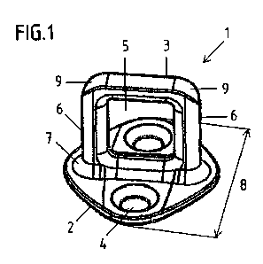
Fig. 1 shows a perspective view of the lock striker
Fig. 2 shows a side and top view (a) as well as a further side view (b) of a
lock striker.
Fig. 3 shows a schematic representation of starter blanks (a, b).
The lock striker 1 shown in Fig.1 to Fig. 2 shows a typical application for
the suggested
solution. Below, the suggested solution is explained with reference to a lock
striker for a
motor vehicle lock. The invention is, however, not limited to this.
6
CA 02886806 2015-03-31
The lock striker shown in Fig. 1 contains a base plate 2 and a lock bracket 3.
The lock
bracket 3 has an opening 5 at its centre, allowing engagement with a rotary
latch of a
lock when installed. Using respective tools, the opening 5 can already be
produced
during forming of the starter blank 11 or can be produced during a subsequent
work
step, such as by stamping or machining. The lock bracket 3 contains two legs
at both
sides of the opening 5, which are in contact with the base plate 2. In this
case, the base
plate 2 contains two holes 4 in form of drilled holes, having a cone shape and
allowing
fixing to, in particular, a body of a vehicle. The area between the base plate
2 and lock
bracket 3, i.e. the base plate / lock bracket transition 7, is preferably
reinforced in order
to provide a sturdier design. In the upper section of the lock bracket 3 and
at the
transitions to the respective legs 6, lock bracket / leg transitions 9
preferably have
transition radii, in order to suitably optimize the production of the lock
striker 1 for
reducing stressing of the tool. The rounded bracket / leg transitions 9 are
particularly
advantageously produced during cold forming. Depending on the shape of the
starter
blank 11, the diameter of the base plate 2 is in particular not larger than 50
mm or
alternatively 60 mm to 80 mm.
As apparent from Fig. 2 a), the holes 4 are arranged, in particular, at the
edges and on
opposite sides of the base plate 2. In this case the holes are positioned at a
distance of
30 mm to each other. The thickness 13 of the base plate 2 is preferably at
least 3 mm,
preferably 5 mm and even more preferably 4 mm. For a design with a stable
connection
with the lock bracket 3, the base plate / lock bracket transition 7 is
reinforced so that the
thickness of the base plate 2 is higher in this area. The thickness 14 of the
lock bracket
3 is preferably greater than the thickness 13 of the base plate 2 and is
preferably twice
as thick in order to ensure an adequate force absorption by the lock bracket
3.
Fig. 2 b) shows how the thickness 13 of the base plate 2 increases in the base
plate /
lock bracket transition 7. The height 10 of the lock bracket 3 is preferably
smaller than
the diameter 8 of the base plate. In particular, the height 10 of the lock
brackets does
not exceed 50 mm and is, for instance 34 mm.
Of particular significance is in this case the production method of the lock
striker 1
shown in Fig. 1 to Fig. 2. According to this production method the starter
blank 11 is
7
CA 02886806 2015-03-31
essentially block-shaped or cylindrical and in such a way that the cold
forming is a strain
hardening.
The starter blank 11 is preferably a wire or profile wire that is cold upset
or cold
pressed. Preferably, the starter blank has a square, rectangular or round
profile, with
this list not being exhaustive but containing any forms relevant for the
production
process, such as oval profiles. As a result of the suitably dimensioned
starter blank 11 a
specific cold forming is carried out that is associated with an increase in
the strength of
the lock striker 1, without unwanted high tool stressing.
Based on this, Fig. 3 d) shows an essentially block-shaped starter blank. The
width 12
of the starter blank 11 is preferably 15 mm to 35 mm. The length 131s
preferably 30 mm
to 45 mm. The height 14 is preferably 25 mm to 45 mm. The cross-sectional area
or the
profile surface of the starter blank 11 is derived from the width 12 and
length 13 of the
starter blank 11. The lock striker 1 formed therefrom, preferably contains a
base plate 2
with a diameter of no more than 50 mm.
Fig. 3 b) shows an essentially cylindrical starter blank 11. The diameter 15
of the starter
blank 11 is preferably 15 mm to 35 mm. The cross-sectional area or the profile
surface
of the starter blank 11 is determined by the diameter 15. The height 14 is
preferably 30
mm to 60 mm. The formed lock striker 1 does in this case preferably have a
diameter of
60 mm to 80 mm, such as 70 mm.
It has shown that lock strikers 1 produced in this way withstand the
respective tensile
forces. The lock strikers thus withstand a tensile load of 22 kN without the
lock strikers
having undergone additional heat treatment. After forming, the mechanical
strength is
furthermore at approx. 740 MPO to 835 MPa.
Particularly good results have also been achieved by heat treatment of the
lock striker,
for instance by tempering. The thus tempered lock strikers 1 withstand a
tensile load of
at least 30 kN. The mechanical strength is then approx. 920 MPa to 990 MPa. By
undergoing suitable heat treatment, in particular tempering, the produced lock
strikers 1
can meet particularly high requirements.
8
CA 02886806 2015-03-31
Reference numbers:
1 Lock striker
2 Base plate
3 Lock bracket
4 Hole
Opening
6 Leg
7 Base plate / lock bracket transition
8 Diameter of 2
9 Lock bracket / leg transition
Height of 3
11 Starter blank
12 Width of 11
13 Length of 11
14 Height of 11
Diameter of 11
16 Thickness of 2
17 Thickness of 3
9