Note: Descriptions are shown in the official language in which they were submitted.
CA 02887541 2015-04-10
WO 2014/064254 PCT/EP2013/072401
1
WIRELINE PUMP
Field of the invention
The present invention relates to a wireline pumping assembly for being
introduced in a wellbore or a casing and submerged in well fluid. Furthermore,
the invention relates to a use of the wireline pumping assembly, a method of
initiating a well using a wireline pumping assembly and a method of optimising
an initiation operation.
Background art
During oil and gas production, it is sometimes necessary to assist the
production
in a well due to a high hydro-static pressure. In situations where the well
itself is
not capable of generating the sufficient pressure to drive hydrocarbons to the
surface, or where the well has been deliberately or unintentionally "killed",
e.g.
by the presence of water in the well, a tool may be used to lift the well
fluid to
the upper part of the well. Such tools are often referred to as artificial
lift tools.
Artificial lift tools may be deployed in a well for longer or shorter periods
of time
depending on the specific conditions of the well. Sucker rod pumps are widely
used to draw oil from underground formations. However, such pumps entail a
large construction above ground as well as sucker rods extending all the way
down through the well to a sub-surface rod pump provided in the well. These
types of pumps may be suitable for use in wells requiring continuous pumping
over longer periods of time. However, for operations requiring pumping action
for
only a limited period of time, the sucker rod pump concept is inexpedient due
to
the associated considerable investments. Further, in sea-based oil fields
often
situated at great depths, the concept of a sucker rod extending from a force
generating installation at the surface to a pumping device downhole is ill-
suited.
Because water has a higher density than hydrocarbons, the presence of water in
a well may increase the hydro-static pressure, thereby preventing the pressure
in
the well from driving hydrocarbons to the surface. In situations where inflow
of
water has deliberately or unintentionally killed a well, downhole pumping
action
may be required to initiate or restart the well by removing water. Known
systems
CA 02887541 2015-04-10
WO 2014/064254 PCT/EP2013/072401
2
for removing water, such as coiled tubing gas lifting, require lots of surface
equipment, such as coil spool and gas tanks. Further, pumps used in known well
initiation systems often require high amounts of power which cannot be
supplied
via standard wireline cables. Special cables requiring additional surface
equipment are therefore required, which makes such operations more
complicated and expensive. A need therefore exists for a well initiation
system
which may be deployed using standard mono or multi-conductor wireline,
requiring a minimum of surface equipment, planning and logistics.
Summary of the invention
It is an object of the present invention to wholly or partly overcome the
above
disadvantages and drawbacks of the prior art. More specifically, it is an
object to
provide an improved well initiation system and an associated method for
initiating wells. Further, it is an object to provide a simple and reliable
wireline
pumping device which may be used for initiating wells which have been
intentionally or unintentionally killed.
The above objects, together with numerous other objects, advantages, and
features, which will become evident from the below description, are
accomplished
by a solution in accordance with the present invention by a wireline pumping
assembly for being introduced in a wellbore or a casing and submerged in well
fluid, the wireline pumping assembly extending in a longitudinal direction and
being adapted for connection with a wireline, and the wireline pumping
assembly
comprising a pump section comprising:
- a tubular pump housing providing a pump chamber,
- one or more inlets provided in a lower part of the tubular pump housing,
- a first valve for opening and closing the inlet,
- a plunger being slidingly disposed in the pump chamber, the plunger
comprising
a second valve controlling a flow of fluid from a first compartment of the
pump
chamber on one side of the plunger to a second compartment of the pump
chamber on the other side of the plunger,
- a pump rod operably connected to the plunger and extending from the
plunger
through the tubular pump housing, and
- one or more outlets provided in an upper part of the tubular pump housing,
wherein the wireline pumping assembly further comprises:
CA 02887541 2015-04-10
WO 2014/064254 PCT/EP2013/072401
3
- a linear actuator arranged in association with the tubular pump housing
for
driving the pump rod, whereby, when the wireline pumping assembly is at least
partially submerged into the well fluid, well fluid is drawn into the tubular
pump
housing through the one or more inlets, forced through the second valve of the
plunger, and expelled through the one or more outlets in the upper part of the
tubular pump housing.
Hereby, a simple and reliable pumping device is provided which is capable of
running using standard wireline and capable of pumping well fluids downhole.
Further, as the pumping device is deployable using standard wireline, the
amount
of equipment needed to deploy the device is substantially reduced compared to
known techniques for performing pumping operations downhole.
In an embodiment, the first valve may be a standing valve fixed in relation to
the
tubular pump housing and the second valve may be a travelling valve movable
with the plunger in relation to the tubular pump housing.
In another embodiment, the linear actuator may comprise:
- a tubular stroker cylinder providing one or more piston housings,
- one or more piston elements slidingly disposed in the piston housing to
divide
the piston housing into a first chamber and a second chamber,
- a stroker shaft operably connected to the piston element for connection
with
the pump rod to provide reciprocation of the plunger,
- a pump for alternately supplying hydraulic fluid under pressure to the
first
chamber and the second chamber of the tubular stroker cylinder to reciprocate
the piston element in the tubular stroker cylinder, and
- an electrical motor for driving the pump.
Furthermore, the linear actuator may comprise a plurality of piston elements
slidingly disposed in a plurality of piston housings and operably connected to
the
stroker shaft.
Moreover, the linear actuator may comprise an electric linear motor and a
stroker
shaft driven by the electric linear motor for connection with the pump rod to
provide reciprocation of the plunger.
CA 02887541 2015-04-10
WO 2014/064254 PCT/EP2013/072401
4
In an embodiment, the wireline pumping assembly may be adapted to pump at a
flow rate of approximately 5-15 litres per minute, preferably.
In another embodiment, the wireline pumping assembly may further comprise a
plug device for providing a seal in an annulus between the wireline pumping
assembly and the casing, the plug device comprising a base part connected with
the tubular pump housing and having a through-going bore, and one or more
sealing elements disposed around the base part, extendable from the base part
for sealing off the annulus.
Also, the base part may be the tubular pump housing.
Furthermore, the base part may be part of the tubular stroker cylinder and the
outlet(s) of the pump section may be arranged in the linear actuator.
Hereby, a simple and reliable pumping device is provided which is capable of
running using standard wireline and capable of initiating a well by pumping
well
fluids from one side of the plug device to the other side, whereby water may
be
removed. Further, as the pumping device is deployable using standard wireline,
the amount of equipment needed to deploy the device is substantially reduced
compared to known techniques for initiating wells. The reduced need for
equipment greatly reduces the complexity of the initiation operation, thereby
reducing the time and cost of such operations.
In yet another embodiment, the plug device may further comprise an anchor
mechanism for fixating the wireline pumping assembly in the well, the anchor
mechanism being slidingly disposed around the base part and comprising a
plurality of setting slips extendable from the base part in a substantially
radial
direction for engagement with the tubing or casing.
Furthermore, the plug device may further comprise a compression sleeve
slidingly disposed around the base part for compressing the one or more
sealing
elements, and the sealing elements may be adapted to extend from the base part
to seal off the annulus when the compression sleeve is displaced in the
longitudinal direction towards the one or more sealing elements, thereby
applying
a compression force to the one or more sealing elements.
CA 02887541 2015-04-10
WO 2014/064254 PCT/EP2013/072401
Moreover, the compression sleeve may comprise a cone-shaped section facing
towards the anchor mechanism, the cone-shaped section being adapted to force
the setting slips in a radial direction, at least upon activation of the
anchor
mechanism, when the plurality of setting slips are displaced towards the
5 compression sleeve thereby engaging the cone-shaped section.
In addition, the compression sleeve may be adapted to be displaced by
displacement of the anchor mechanism, resulting in a subsequent compression of
the sealing elements by the compression sleeve.
In an embodiment, the wireline pumping assembly may further comprise an
equalisation valve for equalising a differential pressure across the plug, at
least
prior to disengaging of the plug, when the plug device is set in a well.
Furthermore, the plug device may comprise the equalisation valve.
Moreover, the wireline pumping assembly may further comprise one or more
sensors for measuring a differential pressure across the plug device when the
plug device is set in a well.
Additionally, the wireline pumping assembly may further comprise an anchor
section for anchoring the wireline pumping assembly in the well, the anchor
section comprising a plurality of hydraulically activatable anchoring elements
extendable from the tool body, for engagement with the casing.
Also, the wireline pumping assembly may further comprise a driving unit for
driving the wireline pumping assembly forward in deviated wells.
In one embodiment, the wireline pumping system may comprising a wireline
pumping assembly as described above, and a plug device for providing a seal in
an annulus between the plug device and the casing, the plug device comprising
a
base part having a through-going bore adapted to be connected with the tubular
pump housing of the pump section, and one or more sealing elements disposed
around the base part, extendable from the base part for sealing off the
annulus,
wherein the wireline pumping assembly is adapted for connection with the plug
device downhole following setting of the plug device in the well.
CA 02887541 2015-04-10
WO 2014/064254 PCT/EP2013/072401
6
The present invention furthermore relates to a use of the wireline pumping
assembly as described above or the wireline pumping system described above for
initiation of a killed well by removing water or mud present in the well using
the
pumping action provided by the pumping assembly.
Moreover, the present invention relates to a method of initiating a well using
a
wireline pumping assembly as described above, comprising the steps of:
- inserting the wireline pumping assembly into the wellbore,
- setting the plug device for providing a seal in an annulus between the
plug
device and the casing, the plug devise comprising:
- a base part having a through-going bore adapted to be connected with
the tubular pump housing of the pump section, and
- one or more sealing elements disposed around the base part,
extendable from the base part for sealing off the annulus,
- operating the pump section of the wireline pumping assembly to pump fluid
past the plug device until a pressure below the plug device is sufficient to
make
the well run by itself,
- equalising the pressure over the plug by operating the equalisation
valve, and
- removing the wireline pumping assembly from the well.
The method may further comprise the step of removing the plug device from the
well.
Finally, the present invention relates to a method of optimising an initiation
operation, comprising the steps of:
- determining a pressure level in the well below the plug device,
sufficient to
make the well run by itself,
- continuously monitoring the pressure in the well below the plug device
while the
pump section is operated to pump fluid from below the plug device to above the
plug device, and
- determining when the predetermined pressure level is reached, following
which
the operation of the pump section may be stopped.
CA 02887541 2015-04-10
WO 2014/064254 PCT/EP2013/072401
7
Brief description of the drawings
The invention and its many advantages will be described in more detail below
with reference to the accompanying schematic drawings, which for the purpose
of
illustration show some non-limiting embodiments and in which
Fig. 1 shows a wireline pumping assembly,
Fig. 2 shows a cross-section of one embodiment of a pump section of the
wireline
pumping assembly,
Fig. 3a shows a cross-section of one embodiment of a plug device of the
wireline
pumping assembly,
Fig. 3b shows a cross-section of another embodiment of a plug device,
Fig. 4a shows a cross-section of one embodiment of a linear actuator,
Fig. 4b shows a cross-section of another embodiment of a linear actuator,
Fig. 5a shows the wireline pumping assembly of Fig. 1 in a set condition
inside a
casing downhole,
Fig. 5b shows a close-up of a lower section of the wireline pumping assembly
shown in Fig. 5a,
Fig. 6 shows another embodiment of the wireline pumping assembly comprising a
driving unit and an anchor section,
Fig. 7 shows another embodiment of the wireline pumping assembly, and
Fig. 8 shows yet another embodiment of the wireline pumping assembly.
All the figures are highly schematic and not necessarily to scale, and they
show
only those parts which are necessary in order to elucidate the invention,
other
parts being omitted or merely suggested.
CA 02887541 2015-04-10
WO 2014/064254 PCT/EP2013/072401
8
Detailed description of the invention
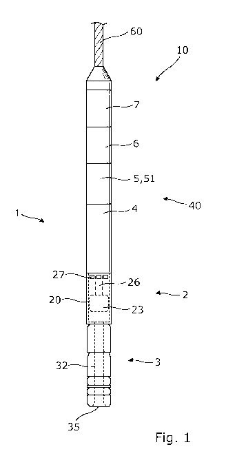
Fig. 1 shows a wireline pumping assembly 1 comprising a pump section 2, a plug
device 3, a linear actuator 40 and an electronic section 7. The wireline
pumping
assembly is a downhole assembly adapted to be suspended in a well using a
wireline 60 operably connected at a top end of the wireline pumping assembly.
At
the bottom end of the wireline pumping assembly, the plug device is arranged
in
continuation of the pump section. The plug device may be an integrated part of
the wireline pumping assembly or adapted to be releasably connected with the
wireline pumping assembly downhole.
The pump section 2 is operably connected to the linear actuator 40, and the
linear actuator provides the power input required to drive the pump section 2.
The wireline pumping assembly is powered through the wireline 60, and the
electronic section controls the powering and operation of the remainder of the
wireline pumping assembly.
Fig. 2 shows a pump section 2 of the wireline pumping assembly, comprising a
tubular pump housing 20 also constituting a tool housing. The pump housing 20
defines a pump chamber 201. A lower part of the pump housing is provided with
inlets 21 in fluid communication with the pump chamber 201, and an upper part
of the pump housing is provided with a plurality of outlets 27 in fluid
communication with the pump chamber. Further, in a lower part of the tubular
pump housing, a first valve 22, such as a standing valve is arranged for
controlling the flow of fluid through the inlet 21. In the pump chamber 201, a
plunger 23 is slidingly disposed, thereby dividing the pump chamber into a
first
compartment 202 and a second compartment 203. To control the flow of fluid
from the first compartment 202, past the plunger 23 to the second compartment
203, the plunger is provided with a second valve 24, such as a travelling
valve.
The pump section 2 further comprises a pump rod 26 operably connected to the
plunger and extending from the plunger through the tubular pump housing for
connection with a stroker shaft 45 (shown in Fig. 4a) of the linear actuator.
The wireline pumping assembly further comprises a linear actuator 40 arranged
in association with the tubular pump housing 20, as shown in Fig. 1. As shown
in
Fig. 4a, the linear actuator 40 comprises a tubular stroker cylinder 4
defining a
piston housing 47 and a piston element 46 slidingly disposed in the piston
CA 02887541 2015-04-10
WO 2014/064254 PCT/EP2013/072401
9
housing to divide the piston housing into a first chamber 41 and a second
chamber 42. A stroker shaft 45 extending from the piston element is operably
connected with the pump rod of the pump section, as described above, to
provide
reciprocation of the plunger in the pump chamber. The linear actuator further
comprises a pump 5 (not shown in Fig. 4a) for alternately supplying hydraulic
fluid under pressure to the first chamber 41 and the second chamber 42 of the
tubular stroker cylinder, and an electrical motor 6 (shown in Fig. 1) is
provided
for driving the pump. When fluid is alternately supplied to the first chamber
41
and a second chamber 42, the piston element is reciprocated in the tubular
stroker cylinder, thereby creating a linear motion. The linear motion is
transferred via the stroker shaft 45 to the pump rod 26 (shown in Fig. 1),
thereby reciprocating the plunger in the pump chamber. When the plunger is
reciprocated, a pumping effect is created in the pump section and, provided
that
the wireline pumping assembly is at least partially submerged into a well
fluid,
well fluid is drawn into the pump chamber through the one or more inlets in
the
lower part of the tubular pump housing, forced through the second valve of the
plunger, and expelled through the plurality of outlets in the upper part of
the
tubular pump housing. In another embodiment (not shown), the pump housing
may be provided as a separate pump housing inside a tubular tool housing.
More specifically, during an upstroke motion, the plunger moves away from the
inlet 21 and the first valve 22, resulting in well fluid being sucked in
through the
inlet 21, past the open first valve 22 and into the first compartment 202 of
the
pump chamber. The first valve is a check-valve only allowing fluid to flow
into the
pump chamber. Thus, as the plunger 23 reaches an upper extreme position, the
first compartment of the pump chamber has been flooded. A subsequent down-
stroke motion of the plunger, wherein the plunger moves towards the inlet 21
and the first valve 22, forces the fluid through the travelling valve 24 of
the
plunger and into the second compartment 203 of the pump chamber. During the
next upstroke motion, the fluid in the second compartment 203 is expelled out
through the plurality of outlets in the tubular pump housing as the second
valve
prevents fluid from flowing in the direction towards the first compartment
202. In
the shown embodiment, the first valve and the second valve are embodied as
check-valves of the ball-type and comprise a displaceable valve ball 221, 241
cooperating with a valve seat 222, 243 to control the flow direction. However,
the
skilled person would know that many other types of valves may be envisaged
providing similar functionality. Further, the design of the pump section is
based
CA 02887541 2015-04-10
WO 2014/064254 PCT/EP2013/072401
on the principles of widely used rod pumps, and other designs of the pump
section may thus be envisaged by the skilled person without departing from the
invention.
5 Details about the design of the linear actuator are shown in Figs. 4a and
4b
showing different embodiments of a linear actuator. In both embodiments, the
stroker shaft 45 extends through the tubular stroker cylinder 4 sectioned into
one
or more piston housings 47 by partitions 48. The partitions comprise a sealing
means 49b, such as an 0-ring, in order to provide a sealing connection between
10 the partitions and the stroker shaft 45. In each of the piston housings
47, a
piston element 46 is provided around the stroker shaft 45 so that the stroker
shaft 45 may run back and forth within the tubular stroker cylinder 4 to
provide
the linear motion. Each of the piston elements 46 divides each of the one or
more
piston housings into a first chamber 41 and a second chamber 42, and the
piston
elements are provided with sealing means 49a in order to provide a sealing
connection between the inside of the piston housing 47 and the outside of the
piston element 46. As shown in Fig. 4a, fluid is alternately supplied to the
first
chamber 41 and the second chamber 42 via the respective fluid channels 43, 44.
In the embodiment shown in Fig. 4b, only the fluid channels in fluid
communication with the fist piston housing are shown, however, the other
piston
housings are provided with a similar arrangement of fluid channels. To provide
the linear motion of the linear actuator, the pump pumps fluid into the first
chamber by sucking a corresponding amount of fluid from the second chamber
42, and vice versa. When the first chamber 41 is substantially filled, the
pump
shifts its pumping direction and pumps fluid from the first chamber 41 into
the
second chamber 42. Consequently, the piston element 46 is forced in the
opposite direction. Consequently, the stroker shaft 45 is forced back and
forth,
thereby providing the linear motion. As can be seen in Fig. 4a, the first
chamber
41 is provided with a fluid channel 43 at one end of the piston housing 47,
and
the second chamber 42 is provided with a fluid channel 44 at the opposite end
of
the piston housing 47. In this way, fluid can be sucked or pumped into each
chamber until the piston element 46 almost abuts the partitions 48. The linear
actuator is thus a closed system, meaning that the same fluid is recirculated
by
being pumped back and forth in the piston housing 47 in order to move the one
or more piston elements 46 back and forth.
CA 02887541 2015-04-10
WO 2014/064254 PCT/EP2013/072401
11
In another embodiment, the linear actuator may comprise an electric linear
motor 51 driving the stroker shaft 45.
Fig. 3a shows a plug device 3 adapted to be arranged in continuation of the
pump
section, as shown in Fig. 1, so that an assembly inlet 35 arranged at the end
of
the plug device is in fluid communication with the inlet of the pump section 2
through outlet 36. The plug device is adapted for anchoring the wireline
pumping
assembly in the well and for providing a circumferential seal in an annulus 62
between the wireline pumping assembly and the casing 61 (shown in Fig. 5a) or
an inside wall of the well. The plug device comprises a base part 31 having a
through-going bore 32 extending in a longitudinal direction and a plurality of
sealing elements 34 disposed around the base part for sealing off the annulus.
Above the sealing elements 34, a compression sleeve 38 and an anchor
mechanism 33 are slidingly disposed around the base part. The anchor
mechanism comprises a plurality of setting slips 331 which are adapted to
extend
from the base part in a substantially radial direction. When the plug device
is
coupled to the pump section, the bore 32 of the plug device is in fluid
communication with the inlet of the pump section. Well fluid may thus be
sucked
into the pump chamber via the bore 32.
To set or activate the plug device, a force is applied to the anchor mechanism
33
in the longitudinal direction, thereby displacing the anchor mechanism towards
the sealing elements. As the anchor mechanism is displaced, the setting slips
331
engage a cone-shaped section 381 of the compression sleeve facing towards the
anchor mechanism. The cone-shape of the compression sleeve forces the setting
slips in an outwards radial direction for engagement with the casing when the
wireline pumping assembly is positioned downhole. As the compression sleeve is
also slidingly disposed around the base part 31, displacement of the anchor
mechanism 33 displaces the compression sleeve in the same direction towards
the sealing elements. The sealing elements 34 are adapted to extend from the
base part 31 to seal off the annulus when the compression sleeve is displaced.
Displacement of the compression sleeve applies a compression force to the
sealing elements 34, whereby the sealing elements are compressed in the
longitudinal direction, resulting in the sealing elements buckling outwards.
The
cooperation relationship of the anchor mechanism, the compression sleeve 38
and the sealing elements 34 thus results in the setting slips 331 and the
sealing
CA 02887541 2015-04-10
WO 2014/064254 PCT/EP2013/072401
12
elements 34 being simultaneously extended from the base part 31 to set the
plug
device.
In one embodiment, the wireline pumping assembly may further comprise an
equalisation valve 37, as shown in Fig. 3b. The equalisation valve is adapted
to
control the flow through the bore 32 of the plug device 3. The equalisation
valve
may also be used for equalising a differential pressure created across the
plug
device when the plug device is set in the well and well fluid is pumped from
the
lower sealed-off section 66a of the well below the plug to the upper section
66b
of the well above the sealing elements, as shown in Figs. 5a and 5b. As shown
in
Fig. 3b, the equalisation valve is provided in the bore 32 of the plug.
However, if
the plug device is an integrated part of the wireline pumping assembly, the
equalisation valve may also be incorporated in the pump section (not shown).
To
monitor and measure the differential pressure across the plug device, the plug
device or other parts of the wireline pumping assembly may comprise a system
for measuring the differential pressure, such as one or more sensors 39 for
measuring the pressure in the lower and the upper sections of the well. The
differential pressure may, however, also be determined based on other
principles
known to the skilled person, inter alia based on the force required to drive
the
plunger in the pump section.
Further, when the differential is negative, i.e. when the pressure in the
lower
sealed-off section 66a of the well below the set sealing element is higher
than the
pressure in the upper section 66b of the well, the well may start flowing by
itself
as the well fluid flows from regions with higher pressure towards regions with
lower pressure. In the embodiment of the pump section shown in Fig. 2, the
design of the first valve 22 and the second valve 24 allows well fluid to flow
from
the inlet 21 towards the outlets 27 regardless of the position of the plunger
23.
Hereby, the wireline pumping assembly operates in a contributory way by
boosting the existing flow in the well.
Based on the flow through the plug device 3 and/or the flow through the pump
section 2, the differential pressure may also be measured by a single sensor
arranged across the plug device or by a single sensor in the plunger
conducting
measurements over time. An alternative method for determining the differential
pressure is to measure the flow through the outlets 27 of the pump section,
e.g.
by providing a flow meter 28 in one or more of the outlets 27.
CA 02887541 2015-04-10
WO 2014/064254 PCT/EP2013/072401
13
In Fig. 6, the wireline pumping assembly is provided with a driving unit 9 and
an
anchoring section 8. The driving section is adapted to drive the wireline
pumping
assembly forward in inclined sections of the well, and the anchoring section
may
be used for fixating the wireline pumping assembly downhole.
In Fig. 7, the wireline pumping assembly 1 comprises the plug device 3 having
the through bore 32 in which the stroker shaft 45 extends and the stroker
shaft
is connected with the pump rod 26 of the pump section 2. The pump section is,
in
the same way as explained above, operably connected to the linear actuator 40.
The outlets 27 are arranged in the linear actuator 40 above the plug device
and
closer to the plug device than the inlet 21 of the pump section 2. Thus, the
base
part of the plug device forms part of the linear actuator.
In Fig. 8, the plug device 3 is arranged so that the base part is the tubular
pump
housing and the sealing element 34 is disposed around the tubular pump housing
and is radially expandable from the tubular pump housing. The sealing element
is
an inflatable elastomeric material which is inflated by the linear actuator
before
the actuator drives the pump section. As can be seen, the outlets 27 are
arranged in the top of the tubular pump housing and the inlet in the bottom of
the housing.
The wireline pumping assembly may be used for various purposes requiring
pumping downhole. In particular, the wireline pumping assembly may be used for
initiation of a well that has been intentionally killed, e.g. to perform
maintenance
operations or the like downhole. To kill a well, water may be introduced into
the
well, thereby increasing the hydrostatic pressure preventing hydro carbon from
being forced to the surface by the pressure exerted by the sourrounding
formation. Such a well may be initiated by subsequently removing the water
from
the the well. To do so, a wireline pumping assembly according to the present
invention is introduced into a well through the lubricater (not shown) at the
surface of the well.
Figs. 5a and 5b show the wireline pumping assembly being submerged in a well
65 via a wireline 60. When the wireline pumping assembly 1 has reached the
specified position, the plug device is activated, whereby the setting slips
331
engage the casing 61 to fixate the wireline pumping assembly, and the sealing
elements 34 are simultaneously extended to provide a circumferential seal
CA 02887541 2015-04-10
WO 2014/064254 PCT/EP2013/072401
14
sealing off the annulus. When the wireline pumping assembly has been set, the
well is thus divided into a lower sealed-off section 66a of the well below the
set
sealing elements and an upper section 66b of the well above the set sealing
elements.
Next, the pump section 2 is activated to pump well fluid from below the set
sealing elements 34 to the upper section 66b of the well. Pumping well fluid
from
the lower sealed-off section 66a to the upper section of the well results in
lifting
of the well fluid in the upper section towards the surface and in a pressure
build-
up in the lower section of the well. The pressure in the upper and/or the
lower
section is continuously monitored to be able to determine when enough water
has been removed for the well to be able to run by itself. When the desired
pressure in the lower sealed-off section 66a has been reached, the operation
of
the pump section may be stopped.
Before the wireline pumping assembly can be removed, the pressure across the
plug device has to be equalised, which may be done by operating the
equalisation
valve provided in the plug device or in another part of the wireline pumping
assembly. When the pressure has been equalised, the wireline pumping assembly
is pulled up into the lubricator and subsequently removed from the well.
Subsequently, the wireline pumping assembly may easily be moved to the next
well to perform a similar initiation operation.
In another embodiment, the plug device 3 and the remainder of the wireline
pumping assembly 1 may be separately operated and adapted to be releasably
connected downhole. In that case, first the plug device is inserted into the
well
and set in the desired position by activating the anchoring mechanism and the
sealing elements. Subsequently, the wireline pumping assembly is introduced
into the well and connected with the plug device. When the desired pressure in
the lower sealed-off section 66a has been reached by operating the pump
section, the wireline pumping assembly may be removed from the well.
Subsequently, the pressure may be equalised using the equalisation valve
provided in the plug device, and the plug device may be removed.
Additionally, the design of the plug device 3 and the remainder of the
wireline
pumping assembly 1 as separate and releasably connectable units may allow for
CA 02887541 2015-04-10
WO 2014/064254 PCT/EP2013/072401
the plug device 3 to be arranged in the well downhole permanently or for
longer
periods of time.
Further, as described above, the design of the pump section allows well fluid
to
5 flow from the inlet 21 towards the outlets 27 regardless of the position
of the
plunger 23. The wireline pumping assembly may thus be arranged in the well
downhole permanently or for longer periods of time, operating based on the
actual demand for boosting the flow in the well. If, for some reason, the flow
in
the well suddenly drops, the wireline pumping assembly may be activated to
10 boost the flow until the well is once again able to run by itself. The
wireline
pumping assembly may be activated either automatically based on a measured
pressure in the well or by a signal received from an operator. The measured
differential pressure across the set sealing elements may thus be used to
control
the operation of the pumping action of the wireline pumping assembly by
15 continuously activating and deactivating the pumping action to boost the
flow in
the well.
By fluid or well fluid is meant any kind of fluid that may be present in oil
or gas
wells downhole, such as natural gas, oil, oil mud, crude oil, water, etc. By
gas is
meant any kind of gas composition present in a well, completion, or open hole,
and by oil is meant any kind of oil composition, such as crude oil, an oil-
containing fluid, etc. Gas, oil, and water fluids may thus all comprise other
elements or substances than gas, oil, and/or water, respectively.
By a casing is meant any kind of pipe, tubing, tubular, liner, string etc.
used
downhole in relation to oil or natural gas production.
In the event that the assembly is not submergible all the way into the casing,
a
downhole tractor can be used to push the assembly all the way into position in
the well. The downhole tractor may have projectable arms having wheels,
wherein the wheels contact the inner surface of the casing for propelling the
tractor and the assembly forward in the casing. A downhole tractor is any kind
of
driving tool capable of pushing or pulling tools in a well downhole, such as a
Well
Tractor .
Also, the linear actuator may be a Well Stroker . Although the invention has
been described in the above in connection with preferred embodiments of the
CA 02887541 2015-04-10
WO 2014/064254 PCT/EP2013/072401
16
invention, it will be evident for a person skilled in the art that several
modifications are conceivable without departing from the invention as defined
by
the following claims.