Note: Descriptions are shown in the official language in which they were submitted.
CA 02887754 2015-04-10
DOOR AND WINDOW FRAME MOLDING SYSTEM
FIELD OF THE INVENTION
The invention generally relates to decorative and/or protective molding such
as
trim and baseboards and, more particularly, to systems and methods for
mounting
molding to door and window frames, adjacent the bases of walls, and the like.
BACKGROUND OF THE INVENTION
Buildings (e.g., constructed houses, office buildings, etc.) often include a
number
of standard components such as a foundation, horizontal girders and joists,
subflooring
interconnected to the joists, vertical studs extending from the girder and
joists, drywall
(e.g., gypsumboard, sheetrock, plasterboard) secured to the vertical studs,
and the like.
Part of the process of constructing a building includes creating door and
window "rough
openings." For instance, a door or window rough opening is typically formed by
a pair of
spaced vertical stud assemblies (e.g., each including a "jack stud" and a
"king stud")
interconnected by a (e.g., horizontal) header and possibly by a sill. A frame
(e.g., casing)
including a plurality of frame members (e.g., spaced jambs or posts,
cross/transverse-
members interconnecting spaced jambs, etc.) is then inserted into the rough
opening and
appropriately secured to the studs, header, and/or sill.
In the case of a door frame, for instance, a "hinge jamb" to which a door is
hingedly secured may be secured to one of the stud assemblies and a "stop
jamb" against
which the door abuts to prevent the door from swinging all the way through the
door
frame may be secured to the other of the stud assemblies. In one arrangement,
door
frames may include cross-members that interconnect the upper portions of the
hinge and
door jambs (e.g., such as in the case of pre-hung doors). In the case of a
window frame,
for instance, a pair of tracks may be respectively attached to the pair of
spaced jambs
within which a window may slide or travel in first and second opposite
directions.
In any event, molding (e.g., baseboards, trim, etc.) is often installed at
various
locations of a building for purposes of concealing interfaces between
structural
components, providing for a more aesthetically pleasing appearance, and the
like. For
1
CA 02887754 2015-04-10
instance, baseboards are often mounted over the drywall (e.g., gypsumboard,
sheetrock,
plasterboard) adjacent the base of interior walls via inserting (e.g.,
hammering, forcing)
fasteners (e.g., nails, staples) through the baseboards (via an outer surface
of the
baseboards) and into the vertical studs to conceal the interface between the
drywall and
the floor. As another example, trim is often interconnected or mounted to the
jambs
and/or frames of doors and windows by inserting fasteners through the trim
(via an outer
surface of the trim) and into the jambs and/or frames to conceal the
interfaces between
the door/window frames and the jambs.
SUMMARY OF THE INVENTION
Inserting fasteners (e.g., nails, staples, etc.) through molding and into
structural
building members (e.g., jambs, frames, studs, etc.) often creates holes (e.g.,
notches,
openings, depressions, cracks, etc.) in the molding (e.g., from the fastener
itself, from a
hammer or staple gun used to insert the fastener, etc.) that are typically
patched (e.g., via
joint compound or putty) and/or painted over to conceal the holes. However, it
is often
difficult to completely conceal such holes which reduces the likelihood of a
highly
smooth finish on the outside of the molding. Furthermore, driving fasteners
though the
outside surface of the molding and into the building components can be a
cumbersome as
it typically requires a nail or staple gun or having to hold nails with one
hand and
hammer numerous nails with the other hand one at a time. Still further,
removal of
molding attached in the aforementioned manner (e.g., when painting an adjacent
wall, for
replacing the molding, etc.) often damages the molding thus limiting its reuse
and leading
to an increase in waste.
In this regard, disclosed herein are apparatuses, systems, methods, kits, etc.
("utilities") for use in mounting molding members (e.g., trim, baseboards,
etc.),
decorative pieces, and/or the like onto and over building components (e.g.,
drywall, studs,
etc.) and/or interfaces between building components in a manner that
eliminates or at
least reduces the need for driving fasteners through the outside surface of
the molding
members and thus eliminates many of the problems and inefficiencies associated
with
existing manners of mounting molding members, decorative pieces, and/or the
like onto
2
CA 02887754 2015-04-10
building components. As will be discussed in more detail herein, at least some
of the
disclosed utilities include use of a connection member that is configured
(e.g., sized,
shaped, etc.) to be disposed or received in a groove of a framing member
(e.g., door or
window jamb, interconnect member, etc.) or a molding member (or a decorative
piece).
In one arrangement, the connection member may broadly include a base member
(e.g., in
one embodiment, a generally planar member, such as one or more strips or
layers of
material) along with a fastening apparatus disposed on at least one side of
the base
member so as to face or be directed away from the base member towards and/or
past an
entrance to the groove. The other of the framing member and molding member may
include a projecting member that is configured to be received in the groove
and engage
with the fastening apparatus of the connection member.
As just one non-limiting example, assume some or all of a door or window frame
(e.g., including a pair of spaced jambs and a top member interconnecting the
jambs)
includes a groove (e.g., track, etc.) running therealong. Further assume that
one or more
connection members, each in the form of a base member having a series of
spaced
fasteners (e.g., nails, staples, etc.) extending away from opposite sides
thereof, are placed
or disposed in the groove (e.g., so that the fasteners of one of the sides at
least partially
engage a (e.g., bottom, back, etc.) surface of the groove). After a projecting
member of a
molding member (e.g., where the projecting member has a width and height
corresponding to the width and depth of the groove) is aligned with the
groove, the
projecting member may be inserted (e.g., urged, forced) into the groove so as
to engage
with the fasteners of the connection member and mount the molding member to
the
framing member.
For instance, any appropriate tool (e.g., rubber mallet or the like) may be
used to
apply a force to the outside of the molding member (e.g., a side opposite of
the side on
which the projecting member is disposed) so as to drive the projecting member
into the
groove. As the projecting member is being driven into the groove, the
fasteners on one
side of the base member may pierce and be driven into the projecting member
while the
fasteners on the opposite side of the base member may pierce and be driven
into the
surface of the groove. Continued driving of the projecting member into the
groove may
3
CA 02887754 2015-04-10
eventually substantially sandwich (e.g., compress) the base member between the
projecting member and the bottom surface of the groove. The fasteners may be
of a
length so as to not protrude through the front surface of the molding members
when
seated in the groove. At this point, the molding member may be mounted to the
framing
member, a covering portion of the molding member may cover an interface (e.g.,
abutment or substantial abutment) between the framing member and a building
component (e.g., drywall, stud, etc.), and the connection member may be
concealed (e.g.,
hidden) from view within the groove and/or between the molding member and the
framing member.
As an example, respective molding members may be similarly mounted about the
various framing members of the frame. While the opposite sides of the base
member of
the connection member have each been described as including a series of
protruding
fasteners, one or both sides may additionally or alternatively include other
fastening
apparatuses such as adhesives (e.g., which may be covered by a releasable
strip of
material before use) and/or the like. Furthermore, the disclosed utilities
also include a
vice versa arrangement whereby the groove is disposed in a surface of the
molding
member and the projecting member is disposed on the framing member.
In one arrangement, one or both of the framing member and molding member
may include an extension member that is configured to space the covering
member of the
molding member away from a building component. This arrangement may be useful
when drywall is to be mounted over a stud onto which the framing member is
secured
and/or over other paneling. For instance, the extension member may include
opposite
sides, where one of the sides includes a projecting member that is configured
to be
received into the groove of one of the framing member and the molding member,
and
where the other of the sides includes a groove that is configured to receive
the projecting
member of the other of the framing member and the molding member. In this
arrangement, respective connection members may be disposed in the groove of
the
extension member and the groove of the framing or molding member as discussed
previously.
4
CA 02887754 2015-04-10
In contrast to existing arrangements, the disclosed utilities allow molding
members to be mounted and secured over building component interfaces (e.g.,
between
framing members and studs, between framing members and drywall, etc.) free of
having
to drive fasteners through the molding members into the building components
via an
outside surface of the molding members. More specifically, placement of a
connection
member within a groove of a framing member over which a molding member is
disposed
(or within a groove of the molding member that faces the framing member)
effectively
interconnects the molding member to the framing member while concealing the
connection member (e.g., and/or fasteners) and eliminating (or at least
reducing) the need
to drive fasteners all the way through the molding member via an outside
surface of the
molding.
Furthermore, receiving (e.g., inserting, forcing) a projecting member (on the
other
of the molding member and framing member) into the groove so as to engage the
fastening apparatus (e.g., fasteners, adhesives, and/or the like) of the
connection member
advantageously serves to simultaneously laterally stabilize the molding member
(e.g., due
to abutment or substantial abutment between the outside surfaces of the
projecting
member and the inside surfaces of the groove) and secure the molding member
against
inadvertent removal from the framing member. Still further, the molding member
can be
efficiently and quickly removed from the framing member free or substantially
free of
damaging the molding member and/or building components, such as by sliding a
blade or
the like between the molding member and the building component and prying
(e.g.,
torquing) the molding member away from the building component and framing
member
(e.g., so as to remove the projecting member from the groove and thus out of
engagement
with the connection member).
In one aspect, a system for use with an opening in a building is disclosed,
where
the opening is defined by a plurality of structural members (e.g., studs,
headers, etc.).
The system includes a framing member (e.g., jamb) securable to one of the
plurality of
structural members, where the framing member includes one of a projecting
member and
a groove, and where the groove is defined by at least surface. The system also
includes a
molding member including the other of the projecting member and the groove,
where the
5
CA 02887754 2015-04-10
projecting member is receivable in the groove, and a connection member
receivable in
the groove when the projecting member is received in the groove to secure the
molding
member to the framing member.
For instance, the connection member may include a body including first and
second opposite surfaces, and a fastening apparatus (e.g., series of
protruding fasteners,
adhesives, etc.) disposed on at least one of the first and second surfaces of
the body,
where the fastening apparatus is interconnectable to one of the projecting
member and the
surface of the groove.
In another aspect, a kit for concealing an interface between adjacent
components
of a building includes an elongated molding member including a body having
first and
second sides, and a connection member configured to attach the molding member
to one
of the components over the interface between the adjacent components. The
first side of
the body is configured to face in a first direction towards the interface and
the second side
is configured to face in a second direction that is opposite to the first
direction. The first
side of the body includes a projecting member thereon that is receivable
within a groove
defined by a surface of one of the components of the building. The connection
member
includes a body including first and second opposite surfaces, where the first
surface is
configured to face in the first direction, where the second surface is
configured to face in
the second direction, and where the body is receivable in the groove between
the surface
of the component and the projecting member. The connection member also
includes a
fastening apparatus disposed on the first surface of the body, where the
fastening
apparatus is configured to engage with the surface of the component that
defines the
groove.
In a further aspect, a kit for concealing an interface between adjacent
components
of a building includes an elongated molding member including a body having a
groove
on a side thereof, where the groove is defined by at least one surface in the
side of the
body. The kit also includes a connection member including a body receivable in
the
groove and a fastening apparatus on a second of first and second opposite
surfaces of the
body. The first surface is configured to face in a first direction towards the
surface of the
groove and the second surface is configured to face in a second direction
opposite to the
6
CA 02887754 2015-04-10
first direction. The fastening apparatus is configured to secure the molding
member over
the interface between the adjacent components of the building.
In a still further aspect, a method of mounting a molding member over an
interface between a framing member and a component of a building is disclosed,
where
the molding member includes one of a groove and a projecting member, and where
the
framing member includes the other of a groove and a projecting member. The
method
includes disposing a connection member at least partially into the groove,
where the
connection member includes a body having first and second opposite surfaces,
where the
connection member includes a first fastening apparatus on the first surface of
the body,
and where the connection member includes a second fastening apparatus on the
second
surface of the body. The method also includes first engaging, during the
disposing, the
first fastening apparatus with a surface defining the groove; aligning the one
of the
groove and projecting member of the molding member with the other of the
groove and
projecting member of the framing member; receiving the projecting member in
the
groove; and second engaging, during the receiving, the projecting member with
the
second fastening apparatus to mount the molding member over the interface,
where the
body is disposed within the groove between the projecting member and the
surface of the
groove.
Various refinements may exist of the features noted in relation to the various
aspects. Further features may also be incorporated in the various aspects.
These
refinements and additional features may exist individually or in any
combination, and
various features of the aspects may be combined. In addition to the exemplary
aspects
and embodiments described above, further aspects and embodiments will become
apparent by reference to the drawings and by study of the following
descriptions.
DESCRIPTION OF THE DRAWINGS
For a more complete understanding of the present invention and further
advantages thereof, reference is now made to the following Detailed
Description, taken in
conjunction with the drawings, in which:
7
CA 02887754 2015-04-10
Figure 1 is a perspective view of a partially assembled door structure
according to
one embodiment.
Figure 2 is another perspective view of the door structure of Figure 1 with
the
door removed and illustrating structural building components used to form a
rough
opening for a door frame.
Figure 3a is an exploded perspective view of a system for mounting molding
onto
a frame of a door according to an embodiment.
Figure 3b is a perspective view similar to Figure 3a but where the molding is
mounted onto the frame of the door.
Figure 4 is a perspective view of the embodiment of Figure 3 but after a
connection member has been disposed into a groove of a framing member of the
frame.
Figure 5a is a perspective view of a tool for installing a connection member
into a
groove of a framing member or a molding member.
Figure 5b is another perspective view of the tool of Figure 5a and showing a
connection member being attached to the tool.
Figure 5c is a perspective view showing the tool of Figure 5a being used to
insert
the connection member into a groove of a framing member.
Figure 6 is a perspective view of the embodiment of Figure 4 and illustrating
a
molding member being installed into the groove of the framing member.
Figure 7a is an exploded perspective view of a system for mounting molding
onto
a frame of door according to an embodiment.
Figure 7b is a perspective view similar to Figure 7a but where the molding is
mounted onto the frame of the door.
Figure 8 is a top view of an embodiment similar to that in of Figure 7b.
Figure 9 is an exploded perspective view of a connection member according to
an
embodiment.
Figure 10 is a perspective view of a connection member according to an
embodiment.
Figure 11 is a side view of a connection member according to an embodiment.
8
CA 02887754 2015-04-10
Figure 12 is an exploded perspective view of a system for mounting molding
onto
a frame of a door according to an embodiment.
Figure 13 is a sectional view of a system for mounting molding onto a frame of
a
door according to an embodiment.
Figure 14 is an exploded perspective view of a molding member in the form of a
baseboard and including a groove into which a connection member may be
disposed
according to an embodiment.
Figure 15 illustrates the baseboard and connection member of Figure 9 being
mounted onto the base of a wall.
Figure 16 is a sectional view of a system for mounting molding onto a frame of
a
door according to an embodiment.
Figure 17a is a perspective view of a connection member according to an
embodiment.
Figure 17b is a plan view of the connection member of Figure 17a.
Figure 18a is a perspective view of a connection member according to an
embodiment.
Figure 18b is a plan view of the connection member of Figure 18a.
Figure 19 is a perspective view of the tool of Figures 5a-5c and a plurality
of
fasteners configured to be inserted into apertures of the tool.
Figure 20 is a perspective view of the tool of Figures 5a-5c and a plurality
of
fasteners received in the apertures of the tool.
Figure 21a is a side view of the connection member of Figure 3a.
Figure 21b is a plan view of the connection member of Figure 3a.
Figure 21c is an end view of the connection member of Figure 3a.
Figure 22 is a side view of a connection member according to another
embodiment.
Figure 23 is a plan view of a system for mounting molding onto a frame
according to an embodiment.
Figure 24 is an end view of a molding member according to an embodiment.
9
CA 02887754 2015-04-10
DETAILED DESCRIPTION
Reference will now be made to the accompanying drawings to assist in
illustrating
and describing the various pertinent features of the various novel aspects of
the present
disclosure. While many of the disclosed utilities (e.g., connection members,
methods of
mounting molding to building components, etc.) will be shown and described in
the
context of door frames, window frames, wall/floor interfaces, and the like, it
is to be
understood that the disclosed utilities may also find use in numerous other
contexts in
which it is desired to mount or attach a first item or member to a second item
or member
free of driving fasteners (e.g., screws, nails, pins, etc.) entirely through
the first member
(e.g., from an outside surface of the first member) and into the second
member. Stated
differently, the disclosed utilities may find use in almost any context in
which a hidden
fastening apparatus or method is desired for mounting or attaching one item to
another
item. In this regard, the following description is presented for purposes of
illustration and
description and is not intended to limit the inventive aspects to the forms
disclosed
herein. Consequently, variations and modifications commensurate with the
following
teachings, and skill and knowledge of the relevant art, are within the scope
of the present
inventive aspects.
With initial reference to Figure 1, a perspective view of a partially
assembled door
structure 100 according to one embodiment is illustrated. Broadly, the door
structure 100
includes a frame 104 (e.g., casing) to which a door 108 may be appropriately
secured in
any appropriate manner (e.g., via hinges, etc.). Any appropriate paneling 112
(e.g.,
drywall, wood, combinations thereof, etc.) may be secured to and over any
appropriate
subframe (e.g., including structural components such as studs, headers, etc.,
not shown in
Figure 1) to which the frame 104 is secured so as to conceal the subframe. One
or more
molding members 116 (e.g., trim, etc.) may be secured to the frame 104 so as
to conceal
an interface between the frame 104 and the paneling 112 (e.g., and or between
the frame
104 and the subframe) as will be discussed in more detail herein.
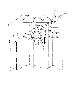
Figure 2 presents another perspective view of the door structure 100 of Figure
1
with the door 108 and a portion of the paneling 112 removed and illustrating a
portion of
a subframe 120 onto which the frame 104 and paneling 112 may be mounted and
secured
CA 02887754 2015-04-10
in any appropriate manner. For instance, the subframe 120 may include a
plurality of
structural members or components such as first and second (e.g., vertical and
parallel)
stud assemblies 124, 128 (e.g., each includes a king and/or jack stud of any
appropriate
materials and dimensions) and a header 132 (of any appropriate materials and
dimensions) appropriately interconnected between the first and second stud
assemblies
124, 128 to form a rough opening 136 into which the frame 104 may be inserted
and
disposed for attachment to the subframe 120.
More specifically, the frame 104 may include a plurality of framing members
such as first and second jamb members 140, 144 respectively attached (e.g.,
via fasteners
or the like) to inside surfaces of the first and second stud assemblies 124,
128 as well as a
cross member 148 that interconnects the first and second jamb members 140, 144
and
that is attached (e.g., via fasteners or the like) to a bottom surface of the
header 132 (e.g.,
where the cross member 148 is generally perpendicular to the first and second
jamb
members 140, 144 and/or at other angles thereto). In one arrangement, the
first and
second jamb members 140, 144 and cross member 148 may be mounted so as to
respectively extend past or otherwise protrude from front surfaces 125, 129,
133 of the
first and second stud assemblies 124, 128 and header 133. While the subframe
120 and
frame 104 have been discussed in the context of the door 108, the various
teachings
herein may also be applicable to subframes 120 and frames 104 for other
components
such as windows and the like. Furthermore, various details of the subframe 120
(e.g.,
how header 132 is secured to the first and second stud assemblies 124, 128,
how the
subframe 120 interconnects to the overall frame of a building or house, etc.)
and frame
104 (e.g., how the framing members are secured to the subframe 120, hinges and
door
stops of the first and second jamb members 140, 144, etc.) are not discussed
in the
interest of brevity.
In any event, one or more of the framing members of the frame 104 may include
a
groove (e.g., slot, depression, track, etc.) therealong for receipt of a
connection member
and a portion of a molding member as will be discussed in more detail below.
As shown
in Figure 2, for instance, the first and second jamb members 140, 144 and
cross member
148 may include respective grooves 141, 145, 149 at least partially
therealong. In one
11
CA 02887754 2015-04-10
arrangement, each of the grooves 141, 145, 149 may extend along a longitudinal
length
of its respective framing member, such as in an orientation in which a molding
member
(e.g., trim, etc.) is desired to be mounted relative thereto.
Turning now to Figure 3a, an exploded perspective view of a portion of the
structure of Figure 2 is presented, where the first jamb member 140 is
attached to the first
stud assembly 124 and the paneling 112 is secured over the first stud assembly
124. Also
illustrated is a connection member 152 (also see Figures 21a-21c) that may be
used to
secure a molding member 156 to the first jamb member 140 to allow the molding
member 156 to cover or conceal an interface 160 (e.g., gap, joint, abutment)
between the
first jamb member 140 and the paneling 112 (e.g., and/or between the first
jamb member
140 and the first stud assembly 124 in the event paneling 112 was not secured
over the
first stud assembly 124).
Broadly, the connection member 152 may be receivable in the groove 141 and
may serve to interconnect a projecting member 164 of the molding member 156 to
the
first jamb member 140 so that a cover member 168 of the molding member 156 may
conceal the interface 160 (e.g., where the projecting member 164 extends at an
angle
from the cover member, such as 90 , 120 , etc.). As shown, the connection
member 152
may include a body 172 (e.g., base member) having first and second opposite
surfaces
176, 180 (e.g., that are parallel to each other) as well as at least one
fastening apparatus
disposed on one of the first and second surfaces 176, 180, such as a first
fastening
apparatus 184 disposed on or connected to the first surface 176 and a second
fastening
apparatus 188 disposed on or connected to the second surface 180.
In one arrangement and as shown in Figure 3a, each of the first and second
fastening apparatuses 184, 188 may be in the form of a plurality of fasteners
192 (e.g.,
nails, staples, etc., such as four as shown in the figures or any other
appropriate number,
see embodiment of connection member 152"" in Figure 22) extending or
protruding
away from the first and second surfaces 176, 180, respectively (e.g., in
opposite
directions away from the first and second surfaces 176, 180). In one
embodiment, the
fasteners 192 may be substantially collinearly arranged on the surface(s) of
the base
member. In another embodiment, the fasteners 192 may be staggeredly arranged
on the
12
CA 02887754 2015-04-10
surface(s) of the base member 172. In another embodiment, each of the first
and second
fastening apparatuses 184, 188 may include two or more rows of collinearly
arranged
fasteners 192. In another embodiment, one or both of the fastening apparatuses
184, 188
may additionally or alternatively include an adhesive disposed over the first
and/or
second surface 176, 180 (e.g., such as an adhesive with a releasable cover
thereover,
where the cover could be removed before insertion of the connection member 152
into
the groove 141).
The connection member 152 may be constructed of any appropriate material(s)
(e.g., plastic, vinyl, wood, metals such as steel and/or magnetic material,
various
combinations thereof, and/or the like) to facilitate interconnection between
the molding
member 156 and the first jamb member 140 and/or other framing members and
building
components. As just one example, Figure 9 presents an exploded perspective
view of one
embodiment of an embodiment of the connection member 152'. As shown, the body
172
may include one or more strips (e.g., layers, plates, etc.) of any appropriate
material(s)
such as a first layer 175 (e.g., constructed of plastic or metal) that
includes the first
surface 176 of the body 172, a second layer 179 that includes the second
surface 180 of
the body 172, and an intermediate layer 181 (e.g., constructed of plastic or
metal such as
steel) for interconnecting the first and second layers 175, 179 as well as
providing
strength to the connection member 152.
As an example, each of the first layer 175, second layer 179 and intermediate
layer 181 may be initially formed in any appropriate manner. In the case of
the first and
second layers 175, 179, for instance, the various fasteners 192 may be secured
to the
layers during any appropriate molding process (e.g., insert molding, injection
molding) so
as to respectively project away from the first and second surfaces 176, 180.
Alternatively, a pre-formed sheet may be appropriately cut into the first and
second layers
175, 179 and then the fasteners 192 may be appropriately driven through the
first and
second layers 175, 179 until heads 193 of the fasteners 192 are in contact
with the first
and second layers 175, 179. The intermediate layer 181 may also be formed in
any
appropriate manner such as stamping, casting, cutting, and/or the like.
13
CA 02887754 2015-04-10
Once the various layers have been formed in any appropriate manner, the layers
may be interconnected to form a completed connection member 152. As one
example,
any appropriate adhesive 183 may be applied to opposite surfaces (not labeled)
of the
intermediate layer 181. The first layer 175 (e.g., the surface of the first
layer 175 on
which the heads 193 of the fasteners 192 are disposed) may then be put in
contact with
one surface of the intermediate layer 181 and the second layer 179 may be put
in contact
with the opposite surface of the intermediate layer 181 so that the fasteners
192 of the
first and second fastening apparatuses 184, 188 extend in opposite directions.
The
various layers may then be pressed and held together in any appropriate manner
until the
adhesive 183 has cured. As an alternative to the adhesive 183, the various
layers may be
heated (e.g., so as to melt or at least partially flow) and subsequently fused
together.
Various other manners of pressing, bonding, adhering, securing, etc. the
layers together
are envisioned and encompassed in the present disclosure.
In one arrangement, the connection member 152 may be in the form of a single
layer having opposite surfaces from which the fasteners 192 project. For
instance, the
various fasteners 192 may be seated directly into the single layer so as to
extend away
from the opposite surfaces of the single layer during any appropriate molding
process
(e.g., insert molding, etc.) of the single layer. As another example, the
single layer may
be constructed of metal or the like, where the various fasteners 192 may be
punched out
from opposite surfaces of the single layer and as seen in the embodiment of
the
connection member 152" of Figure 10. The various connection members 152
disclosed
herein may be constructed via any appropriate manual and/or automated
processes.
While the length of the fasteners 192 of the first fastening apparatus 184 is
illustrated in Figure 3a as being generally the same as that of the fasteners
192 of the
second fastening apparatus 188, some arrangements disclosed herein envision
that the
lengths may be different. See the embodiment of the connection member 152" in
Figure
11. This embodiment may be advantageous in arrangements whereby the fasteners
192
need to travel all the way through paneling (e.g., drywall) before piercing a
stud or other
structural member (e.g., such as in the embodiment illustrated in Figure 15
discussed
below). In some arrangements, one or more of the fasteners 192 may extend at
non-
14
CA 02887754 2015-04-10
perpendicular angles (e.g., 45 , 60 , etc.) relative to the surface from which
they extend.
In any case, and to mount the molding member 156 to the first jamb member 140
so as to
conceal the interface 160, the connection member 152 may be disposed (e.g.,
inserted)
into the groove 140 so that the first fastening apparatus 184 at least
partially engages a
surface that at least partially defines the groove 141 (e.g., such as an inner
back surface
208 of the first jamb member 140). To allow for insertion or disposal of the
connection
member 152 into the groove 141, a width 196 of the body 172 may be
substantially equal
to or less than a width 200 of the groove 141. Similarly, a width 204 of the
projecting
member 164 of the molding member 152 may be substantially equal to or less
than the
respective widths 196, 200 of the body 172 and the groove 141.
For instance, the connection member 152 may be forced into the groove 141
(e.g.,
via any appropriate tool) so that the fasteners 192 at least partially pierce
the back surface
208 to seat the connection member 152 in the groove. See Figure 4. In one
arrangement
and as shown in Figures 5a-5c, a tool 212 may be provided to insert and seat
the
connection member 152 in the groove 141. As shown, the tool 212 may include a
handle
216 having opposite first and second ends 219, 218 and a mounting head 220
rigidly
connected to the second end 218 of the handle 216. A longitudinal axis 217 may
extend
through the first and second ends 219, 218. The mounting head 220 may include
a
mounting surface 224 that includes a plurality of apertures 228 that are
respectively
configured to receive the fasteners 192 of the first and second fastening
apparatuses 184,
188. For instance, the mounting surface 224 may generally reside in a
reference plane
(not labeled) that is substantially perpendicular to the longitudinal axis
217. In an
arrangement, the plurality of apertures 228 may be arranged into a plurality
of rows of
apertures 228 for use in receiving a staggered arrangement of fasteners 192 of
a
connection member 152. In an arrangement, the apertures 228 may stop short of
extending all of the way through the mounting head 220 to form a bottom or
lower
surface against which the fasteners may be disposed.
In use, a user may grasp the connection member 152 and then align and at least
partially insert the fasteners 192 of the second fastening apparatus 188 into
the apertures
228 on the mounting surface 224 of the mounting head 220. See Figures 5a-5b.
The user
CA 02887754 2015-04-10
may then grasp the handle 216 of the tool 212 and insert the connection member
152 into
the groove 141. For instance, Figure 5c illustrates the tool 212 being used to
insert a
connection member 152 into the groove 149 of the cross member 148 (where the
tool 212
could be similarly used to insert the connection member 152 into the groove
141 of the
first jamb member 140 and/or the grooves of other framing members). As the
user
encounters resistance when the ends of the fasteners 192 of the first
fastening apparatus
192 begin engaging the back surface 208 of the groove 141, the user may
continue urging
the connection member 152 into the groove 141 against the encountered
resistance to
drive the fasteners 192 further through the back surface 208 and into the
first jamb
member 140. For instance, urging of the tool 212 may cause the mounting
surface 224 of
the mounting head 220 to engage and apply a corresponding force against the
second
surface 188 of the base 172 of the connection member 152 so as to drive the
fasteners
192 through the back surface 208 (e.g., such as until the first surface 184 of
the base
member 172 abuts or substantially abuts the back surface 208 of the groove
141).
In one embodiment, a single connection member 152 may be seated in the groove
141 as discussed above, where a length of the single connection member 152 may
or may
not be substantially the same as that of the groove 141 (e.g., from a first,
top end to a
second, bottom end of the groove 141). In another embodiment, a plurality of
shorter
connection members 152 may be seated in the groove as discussed above, where a
combined length of the plurality of shorter connection members 152 may or may
not be
the same as that of the groove 141. As just one example, a user may install a
first
connection member 152 adjacent one end of the groove 141, a second connection
member 152 adjacent a midpoint of the groove 141, and a third connection
member 152
adjacent an opposite end of the groove 141.
Once one or more connection members 152 have been seated in the groove 141 as
discussed above, the molding member 156 may be seated in the groove and
attached to
the connection member(s) 152 to mount the molding member 156 to the first jamb
member 140. For instance, and with reference to Figures 3a and 6, a user may
grasp the
molding member 156 and align the projecting member 164 with the groove 141.
The
user may then cause the projecting member 164 to be received in the groove 141
(e.g.,
16
CA 02887754 2015-04-10
via inserting the projecting member 164 into the groove 141) and engage with
the second
fastening apparatus 188 of the connection member 152. In one arrangement, the
user
may utilize a hammer or mallet (e.g., rubber mallet) to hammer or exert a
force on an
outside surface of the molding member 156 to cause the fasteners 192 of the
second
fastening apparatus 188 to pierce an end surface 232 of the projecting member
164.
Continued hammering or urging of the projecting member 164 into the groove 141
may
eventually result in sandwiching or compressing of the base member 172 of the
connection member 152 by the end surface 232 of the projecting member and the
back
surface 208 of the groove 141.
At this point, the first and second fastening apparatuses 184, 188 may be
respectively engaged with the first jamb member 140 and the projecting member
164
(e.g., the fasteners 192 are substantially seated in the projecting member 164
and the first
jamb member 140) thus securing the molding member 156 to the first jamb member
140.
See Figure 3b. Additionally, the cover member 168 of the molding member 156
conceals
or covers the interface 160. Use of the connection member 152 advantageously
inhibits
inadvertent dismounting or removal of the projecting member 164 (e.g., in a
direction
perpendicular and/or parallel to the back surface 208) and thus the molding
member 156
from the groove 141 (and thus the first jamb member 140). Furthermore, the
simultaneous placement or disposal of the projecting member 164 in the groove
141
increases lateral stability of the molding member 156, such as by limiting
side to side
movement of the molding member 156 in directions parallel to the front surface
of the
paneling 112.
The combined seating of the connection member 152 and the projecting member
164 in the groove 141 also facilitates intended removal of the molding member
156 from
the first jamb member 140 and thus separation from the paneling 112
substantially free of
damage to the molding member 156, paneling 112, and the like. With reference
to Figure
3b, for instance, a blade (e.g., paint scraper) or the like could be slid
between the cover
member 168 and the paneling 112 and then torqued (e.g., twisted) to separate
the molding
member 156 from the connection member 152. More specifically, the projecting
member
164 may serve as a cam that induces removal of the molding member from the
first jamb
17
CA 02887754 2015-04-10
member 140 and the paneling 112 in a direction that is substantially
perpendicular to the
paneling 112 in response to the torquing from the blade and/or other tool. As
a result, the
molding member 156 may be removed substantially free of damage (e.g.,
cracking)
occurring thereto.
It can be seen how the front of the first stud assembly 124 is set back with
respect
to the front of the first jamb member 140 or, in other words, how the front of
the first
jamb member extends past the front of the first stud assembly 124. In this
regard, a space
is provided that allows the paneling 112 to be mounted over the front surface
of the first
stud assembly 124 so that the front surface of the paneling is generally
parallel to or level
with the front of the first jamb member 140. Accordingly, the cover member 168
of the
molding member 156 is configured to cover the interface 160 when the
projecting
member 164 and connection member 152 are seated in the groove 141 as discussed
herein.
In other contexts, as seen in Figure 7a, a front surface of the paneling 112
may
extend past a front of the first jamb member 140. In one arrangement, the
molding
member 156 of Figure 7a could be designed or constructed so that its
projecting member
164 is longer (i.e., in a direction away from the cover member 168) than that
of the
molding member 156 of Figure 3a which would account for the front of the
paneling 112
extending past the front of the first jamb member 140 and thereby allow the
cover
member 168 to conceal the interface 160 while resting substantially flat
against the front
surface of the paneling 112.
In another arrangement, and as seen in Figure 7a, an extension member 236 may
be used that is configured to space the cover member 168 of the molding member
156
away from the first jamb member 140 to allow for use of the same molding
member 156
of Figure 3a as will be discussed in more detail below. Broadly, the extension
member
236 may serve as an adapter that is configured to interconnect the first jamb
member 140
to the molding member 156 and thus space the cover member 168 of the molding
member 156 away from the front of the first jamb member 140 so that the cover
member
168 can rest flat against the front surface of the paneling 112. In some
arrangements, the
extension member 236 may be considered a portion of the molding member 156 or
the
18
CA 02887754 2015-04-10
first jamb member 140 (or other framing member). For instance, the molding
member
156 may include first and second portions, where the member 156 is a first
portion and
the extension member 236 is a second portion. As another example, the first
jamb
member 140 may include first and second portions, where the member 140 is a
first
portion and the extension member 236 is a second portion.
In any event, the extension member 236 may include first and second opposite
sides, where the first side includes a projecting member 240 that is
configured to be
received in the groove 141 of the first jamb member 140, and where the second
side
includes a groove 244 that is configured to receive the projecting member 164
of the
molding member 156. In this regard, the projecting member 240 and a first
connection
member 1521 are configured to be received and seated in the groove 141 of the
first jamb
member 140 and the projecting member 164 and a second connection member 1522
are
configured to be received and seated in the groove 244 of the extension member
236.
In use, the first connection member 1521 may be inserted into the groove 141
so
that the first fastening apparatus 184 engages with the back surface 208 of
the groove 141
(e.g., via the tool 212 of Figures 5a-5c and/or in other manners) as discussed
previously.
The projecting member 240 of the extension member 236 may then be aligned with
and
inserted into or received in the groove 141 (e.g., via a rubber mallet or the
like as
discussed above) so that the second fastening apparatus 188 of the first
connection
member 1521 engages with an end surface 241 of the extension member 236. The
second
connection member 1522 may then be inserted into the groove 244 of the
extension
member 236 so that the first fastening apparatus 184 engages with a back
surface 245 of
the groove 244 (e.g., via the tool 212 of Figures 5a-5c and/or in other
manners). The
projecting member 164 of the molding member 156 may then be aligned with and
inserted into or received in the groove 244 (e.g., via a rubber mallet or the
like as
discussed above) so that the second fastening apparatus 188 of the second
connection
member 1522 engages with the end surface 232 of the molding member 156. See
Figure
7b. Figure 23 presents another embodiment of a molding member 156" being
inserted
into the extension member 236.
19
CA 02887754 2015-04-10
Figure 8 presents a top view of the embodiment of Figures 7a-7b but being
attached to the second jamb member 144. Furthermore, the second jamb member
144
includes first and second opposite grooves 1451, 1452 on opposite sides of the
second
jamb member 144. This arrangement advantageously allows for molding members to
be
secured to opposite sides of the frame 104 (labeled in Figure 1), such as for
an interior
door frame and/or the like. While only the second jamb member 144 has been
shown
with first and second grooves, it is to be understood that any of the framing
members
(e.g., the first jamb member 140, the cross member 148, etc.) could include
first and
second opposite grooves (e.g., in the embodiment of Figures 3a-3b, the
embodiment of
Figures 7a-7b, etc.) for purposes of facilitating the mounting of molding
members on
opposite sides of the framing members.
While much of the discussion herein was in relation to the first jamb member
140,
it is to be understood that the discussion may be equally applicable to other
framing
members (e.g., second jamb member 144, cross member 148) so as mount molding
members about an entirety or substantial entirety of a frame (e.g., of frame
104 of Figure
1). For instance, a connection member 152 may be inserted into and seated in
the groove
149 of the cross member, a projecting member 164 of a molding member 152 may
be
inserted into the groove 149 and engaged with the connection member 152, etc.
The molding members 156 can be mounted to frames in different orders than
those specifically discussed above. For instance, the second fastening
apparatus 188 of a
connection member 152 may be engaged with the end surface 232 of a molding
member
and then the projecting member 164 and connection member 152 may be inserted
into
and seated in the groove (e.g., the groove 141 in the embodiment of Figures 3a-
3b or the
groove 244 in the embodiment of Figures 7a-7b). In one arrangement, molding
members
156 may be provided or supplied with connection members 152 already secured to
the
projecting members 164 (e.g., via adhesives, fasteners, an integral
connection, etc.).
Furthermore, it is to be understood that the projecting member and groove
pairs of the
various systems and embodiments thereof disclosed herein may be arranged vice
versa.
In the embodiment of Figures 3a-3b, for instance, the projecting member 164 of
the
molding member 156 may be replaced with a groove and the groove 141 of the
first jamb
CA 02887754 2015-04-10
member 140 may be replaced with a projecting member. In this regard, the
connection
member 152 may be inserted into the groove of the molding member 156 or
engaged
with the end surface of the projecting member of the first jamb member 140,
and then the
projecting member of the first jamb member 140 be received in the groove of
the
molding member 156. In the embodiment of Figures 7a-7b, for instance, the
groove 141
and projecting member 240 could be replaced with a projecting member and
groove,
respectively, and the groove 244 and projecting member 164 could be replaced
with a
projecting member and groove, respectively.
The various connection members 152 need not necessarily be sandwiched (e.g.,
compressed) between a surface (e.g., back surface) of a groove and an end of a
projecting
member to interconnect a molding member over an interface of building or
structural
components. For instance, Figure 12 illustrates another system for mounting
molding
onto a frame of a door (or other structure such as a window, etc.) similar to
the system of
Figure 3a, but where the first jamb member 140' (e.g. or other framing member)
does not
include the groove 141 therein. Rather, the first jamb member 140' includes a
front
surface 142 through which the fasteners 192 of the first fastening apparatus
184 are
configured to pierce and against which the first surface 176 of the body 172
is configured
to engage or abut. As shown, the front surface 142 may be level with the front
surface of
the paneling 112. In this embodiment, a molding member 156' may include a
groove 157
(e.g., depression, track, etc.) therein into which the connection member is
configured to
be seated (e.g., via the fasteners 192 of the second fastening apparatus 188
piercing
through a back surface 158 of the groove 157).
Figure 13 illustrates another embodiment of the system similar to that shown
in
Figure 12 but that includes first and second connection members 1521, 1522
seated in the
groove 157 of the molding member 156'. For instance, the fasteners 192 of the
first
fastening apparatus 184 of the first connection member 1521 may be configured
to pierce
through the front surface 142 of the first jamb member 140' (or other framing
member)
while the fasteners 192 of the first fastening apparatus 184 of the second
connection
member 1522 may be configured to pierce through the paneling 112 and into the
first stud
assembly 124 (or other structural or building component).
21
CA 02887754 2015-04-10
In one variation, an individual connection member may be configured to
simultaneously engage with the first jamb member 140' (or other framing
member) and
the first stud assembly 124 (or other structural or building component). For
instance, the
connection member 152 of Figure 12 may be rotated 90 degrees (e.g.,
perpendicular to its
position shown in Figure 12) so as to cross over the interface 160 to allow
the fasteners
192 of the first fastening apparatus 184 to simultaneously engage with the
first jamb
member 140' and the first stud assembly 124. As another example, the
connection
member 152 of Figure 12 could, in the event that the fasteners 192 of the
first fastening
apparatus 184 staggeredly extend from the first surface 176 of the body 172,
be disposed
so as to substantially directly overlay the interface 160 so that at least
some of the
fasteners 192 engage with the first jamb member 140' and at least some of the
fasteners
192 engage with the first stud assembly 124. Figure 14 presents a perspective
view of
another embodiment of the system including another molding member 248 (e.g.,
baseboard) including a groove 249 on a backside thereof into which a
connection
member 152 may be received and seated. After the connection member 152 has
been at
least partially seated in the groove 249 (e.g., via the tool 212 of Figures 5a-
5c and/or in
other appropriate manners), the molding member 248 may be secured adjacent a
base of a
wall 252 (e.g., drywall or the like) as shown in Figure 15. For instance, the
molding
member 248 may be initially placed onto a top of a flooring surface 256 (where
the
flooring surface 256 is disposed over any appropriate subflooring 260).
Thereafter, the molding member 248 may be forced against the wall 252 (e.g.,
via
hammering the molding member 248 with a rubber mallet or the like) to drive
fasteners
192 of the connection member 152 through the wall 252 and into one or more
studs 264
or other structural members behind the wall 252 and thereby conceal an
interface 268
between the wall 252 and flooring surface 256. In one arrangement, the
connection
member 152 span a substantial entire length of the molding member 248 so that
at least
some of the fasteners 192 of the connection member 152 may engage with studs
264
(e.g., in the case where adjacent parallel studs are spaced apart by 16" or
the like). In
another arrangement, a plurality of smaller individual connection members 152
may be
22
CA 02887754 2015-04-10
respectively seated in the groove 249 of the molding member 248 and spaced
apart by the
same spacing between adjacent studs 264 or other structural members.
In some arrangements, the connection members 152 may be used to secure
molding members 156 and/or other members (e.g., decorative pieces) over
interfaces
(e.g., corners) between two non-parallel (e.g., perpendicularly-arranged) or
non-coplanar
building components. Turning now to Figure 16, another embodiment of the
system is
illustrated that is useful for mounting a molding member 272 (e.g., decorative
piece, etc.)
over an interface 280 between adjacent, perpendicular wall surfaces 276. At
least one
connection member 152" may be used whereby the fasteners 192 of the first
fastening
apparatus 184 are disposed at a non-perpendicular angle relative to the first
surface 176
of the body 172. For instance, the fasteners 192 of the first fastening
apparatus 184 of a
first connection member 1521" may extend at a positive 45 relative to the
first surface
176 of the body 172 while those of a second connection member 1522" may extend
at a
negative 45 relative to the first surface 176 of the body 172. See Figure 16.
In use, for example, the fasteners 192 of the second fastening apparatus 188
of the
first and second connection members 1521", 1522" may be driven into respective
first
and second surfaces 282, 283 of the molding member 272. While not shown, the
first
and second surfaces 282, 283 may include grooves (e.g., depressions, tracks)
as discussed
herein into which the connection members may be seated. In any event, the
molding
member 272 may then be aligned over the interface 280 and the fasteners 192 of
the
second fastening apparatus 188 of the first and second connection members
1521",
1522" driven into the adjacent walls 276 (e.g., via driving (e.g., hammering)
a hammer
or the like (e.g., rubber mallet) against a third surface 284 of the molding
member 272).
As shown, the connection members may be constructed or selected so that the
fasteners 192 being driven into the walls 276 are substantially perpendicular
to the
surface of the molding member 272 being hammered by the hammer or other tool
(e.g.,
the third surface 284). Stated differently, the fasteners 192 being driven
into the walls
276 may be angled so that they are oriented substantially parallel to the
direction of force
being applied by the hammer or other tool. This arrangement advantageously
facilitates
23
CA 02887754 2015-04-10
driving of the fasteners 192 into the walls 276 via increased transfer of the
force applied
to the third surface 284 to the fasteners 192 being driven into the walls 276.
While not shown, the system of Figure 16 could also be arranged vice versa
whereby the fasteners 192 disposed at the non-perpendicular angle to the body
172 are
engaged with (e.g., inserted into) the first and second surfaces 282, 283 of
the molding
member 272 rather than into the adjacent walls 276. For instance, the
fasteners 192 of
the second fastening apparatuses 188 of each of the first and second
connection members
1521"", 1522" may be appropriately driven into the adjacent walls 276 so that
the
fasteners 192 of the first fastening apparatuses 184 of each of the first and
second
connection members 1521", 1522" all extend away from the adjacent walls 276 in
a
direction that is substantially perpendicular to the third surface 284 and non-
perpendicular to the first and second surfaces 282, 283. Thereafter, the
molding member
272 may then be aligned over the interface 280 and the molding member 272
driven
against the fasteners 192 of the first fastening apparatuses 184 of the first
and second
connection members 1521", 1522" to pierce and drive the fasteners 192 into the
first
and second surfaces 282, 283 of the molding member 272 and mount the molding
member 272 against the walls 276 (e.g., and over the interface 280).
While Figure 16 illustrates use of the disclosed connection members to secure
a
molding member to an inside corner between two adjacent walls, the disclosed
connection members could also similarly be used to secure a molding member to
an
outside corner between two adjacent walls.
The body 172 of the various connections members 152 disclosed herein is not
necessarily limited to elongated layers or substantially planar members as
shown in the
drawings and various other shapes and sizes are envisioned and included herein
depending upon the particular end use. For instance, Figures 17a-17b
illustrate a
connection member 152" having a body 172 that is substantially circular while
Figures
18a-18b illustrate a connection member 152" having a body 172 that is
substantially
cross-shaped. As another example, the thickness of the body 172 of the
connection
member 152 may in some situations be greater than shown in the disclosed
drawings
(e.g., approaching its width). One or more combinations of the various systems
and
24
CA 02887754 2015-04-10
embodiments thereof disclosed herein may be combined into kits in any
appropriate
manner. For instance, one or more molding members (e.g., molding member 156
and/or
molding member 248) and/or connection members 152 may be supplied in the same
packaging for use in mounting molding to a door frame, window frame, base of a
wall,
and the like.
The various components disclosed herein may be manufactured in any appropriate
manner(s), shapes, sizes, dimensions, and material(s). For instance, Figure 24
presents
another embodiment of a molding member 156". Furthermore, while the frame 104
has
been discussed in the context of door and windows, it is to be understood that
the
disclosed systems may be utilized in numerous contexts in which it is desired
to cover or
conceal interfaces between structural components of a building via molding or
the like.
Still further, the connection members disclosed herein may be used to mount
various
members (e.g., decorative, molding, etc.) onto or over building components
(e.g., walls)
even when doing so does not cover an interface between building components
(e.g., in
the middle of a wall).
Still further, while the invention has been illustrated and described in
detail in the
drawings and foregoing description, such illustration and description is to be
considered
as exemplary and not restrictive in character. As an example, the connection
members
152 may additionally or alternatively in some embodiments be configured to
engage one
or both opposite side surfaces of the groove 141 (e.g., in addition to or
instead of the back
surface 208). In one arrangement, the body 172 may include one or more
fastening
apparatuses disposed on or extending from one or both opposite side surfaces
(not
labeled) of the body 172 (between the first and second surfaces 176, 180). For
instance,
one or more fasteners may extend away from one or both of the side surfaces
and be
disposed at an acute angle to the side surfaces in a direction away from the
first surface
176 and towards the second surface 180. This arrangement would facilitate
entry of the
body 172 into the groove 141 but inhibit removal of the body 172 from the
groove 141
(e.g., due to the fasteners on the side surfaces of the body 172 engaging with
the opposite
side surfaces of the groove 141).
CA 02887754 2015-04-10
In another embodiment, the fasteners 192 of one of the first and second
fastening
apparatuses 184, 188 of the connection member 152 may be in the form of screws
having
threads that are configured to be threaded into the molding member 156 or
framing
member (or other component). With reference to Figure 3a, for instance, assume
the
fasteners 192 of the first fastening apparatus 184 are screws and that the
heads of the
screws are accessible via the second surface 180 of the body 172. Also assume
the
fasteners 192 of the second fastening apparatus 188 are nails as shown (e.g.,
where the
nails would not be disposed directed over the screws to allow for access to
the screw
heads). In this regard, the connection member 152 could be inserted into the
groove 141
and a tool (e.g., screwdriver, drill) could be engaged with the heads of the
screws to
thread the screws into the back surface 208 of the groove 141 (e.g., which may
be
preceded by drilling corresponding holes into the back surface 208).
Thereafter, the
projecting member 164 of the molding member 156 could be aligned, inserted,
and
forced into the groove to engage with the fasteners 192 of the second
fastening apparatus
188 as discussed previously.
In another embodiment, the tool 212 of Figures 5a-5c may be used to insert
fasteners (e.g., fasteners 192) into molding members (e.g., molding members
156,
molding members 272, etc.), framing members (e.g., first jamb member 140),
etc. free of
the base member 172 of the connection members 152. Stated differently, the
tool 212
may in some situations be used to insert loose fasteners into molding members,
framing
members, and the like. With reference to Figures 19-20, for instance, one or
more
fasteners 192 (e.g., nails, pins, etc.) may be respectively inserted into one
or more of the
apertures 228 through the mounting surface 224 of the mounting head 220. A
user may
then grasp the handle 216 and use the tool 212 to drive the fasteners 192 into
a surface of
a molding member, framing member (e.g., the back surface of a groove, a front
surface
when no groove is present, etc.), and/or the like. The user may then take the
molding
member or the like, dispose the same against a framing member, wall, panel,
etc., and
forcibly drive (e.g., hammer) the molding member against the framing member,
wall,
panel, etc. to drive the fasteners into the framing member, wall, panel, etc.
and thereby
mount the molding member thereover.
26
CA 02887754 2015-04-10
While this disclosure contains many specifics, these should not be construed
as
limitations on the scope of the disclosure or of what may be claimed, but
rather as
descriptions of features specific to particular embodiments of the disclosure.
Certain
features that are described in this specification in the context of separate
embodiments
and/or arrangements can also be implemented in combination in a single
embodiment.
Conversely, various features that are described in the context of a single
embodiment can
also be implemented in multiple embodiments separately or in any suitable
subcombination. Moreover, although features may be described above as acting
in
certain combinations and even initially claimed as such, one or more features
from a
claimed combination can in some cases be excised from the combination, and the
claimed
combination may be directed to a subcombination or variation of a
subcombination.
The embodiments described hereinabove are further intended to explain best
modes known of practicing the invention and to enable others skilled in the
art to utilize
the invention in such, or other embodiments and with various modifications
required by
the particular application(s) or use(s) of the present invention. It is
intended that the
appended claims be construed to include alternative embodiments to the extent
permitted
by the prior art.
The foregoing description of the present invention has been presented for
purposes of illustration and description. It is to be understood that the
drawings are not
necessarily drawn to scale. Furthermore, any use of "first," "second," etc.
(e.g., first jamb
member, second jamb member, etc.) is merely for purposes of facilitating the
reader's
understanding of the invention and does not preclude a component labeled as a
"first"
component from being the "second" component and vice versa. Still further, the
description is not intended to limit the invention to the form disclosed
herein.
Consequently, variations and modifications commensurate with the above
teachings, and
skill and knowledge of the relevant art, are within the scope of the present
invention.
27