Note: Descriptions are shown in the official language in which they were submitted.
CA 02887796 2015-04-09
PCT/EP2013/070510 - 1 -
2012P23865WOUS
Description
Method for the flexible operation of a power plant
The invention relates to a method for the flexible operation of
a power plant with a waste heat steam generator which works
according to the once-through principle.
Modern power plants are required to be not only highly
efficient but also as flexible as possible in operation. This
includes, as well as short start-up times and high load-change
speeds, also the possibility of equalizing frequency
disturbances in the network. Depending on the requirement
profiles of individual networks of different countries and the
associated remuneration models, it can therefore be expedient,
in particular in the case of combined gas and steam power
plants, to make additional power available to the network as
quickly as possible during peak load operation via the steam
circuit by means of an additional firing. Such gas and steam
power plants with additional firing are known for example from
DE 10 2010 060 064 Al, EP 1 050 667 Al and US 3,980,100.
In currently known power plants with additional firing,
generally use is made of drum-type boilers. Here, there is a
noticeable delay between the additional firing being activated
and the quantity of steam produced in the evaporator
increasing. The improvement in the steam cooling of affected
heating surface pipes, which cooling is directly coupled to the
transient behavior of the steam production, is also delayed. In
concrete terms, this means that, immediately at the point when
the additional firing is switched on, superheater surfaces and
reheater surfaces have to at first cope with the increasing
heating on the flue gas side with approximately identical steam
flow. Conversely, however, this also means that the fluid
temperatures - and thus also the wall temperatures - of these
heating surfaces can be held within permissible limits only by
CA 02887796 2015-04-09
PCT/EP2013/070510 - la -
2012P23865WOUS
limiting the power increase of the additional firing. Such a
requirement,
' 81786539
- 2 -
however, substantially restricts the flexibility of the plant.
The invention has the object of providing a method which
overcomes the above-described drawbacks.
According to one aspect of the present invention, there is
provided a method for the flexible operation of a power plant,
the power plant including a waste heat steam generator that
works according to a once-through principle and has a plurality
of heating surfaces of various stages of the waste heat steam
generator arranged in a flue gas duct, the method comprising:
increasing power of the power plant by using an additional
firing power controller controlling an additional firing within
the flue gas duct at approximately the same time as a mass flow
rate of a feed water flowing through the plurality of heating
surfaces is increased by controlling a feed water quantity
controller controlling a feed water pump, the additional firing
power controller and the feed water quantity controller both
being controlled and monitored by a central control system,
wherein the additional firing is located at a flue gas entry
side of the flue gas duct; wherein the feed water flows in a
feed water direction towards the flue gas entry side of the
flue gas duct starting proximate a flue gas exit side of the
flue gas duct through the plurality of heating surfaces a
single time according to the once-through principle; wherein a
flue gas flows from the flue gas entry side of the flue gas
duct and around the plurality of heating surfaces, such that
the flue gas first passes around one or more superheater
stages, then around one or more evaporator stages, and then
around one or more preheater stages, in a flow direction
opposite to a flow direction of the feed water.
CA 2887796 2019-12-16
81786539
- 2a -
According to another aspect of the present invention, there is
provided a method for flexible operation of a power plant
having a waste heat steam generator that works according to a
once-through principle, the waste heat steam generator
including a plurality of heating surfaces of various stages of
the waste heat steam generator arranged in a flue gas duct, the
method comprising: switching on an additional firing that is
arranged in the flue gas duct; and increasing a mass flow rate
of a feed water flowing through the plurality of heating
surfaces by controlling a feed water quantity controller
controlling a feed water pump when the additional firing is
switched on using an additional firing power controller
controlling to increase a steam mass flow rate that: actively
controls a cooling of one or more superheater heating surfaces
of the plurality of heating surfaces within the flue gas duct,
and generates a larger quantity of steam to be delivered;
wherein the feed water flows in a feed water direction towards
a flue gas entry side of the flue gas duct starting proximate a
flue gas exit side of the flue gas duct through the plurality
of heating surfaces a single time according to the once-through
principle; wherein a flue gas flows from the flue gas entry
side of the flue gas duct and around the plurality of heating
surfaces, such that the flue gas first passes around one or
more superheater stages, then around one or more evaporator
stages, and then around one or more preheater stages, in a flow
direction opposite to a flow direction of the feed water; the
additional firing power controller and the feed water quantity
controller both being controlled and monitored by a central
control system.
CA 2887796 2019-12-16
81786539
- 2b -
By using an additional firing, which is in particular arranged
in the superheater/reheater region of the flue gas dug of the
waste heat steam generator, the heat power transmitted to the
steam circuit increases, which increases the quantity of steam
generated and finally also the mechanical power delivered by
the steam turbine. However, it is to be taken into account in
this context that flue gas temperatures increase significantly
in the flue gas duct in the vicinity of the additional firing
which has been brought on-line. Especially the first heating
surfaces downstream of the additional firing in the direction
of the flue gas (these are generally the high-pressure
superheater heating surfaces) are in these situations exposed
to high thermal load. However, sufficient pipe cooling of these
heating surfaces is essential if one is to ensure safe long-
term operation. Finally, this pipe cooling is to be provided by
means of the quantity of steam produced in the evaporator if
one wishes to avoid the use of further components, such as
additional injection coolers, which ensure sufficient pipe
cooling of the corresponding heating surfaces in the flue gas
duct. However, since the production of steam in the evaporator
increases only with a noticeable delay after the additional
firing is switched on, the superheater is exposed, at least
immediately after the additional firing is brought on-line, to
substantially greater heating while the pipe cooling properties
remain largely the same, with all the resulting consequences.
CA 2887796 2019-12-16
CA 02887796 2015-04-09
PCT/EP2013/070510 - 3 -
2012P23865WOUS
It is therefore provided according to the invention that, for
the flexible operation of a power plant with a waste heat steam
generator which works according to the once-through principle
and has heating surfaces of various pressure stages of the
waste heat steam generator arranged in the flue gas duct, in
order to increase power at approximately the same time as an
additional firing, arranged in the flue gas duct of the waste
heat steam generator, is brought on-line, the mass flow rate of
the feed water flowing through the heating surfaces is
increased.
The core idea of the present invention lies in using the
techno-physical advantage of once-through systems as compared
to drum-type systems. The invention uses the system properties
of the once-through system which are not available to a system
with drum-type evaporators. This system property represents a
substantial advantage for power plants with waste heat steam
generators with additional firing integrated in the flue gas
duct, since the cooling of highly heated superheater heating
surfaces can be actively influenced by controlling the feed
water. Thus, in comparison to drum-type boilers, the once-
through system which is in any case trimmed to flexible
results, by virtue of the additional firing and the
simultaneous feed water control which is matched thereto, in
still greater plant flexibility. Furthermore, raising the steam
mass flow rate lowers the relevant maximum temperature for the
configuration of the superheater. This also allows the
superheater arranged downstream of the additional firing to be
fitted out with more cost-effective materials.
An advantageous development of the present invention relates to
the inherent protection of the evaporator itself. Actively
lowering the superheater baseline setpoint value at the
evaporator outlet when the additional firing is switched on
makes it possible to better withstand the greater heating of
the evaporator pipes which results from the additional firing.
CA 02887796 2015-04-09
PCT/EP2013/070510 - 3a -
2O1223865WOUS
Here, too, increasing the flow through the evaporator results
in better pipe cooling. One possible form of a control
particularly well suited thereto
CA 02887796 2015-04-09
PCT/EP2013/070510 - 4 -
2012P23865W0US
can be found in EP 2 194 320 Al.
If, after the additional firing is brought on-line, the actual
superheating at the evaporator outlet is to be reduced even
faster, or if the necessary increase in the steam mass flow
rate does not result quickly enough in an improved cooling - in
particular of the superheater - it is possible to provide an
additional pilot control signal which further increases the
feed water mass flow rate. Preferably, to that end, the power
increase of the additional firing is evaluated by means of a
DT1-derivative lag element and is added as an additional factor
on the feed water quantity signal. In order that an additional
signal is produced only in the case of transient processes of
the additional firing - caused by the character of such a DT1-
derivative lag element - this is not changed with the feed
water mass flow rate signal in the case of deactivated
additional firing or in the case of constant additional fire
power.
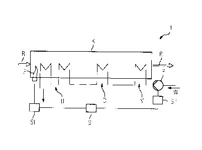
The invention will now be explained by way of example with
reference to a figure. The waste heat steam generator 1
depicted very schematically in the figure works according to
the once-through principle. Such a waste heat steam generator
usually has one or more preheater stages V, one or more
evaporator stages D and one or more superheater stages U. The
heating surfaces of the individual stages are arranged in a
flue gas duct K such that the hot flue gas R issuing for
example from a gas turbine flows first around the heating
surfaces of the superheater stages U, then those of the
evaporator stages D and finally those of the preheater stages
V. In each stage there results a transfer of heat from the flue
gas R to a medium flowing through the heating surfaces. With
respect to a flow medium, a feed water pump P is connected
upstream of the heating surfaces of the preheater stage V and
the heating surfaces of the evaporator stage D are connected
downstream thereof. The outlets of the heating surfaces of the
CA 02887796 2015-04-09
PCT/EP2013/070510 - 4a -
2012P23865WOUS
evaporator stage D can be connected, with respect to the flow
medium, via a water separator (not shown in more detail) to the
downstream superheater heating
CA 02887796 2015-0.1-09
PCT/EP2013/070510 - 5 -
2012P23865WOUS
surfaces U which, for their part, can be provided with
injection coolers for adapting the temperature of the steam
leaving the superheater heating surfaces.
In this case, the waste heat steam generator 1 is configured
for a controlled charge of feed water W. To that end, the feed
water pump P is controlled by means of a feed water quantity
controller SP such that the quantity of feed water or the feed
water mass flow rate urged by the feed water pump P towards the
preheater V can be set by means of a suitable control. One
possible form of such a feed water quantity controller SP can
be found for example in EP 2 194 320 Al. In the exemplary
embodiment shown here, the additional firing F is provided in
the flue gas duct K in the region of the heating surfaces of
the superheater U or other possible reheater heating surfaces.
The additional firing F is controlled - and in particular
switched on and off - by means of a corresponding additional
firing power controller SF. In order to carry out the method
according to the invention, both the additional firing power
controller SF for the additional firing F and the feed water
quantity controller SP for the feed water pump P are
accordingly controlled and monitored by a controller S such as
a central control system of the power plant.
Once-through systems have the decisive advantage over
circulating evaporators that, in normal operation, the flow
medium is already superheated at the outlet of the evaporator.
If according to the method according to the invention the feed
water mass flow rate is now simultaneously increased already
when the additional firing is switched on, this results, in the
case of a once-through evaporator, directly in a simultaneous
rise in the steam mass flow rate. This takes place at the
expense of the superheating, which is reduced by this measure.
As the steam mass flow rate increases, the pipe cooling
properties in the superheater are also simultaneously improved.
It is thus possible, with a once-through system, for the
CA 02887796 2015-04-09
PCT/EP2013/070510 - Sa -
2012P23865WOUS
superheater to be better cooled with increasing steam mass flow
rates already when the additional
CA 028796 2()15-009
4
PCT/EP2013/070510 - 6 -
2012P23865WOUS
firing is switched on. It is to be taken into account that,
theoretically, the increase in the steam mass flow rate by
increasing the quantity of feed water is only possible as long
as the flow medium at the evaporator outlet has not yet reached
the saturation temperature. If this is the case, any further
increase in the feed water mass flow rate leads to a rise in
the water produced in the bottle. Since, however, the extra
heating of the additional firing can also be felt in the
evaporator after a certain time delay, the reaching of the
saturation temperature is counteracted from this side.
The idea of the present notification of invention now relates
specifically to this techno-physical advantage of once-through
systems. The additional firing is generally, on account of its
property of worsening the overall efficiency of the plant, only
switched on when the plant power has already reached 100% and
additional power is to be made available at high remuneration
conditions. The system is such that, at 100% plant load, the
highest superheating is at the evaporator outlet of waste heat
steam generators 1 with BENSON evaporators. In current
configurations, this is between approximately 40 K and 50 K.
If, now, when the additional firing F is switched on, the
superheating baseline setpoint value of the evaporator D in the
feed water setpoint value determining of such once-through
waste heat steam generators is simultaneously reduced to its
minimum value (typically 10 K) within a very short time, then
on account of this measure the quantity of feed water flowing
through the evaporator increases. The feed water control
attempts to set the new superheating setpoint value by means of
an increased feed. Simultaneously, the steam mass flow rate
leaving the evaporator also increases, which steam mass flow
rate improves the cooling properties of the superheater stage U
which is highly loaded because of the additional firing. The
cooling effect in the superheater is even further increased by
virtue of the fact that the superheating at the evaporator
outlet has been reduced by the now increased quantity of feed
CA 02887796 2015-04-09
4
PCT/EP2013/070510 - 6a -
2012P23865WOUS
water. Since a minimum superheating baseline setpoint value of
K maintains a sufficient margin with respect to the
CA 02887796 2015-04-09
PCT/E22013/070510 - 7 -
2012P23865W0US
bubble-point curve, production of water in the water separator
need not be taken into account even in the case of minor
undershoots of the actual superheating at the evaporator
outlet. This is further supported by the fact that, as a result
of the increasing heating of the evaporator due to the
additional firing F, the actual superheating at the evaporator
outlet tends to climb further.