Note: Descriptions are shown in the official language in which they were submitted.
CA 02888131 2015-04-10
WO 2014/068450
PCT/IB2013/059576
- 1 -
TITLE
AN APPARATUS AND METHOD FOR WEEDING A MULTILAYER SHEET
COMPRISING A SUPPORT LINER AND AT LEAST ONE ADHESIVE FILM
COUPLED WITH THE LINER
DESCRIPTION
Technical field of the invention
The present invention concerns the field of graphic apparatuses and in
particular
its object is an apparatus and a relative method for the so-called "weeding"
of plastic or
paper films having or more self-adhesive, double sided adhesive or
electrostatic layers
Coupled with a support liner treated with a non-stick agent.
Background of the invention
In the preparation of adhesive graphics, simply decorative or also having a
protective function, obtained through various printing or through simple
engraving
processes, a distribution of single graphics is obtained on a single sheet
comprising
films of the type indicated above, printed and/or cut, coupled with a
supporting silicone
release paper, or liner. A cutting machine thus has the function of cutting
the fringes of
the various programmed drawings or writings only on the film, without however
cutting
also the support/release paper. At this stage there is the need of removing
the
"weeds", that is, the parts of adhesive film which are not processed and are
therefore
outside the graphics. In fact, the subsequent user, for his production
requirements,
needs to have a sheet in which there are only the graphics on the support
paper, so
that the same graphics can be easily removed and applied as desired.
Such a removal operation of the superfluous film, on the whole also called
"weed" for the sake of simplicity, is in fact called weeding. This is a very
onerous
operation and at the same time delicate since, especially when the contours of
the
graphics have irregular shapes, or in any case they have indentations or acute
curves
or undercuts (situation which occurs even with simple alphanumerical
characters), the
film of weed to be removed tends to tear, leaving residues, or to pull away
also the
graphical part that should instead be left unaltered. There are also often
small parts,
typically the internal hollows of characters and writings in general, which
require
operations that are accurate, precise and repeated.
- 2 -
Such an operation is currently carried out in a completely manual manner, with
serious affection of the production time and on labor costs. Automation of the
weeding
process, despite the attempts made, has been found to be problematic, indeed
for the
difficulties mentioned above, furthermore enhanced by the fact that the
different
graphics to be treated and their distribution demand requirements that are
always
different.
Summary of the invention
The present invention, on the other hand, provides a response to this strongly
felt
need, by providing a series of surprisingly effective technical expedients
that make
possible to achieve a weeding system that obtains a fully effective result,
capable of
replacing the manual methods currently in use, with consequent remarkable
advantages.
In accordance with an aspect of the present invention, there is provided a
weeding
apparatus for weeding a multilayer sheet having a support liner and at least
one
adhesive film coupled with the liner, the film having a plurality of graphic
elements
peripherally encircled by cuts and a weed among the graphic elements. The
apparatus
has a sheet support plane defining a sheet feeding direction; a fine weeding
device
adapted to work on the plane to individually remove parts of the weed
delimited by
respective closed cut boundaries; a rough weeding device adapted to remove in
a
single passage according to a rough weeding direction a unitary main part of
the weed;
and control means adapted to acquire and/or receive and/or store information
on the
shape and distribution on the sheet of the weed parts delimited by closed cut
boundaries, and to control the operation of the fine weeding device as a
function of the
information. The apparatus further has weed analysis means and cutting means
for
analyzing the shape and distribution of the graphic elements. The analysis and
cutting
means are adapted to transmit the information to the control means, wherein
the
analysis and cutting means are adapted to map and execute weeding assisting
cuts
that cut the weed intersecting with one or more edges of the graphic elements.
CA 2888131 2020-02-20
-2a-
In some embodiments, the weeding assisting cuts include cuts adapted to
increase
the number of parts of the weed that are defined by closed cut peripheries, to
be
removed by the fine weeding device.
The assisting cuts may include single blind cuts in correspondence with
respective
sharp corners formed by the graphic elements, having a vertex pointing
opposite to a
removal direction followed by the rough weeding device.
The analysis means can be adapted to map on the weed, in sequence,
distributions
of global assisting cuts that run between different graphic elements, and
distributions
of local assisting cuts that edge single graphic elements.
In certain embodiments, a search of points between which a global cut is to be
inserted includes: determining, for each graphic element, how many and which
other
elements are close or adjacent to the element; identifying and characterizing
the mutual
positioning between the adjacent elements; choosing for the execution of a
global cut
the space between two elements completely opposed to each other with respect
to a
predetermined direction, the opposed elements being such that, when drawing
two
straight lines parallel with such direction and passing for respective ends of
the
reference elements, the other element is an element intersected by both lines;
replacing the elements that are partially opposed to each other, the partially
opposed
elements being elements not intersected by both the straight lines, with
elements
having a barycenter at a minimum distance from the barycenter of the reference
element; setting the end points of each global cut in proximity to ends of the
resulting
chosen couples of elements; and extracting and storing information on weed
polygons
to be removed resulting from the cuts.
Mapping of the local cuts may include: analyzing all the graphic elements that
were
not previously joined to other elements with any global cut; identifying a
complex
envelope polygon of the graphic element under consideration; retrieving the
intersection of such polygon with the graphic element to obtain information on
the
concavity of the element; determining if the concavity, on the basis of the
rough
weeding direction, can cause rips in the weed, or if undercuts are formed and
so it
becomes necessary to proceed with a local cut; to this latter purpose,
identifying four
points of the graphic element that correspond respectively to the top left
point, top right
point, bottom left point and bottom right point; ordering clockwise the vector
of the
points, so that the bottom left point be in first position, to determine the
position of the
CA 2888131 2020-02-20
-2b-
concavity; determining and analyzing points of the periphery of the concavity
wherein
a change of direction with respect to a reference axis can be noticed, to
establish the
geometry of the concavity; determining, as a function of the result of the
previous steps
and of the rough weeding direction, the concavity areas in undercut
arrangement; for
each area of concavity in undercut arrangement, carrying out a local cut.
In some embodiments, the analysis means are adapted to identify pinching
points
where the weed parts are to be pinched by the fine weeding device, the weeding
device
having a determined working span, so as: once set a circumference on the basis
of the
working span of the fine weeding device, choosing parts having a sufficient
extension
in relation with such circumference; if a part has a concavity, choosing the
pinching
point along the boundary cuts of each part such that the circumference be
tangent to
the boundary cuts and internal to the weed part to be removed; or, if a part
has a convex
shape, choosing the pinching point in a substantially barycentric position.
Based on the size of the parts of the weed to be removed and on the pinching
point,
the analysis means may be adapted to retrieve and transmit control information
on the
movement that the fine weeding device has to carry out for weeding the sheet.
The
control information may include, in case of a barycentric pinching a lifting
movement
away from the sheet support plane or, in case of a peripheral pinching, a
displacement
over the plane towards the barycenter of a graphic element under consideration
and
then a lifting for the removal.
In certain embodiments, the rough weeding device includes a seizing head
extending above the plane along a transverse direction crosswise with respect
to the
sheet feeding direction, support and drive means adapted to drive the seizing
head at
least according to the feeding direction, wherein the seizing head is adapted
to emit a
pressurized air ejection substantially parallel with and adjacent to the plane
with an
ejection direction concordant with the feeding direction, and includes seizing
means
having in turn at least one pair of seizing members adapted to seize the weed,
whereby
a relative motion between the seizing head and the sheet is adapted to detach
the
weed from the support liner, the air ejection providing for a stabilization
and control of
the weeding action. The device further has cutting means arranged along the
transverse direction, flush within the plane and adapted to cut only the
supporting liner
to realize a sheet flap foldable upwards, to assist the engagement with the
seizing
head, and folding means associated with the cutting means and adapted to be
lifted
from the plane in order to fold the flap.
CA 2888131 2020-02-20
-2c-
In some embodiments, the pressurized air ejection extends over the whole width
of
the plane concordantly with the sheet feeding direction, due to an elongated
air ejection
blade with a plurality of side by side sectors controlled by respective
electrovalves
adapted to be operated selectively and independently.
The seizing members may include a pair of rollers having axis extending along
the
transverse direction, spaced with respect to the feeding direction and
arranged so that
the blade is substantially tangent to them. The pair may have a rear roller
with a fixed
axis and a front roller the axis of which is displaceable close to and away
from the rear
roller. The operation of the rollers may be coordinated with the relative
movement
between the head and the plane according to the feeding direction. The rear
roller may
be made of a silicone material, while the front roller is made of a metallic
material with
a non-stick coating.
In certain embodiments, the seizing means includes above the rollers and the
blade
a pull drum displaceable along with the rollers and the blade according to the
relative
movement in the feeding direction, the pull drum having in turn again a
transverse axis
and an incomplete development, that is, lacking of a circular sector, so as to
define a
radial face cooperating with a clamp for seizing and pulling the detached
weed, a shaft
for collecting the weed in a reel being provided above the pull drum, the
shaft being in
turn displaceable according to the feeding direction with the rollers and the
blade, but
also displaceable close to and away from relative to the pull drum, the drum
and the
shaft being motorized in a mutually independent manner.
The seizing head may have a slider supporting the seizing members, the slider
being movable on linear guide means along a direction orthogonal with the
plane, the
linear guide means being defined by a portal that rises from the plane and is
movable
with respect to it according to the feeding direction, dragging therewith the
blower
blade. An idle roller may be associated to the blade, adapted to press the
sheet against
the plane. In certain embodiments, the portal further supports in a movable
manner
along the linear guide means a weed collecting unit for collecting the weed
detached
by the seizing members.
In some embodiments, the fine weeding device includes: a gripper with a
pinching
head having an axial-symmetric development around a central axis, the head
having a
plurality of self-centering jaws radially movable close to and away from the
central axis,
and respective pinching means adapted to pinch portions of the weed, mounted
on the
jaws, wherein the pinching means have for each jaw respective blocks having
front
CA 2888131 2020-02-20
-2d-
facets, protruding frontwards from the corresponding jaw, adapted to match in
mutual
contact between the different blocks in a closed position of the head, the
front facets
having an axial extension such that, in cooperation with a slanting wall of
the block, a
pyramidal projection is formed with a shaped prismatic tip for gripping the
weed. The
tip may have an elevation, measured along the axis of the device and starting
from the
slanting wall from which it branches off, of between three and eight tenths of
millimeter.
There may be provided three jaws mutually angled at 120 , each block having a
couple of front facets in turn forming an angle of 120 with each other. The
jaws may
be mounted on, and driven by, a self-centering chuck, the jaws having
respective bases
for connection with the chuck and struts that axially project from the bases
for
supporting, at the free ends, respective pinching blocks.
In certain embodiments, the pinching head is mounted on a damper adapted to
ensure the exertion of a constant pressure on the material to be worked, the
damper
having elastic means elastically opposing the movement of a stem to which the
head
is connected. The head may have a ring-like tool supporting flange adapted to
be
coaxially and releasably connected, through fast joint means, to the stem of
the
damper, pegs being further provided radially projecting from the flange,
whereby, once
released from the stem, the flange is adapted to be held via the pegs in a
tool
replacement station.
In some embodiments, the apparatus has the sheet support plane; support means
for the gripper adapted to keep the gripper substantially orthogonal with the
support
plane; drive means adapted to move the pinching head in a Cartesian orthogonal
system defined by the support plane and by the central axis orthogonal with
the support
plane.
The apparatus may have two or more grippers arranged in a carousel fashion to
hide an unloading step of the removed weed by a gripper in an unloading
position, with
respect to another gripper in a pinching position, shelf means being further
provided,
integral with the support means and arranged close to the grippers to collect
the
unloaded weed. The carousel arrangement may have a revolving plate driven into
rotation around an axis parallel with the central axis of each gripper by
actuation
means, the grippers being mounted on the revolving plate with a linear
reciprocating
degree of freedom along the respective central axis of the grippers. The
apparatus
may have an elastic pusher secured with the plate acting on a tail of the
gripper in a
pinching position to calibrate the force applied in the pinching step, springs
being
CA 2888131 2020-02-20
-2e-
arranged between the grippers and the plate in order to compensate for the
variations
in height between the pinching position and the unloading position.
The apparatus may have air ejection means arranged close to the jaws of a
gripper
to assist the detach of the weed in an unloading stage.
In certain embodiment, the apparatus may have a slidable adhesive belt for
collecting the unloaded weed.
In accordance with another aspect of the present invention, there is provided
a
method for weeding a multilayer sheet comprising a support liner and at least
one
adhesive film coupled with the liner, the film having a plurality of graphic
elements
peripherally encircled by cuts and a weed among the graphic elements. The
method
includes: singularly removing parts of the weed delimited by respective closed
cut
boundaries; removing in a single passage a unitary main part of the weed
external to
the parts delimited by respective closed cut boundaries; acquiring and/or
receiving
and/or storing information on the shape and distribution on the sheet of the
weed parts
delimited by closed cut boundaries, and removing singularly the weed parts
delimited
by closed cut boundaries as a function of the information, wherein the shape
and
distribution of the graphic elements are analyzed, and weeding assisting cuts
that cut
the weed intersecting with one or more edges of the graphic elements are
executed on
the weed.
In some embodiments, the weeding assisting cuts include cuts adapted to
increase
the number of parts of the weed that are defined by closed cut peripheries, to
be
removed singularly. The assisting cuts may include single blind cuts in
correspondence with respective sharp corners formed by the graphic elements,
having
a vertex pointing opposite to a removal direction of the main part of the
weed.
Pinching points of the single weed part defined by closed cut boundaries may
be
determined so that: if a part has a concavity, choosing the pinching point
along the
boundary cuts of each part; or, if a part has a convex shape, choosing the
pinching
point in a substantially barycentric position; and wherein in case of a
barycentric
pinching, the removal of the weed part occurs with a lifting movement away
from the
sheet support plane or, in case of a peripheral pinching, it occurs with a
displacement
over the sheet plane towards the barycenter of the figure under consideration
and then
with a lifting for the removal.
CA 2888131 2020-02-20
-2f-
Brief description of the drawings
Characteristics and advantages of the weeding apparatus and method according
to
the present invention will become apparent from the following description of
embodiments thereof, made purely by way of example and not limitative, with
reference
to the attached drawings in which:
- figure 1 is a schematic axonometric view of an automatic weeding apparatus;
- figure 2 is a top plan view of the apparatus;
- figure 3 is an axonometric view from below of a gripper of a fine weeding
device
that according to the invention is included in the apparatus;
- figures 4 and 5 are axonometric exploded views of respective parts of the
gripper
of figure 3, in particular a damper and a pinching head;
- figure 6 is an exploded view of a radial jaw of the pinching head of
figure 5;
- figures 7a and 7b show respectively from a side and from above a pinching
block
of the jaw of figure 6;
- figure 7c is an enlarged detail of the inside of circle C of figure 7a;
CA 2888131 2020-02-20
- 3 -
- figure 8 and figure 9 schematically depict, respectively in an axonometric
view
and in front view, a fine weeding device according to a different embodiment
of the
invention;
- figure 10 and figure 11 represent, respectively in an axonometric and a side
view, a cutting device used in the apparatus according to the invention;
- figure 12 is a sectional view taken along a longitudinal plane of the
apparatus of
a seizing head of a rough weeding device according to the invention;
- figures 13 and 14 are, respectively, a front view and a top plan view of a
blower
of the rough weeding head of figure 12;
- figures from 15 to 17 are cross-section views of the blower in the previous
figures, taken respectively along the lines XV, XVI e XVII of figure 13;
¨ figure 18 is a further representation, in this case partial, schematic,
broken and
axonometric, of the rough weeding head; and
¨ figures from 19a to 19j represent schematically respective subsequent
stages
of the rough weeding process;
¨ figure 20 is a side view of the rough weeding device according to a
different
embodiment of the invention;
¨ figure 21 is an enlarged representation, but mirrored, of the area inside
the
circle XXI of figure 20;
¨ figure 22 is an axonometric view of substantially the same component
(seizing
head) shown in figure 21;
¨figure 23 represents in isolation and in axonometric view a weed collection
unit
in accordance with the second embodiment of the invention;
- figures 24 and 25 are flow charts that illustrate a first operational
step, for
defining the levels and identifying the main or "native" weed, of a weeding
method with
weeding assisting cuts according to the invention;
- figures 26 and 27 are representations of parts of sheet being weeded with
the
relative graphics and, in figure 27, the indication of cuts internally
dividing the main or
"native" weed according to the invention;
¨ figures 28 and 29 are further flow charts that depict a different
operational step
of the method, in connection with the search and the mapping of additional
global
Date Recue/Date Received 2021-07-12
CA 02888131 2015-04-10
WO 2014/068450
PCT/IB2013/059576
- 4 -
weeding cuts, i.e. cuts between one graphic element and another;
- figures from 30a to 30c and 31 show various graphics for illustrating
examples
of operational steps of the method in the search and mapping steps of the
additional
global cuts of the weed;
- figure 32 is a flow chart of an operational step of the method in
connection with
searching for local cuts, i.e. cuts that peripherally edge single graphic
elements;
- figures from 33a to 33c are examples of a graphic element with the
identification of possible critical issues in the rough weeding operation;
- figures 34a and 34b are further examples of graphic elements that
illustrate the
undercut-type critical issues;
- figure 35 is a flow chart that represents a final step of the method,
according to
which optimal pinching points are identified for controlling the fine weeding
gripper; and
- figure 36 shows an example of graphic element with the representation of
assisting cuts and relative pinching points of the fine weeding gripper.
Detailed description of the invention
With reference to said figures, an apparatus according to the invention is
intended to automatically remove the weed, which advantageously undergoes a
pre-
emptive cutting operation, with suitably positioned assisting cuts that are
added to the
conventional ones that define the periphery/outline of the various graphic
elements.
The cuts, carried out with conventional plotters, in turn have the
characteristic of
cutting the self-adhesive, adhesive or electrostatic, plastic or paper film,
without
affecting the support paper or liner. This particular aspect of the invention
will be
considered in detail further on, and for the time being focus will be made on
the actual
weeding apparatus, per se provided with novel and advantageous structural and
functional characteristics that determine in turn and intrinsically other
aspects of the
invention.
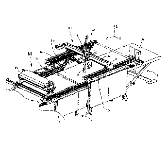
The apparatus comprises a frame 1 equipped with a top plane 1a on which
through known pneumatic systems the sheets of material to be weeded are fed
and
moved forward. Upstream of the plane there is arranged a feeder 2,
advantageously
having a lifting surface, with a motorised control, on which to position the
sheets with
dimensions that can vary from 200x300 mm to 1000x1400mm or also reels having
CA 02888131 2015-04-10
WO 2014/068450
PCT/1B2013/059576
- 5 -
corresponding size. The plane 2a of the feeder can comprise, along two
consecutive
sides, mechanical abutments that are suitable for allowing a reference of the
sides of
the sheet, the so-called "print register" sides. This, along with the control
of the height
of the plane, ensures that when a stack of sheets is arranged on the plane,
the sheet
on top, intended to be processed, is always positioned perfectly with respect
to the
work plane 1a of the frame 1.
A first part of the plane la, taking as a reference the advancement direction
of
the material indicated with the arrow X of figure 2, represents a fine weeding
station m,
that is a station of fine removal of small parts of weed, including those
parts that are
to generated by a plurality of weeding assisting cuts. Once the fine
weeding has been
carried out, the main body of the weed (through a rough weeding
station/process M
which will be described in greater detail hereafter) can be detached
completely and
effectively, without leaving residues, without tearing material or removing
undesired
parts.
A fine weeding device operates at the fine weeding station m (figure 2), with
a
gripper 3 that a portal 4 supports in a vertical arrangement, allowing the
gripper to
move along the three coordinates XYZ, in which the plane XY is the one
parallel to the
plane la and the axis Z is the direction along which the gripper 3 extends.
To such a purpose the portal 4 has a crosspiece 5 which can be displaced along
the advancement direction X and along which a carriage 6 moves, in accordance
with
the direction Y, and in turn supports the fine weeding gripper 3 through a
linear
actuation system along the direction Z. All such movements, just like those
that are not
specified otherwise, are controlled by motorizations implemented as obvious to
a
person skilled in the art. It is in any case worth noting how the movement
along Z of
the gripper 3 is advantageously carried out by means of a recirculating ball
system
driven by a direct brushless motor that ensures speed and precision with a
repeatability in the order of a hundredth of a millimetre.
The portal 4 also has a suction rod, which is not visible in the figures,
which
through a suction pad system feeds the sheet and arranges it so as to align
the front
left corner (imagining an observer which is standing looking towards the same
direction
as the advance movement direction) with a suitably pre-set reference. During
transport
CA 02888131 2015-04-10
WO 2014/068450
PCT/IB2013/059576
- 6 -
the sheet remains lifted in the front part that is gripped by the suction pads
but is
progressively made to adhere to the plane la in the remaining part towards the
tail.
The plane la is indeed connected to a vacuum pump system and the friction of
the
sheet created by the suction during movement ensures a perfect flatness
preventing
air bubbles or creases from forming on the sheet itself.
Once the sheet has been positioned on the suction work plane at the fine
weeding station m, the gripper 3 can carry out the fine removal of the various
(small)
weed parts, including those created by the plurality of weeding assisting
cuts,
according to the instructions from the control system, in turn processed on
the basis of
technical criteria that shall be further explained hereafter.
The gripper 3 is represented in particular in figures from 3 to 7c and
includes
from top to bottom (the reference is at the work position in alignment with
the axis Z) a
damper 7 (figure 4) and a pinching or gripping head 8 (figure 5) adapted to
come into
contact with the adhesive film and to remove it through pinching and lifting,
without of
course affecting the liner support underneath. The damper 7 has the function
of
ensuring that the head 8 exerts a pressure with constant intensity on the
material to be
worked, compensating for possible non-homogeneity in shape of the suction
plane,
and makes use of a pre-loaded spring 9 that elastically opposes the movement
of a
stem 10, through which the damper is connected to the head 8, the stem being
.. slidingly supported inside a base cylinder 11.
The head 8 moreover comprises an annular tool-holding flange 12 that can be
coaxially connected in a reversible manner, with a quick fit system that can
be driven
pneumatically, at the aforementioned stem 10 of the damper 7. Once the flange
is
removed, it can be supported in a suitable manner on a tool changing station
(replacement of jaws 16 and/or blocks 17 as detailed further on) through four
pins 13
projecting radially from the flange itself. A support disc 14 is connected to
the flange
12, again coaxially, on the opposite side of the stem 10, said support disc
being in turn
the support for a pneumatically driven self-centring chuck 15 equipped with
three radial
jaws 16 provided with respective pinching blocks 17 which represent the actual
manipulation element of the film/weed to be removed.
The jaws 16 are thus driven by the self-centring chuck 15 that, when
considered
CA 02888131 2015-04-10
WO 2014/068450
PCT/IB2013/059576
- 7 -
as such, has known mechanical characteristics. Through a base 16a of each jaw
16
the same jaws are linked with the chuck (figure 6); from the base 16a a strut
16b
projects, and at the free end of the strut 16b a relative pinching block 17 is
supported,
preferably obtained through electric discharge so as to ensure a perfect
mutual
adherence of the three blocks when the self-centring chuck, and therefore the
jaws,
take up a radially locked end stop position (closed position).
The block 17 is kept aligned by two pins 18 that prevent the sliding along the
axis
X and V. whereas the sliding along the axis Z is prevented by a plate 19 held
by a
screw 20.
Entering in greater detail as far as the shape of the pinching blocks 17 is
concerned, said shape being particularly meaningful for one aspect of the
invention,
each block has two front facets 17a that extend parallel with respect to the
axis Z,
separated by an edge 17b, forming an angle, measured on the plane XY, of 120 .
Those are indeed the faces that, by projecting frontally with respect to the
strut 16a of
the jaw 16, come into contact with one another causing the stop in the
aforementioned
closed position (shown in figure 3). The front facets 17a extend further in
the direction
Z at the lower side (the free one or pinching one) defining, in cooperation
with an
inclined wall 17c, a pyramid shaped projection at the top of which a contoured
prism-
like tip 17d forms the "finger" for gripping the material. Such a tip has an
elevation,
measured along the axis Z and with respect to the inclined wall 17c from which
it
branches off, in the order of some tenths of a millimetre, for example five,
enabling it to
sink into the adhesive plastic material without damaging the liner of silicone
release
paper underneath.
According to an embodiment shown in figures 8 and 9, the fine weeding device
comprises two or more grippers 3' that are supported in a carousel arrangement
that
allows for a greater work speed by hiding a discharge step of the weed pinched
by a
gripper, with respect to a fine weeding step carried out by another gripper.
In the
figures two grippers 3' can be noticed, mounted on a revolving support plate
41 that is
driven into rotation around the axis Z (that in this case is no longer the
central axis of a
single gripper, but the axis of the gripper system as a whole), by an actuator
42.
Moreover, the linear actuation system along Z is here indicated at 43. A shelf
44 can
CA 02888131 2015-04-10
WO 2014/068450
PCT/IB2013/059576
- 8 -
be also noted, supported by the crosspiece 5 and offering to the grippers 3',
in their
proximity, and in particular to the inactive gripper, the possibility to
unload the weed
previously pinched. Finally, a video-camera 45 and a lighting device 46 are
represented, these additional components advantageously assisting the control
of the
fine weeding process, ensuring a correct centering of the sheet to be
processed and a
consequent high precision on the pinching points previously determined by the
strategy
set by the control software. Besides, the reference marks on the sheet can be
focused
and the conformity of the material to a standard quality evaluated, so that
possible
defective pieces are traced and do not proceed further to the weeding process.
The operation of this embodiment can be easily appreciated in particular from
figure 9, that shows how in this case the support of the grippers 3' by the
plate 41 is
carried out with a further linear degree of freedom, according to directions
Z' parallel
with the axis Z. Such further degree of freedom is related with the weed
unload
function that indeed requires a reciprocating motion of lifting and lowering
the gripper
so as to leave the weed over the shelf. A elastic pusher 47 is secured with
the plate 41
and acts on the tail of the gripper 3' in the pinching position to calibrate
the force
applied in the pinching step. Two springs 48 are associated with respective
support
guide for the reciprocating motion of the single grippers 3', being urged
between the
same grippers and the plate 41 in order to compensate for the variations in
height due
to the elevation of the weed collection plane (defined by the shelf) and to
the
accumulation of removed weed.
Particular self-adhesive materials may require, for a correct unloading, the
provision of an air ejection through a nozzle (not shown) placed close to the
jaws of the
gripper and turned on as the weed is brought into contact with the unload
surface,
preventing that some parts may adhere to the surfaces of the gripper.
In operation, each fine weeding step thus occurs, in brief, with the
positioning of
the gripper on the appropriate coordinates XY, the jaws being in the open
configuration. The device then goes down along the axis Z closing the jaws in
a
synchronised manner in order to complete the run as they come into contact
with the
weed to be removed, which is thus gripped between the tips 17d that are
mutually
tightened. This action causes there to be a first detachment of the weed, the
removal
CA 02888131 2015-04-10
WO 2014/068450
PCT/1B2013/059576
- 9 -
of which is completed with a new lifting, not necessarily exactly vertical, in
some cases
and preferably preceded by a displacement along XY. By using the embodiment
with
the carousel arrangement, a new step as the one here just described is carried
out
getting rid of the waiting step necessary to the unload of the pinched/removed
material, because the rotation of the plate 1 makes a free and active gripper
immediately available while the other one unloads the material on the shelf
44,
possibly provided with an adhesive, weed collection belt as indicated by the
reference
numeral 44a. In the absence of a carousel system the single gripper can carry
out the
unloading or discharge over a sliding belt made from consumable plastic or
paper
material, with an obvious configuration which is not shown.
Once the fine weeding phase is over, the sheet proceeds over the plane la and
thus enters the already mentioned rough weeding station M in which a weed
seizing
head 21 of a rough weeding device operates (figures from 12 to 18),
cooperating in an
initial phase with a cutting unit 22 (figures 10 and 11). The rough weeding
device has
the configuration of a crosspiece arranged along the axis Y above the plane la
and it
is supported in a mobile manner along the axis X by a lateral guide system lc
of the
plane itself. An adjustment of the position along the axis Z can be also
provided,
through for example abutment screws to be actuated manually.
The seizing unit or head 21 comprises a front suction rod 23 that takes hold
of
the sheet and positions it above the cutting unit 22, embedded in the plane la
in an
inlet position of the rough weeding station M. In this phase, the suction
system of the
rough weeding head 21 carries out an opposing effect to the action of a blade
housed
inside a self-lubricating disk 27 that moves along the axis Y, controlled by a
pneumatic
piston, through a recirculating ball slide on the entire length of a linear
guide 24. The
liner of silicone release paper placed under the self-adhesive plastic
material is cut for
its entire width at a distance of around 2.5 cm from the front edge of the
sheet, so as
to define a flap or edge that can be easily folded upwards, with the
consequence and
the aim that shall soon become clear. The precision with which the blade sinks
into the
liner is ensured by a micrometer screw, whereas the stop abutment of the knife
is
ensured by a pneumatic piston 25 that brings the disk 27 in contact with the
supporting
plane of the sheet. The gap on the axis Z between the knife and the disk thus
defines
- 10 -
the depth of the cut.
Once the liner has been cut, the sheet still held by the suction rod 23 is
brought
inside the actual rough weeding station M, making the cutting line of the
liner coincide
= with a reference mark of a device for lifting the head flap of the liner.
Such a device is
schematically represented and indicated with reference numeral 36 in figures
from 19b
to 19j, and it consists substantially of a bar that can be lifted along the
axis Z through
linear pneumatic actuators that are not represented, between a lowered
position in
which it is concealingly integrated inside the plane la and a raised position
in which it
is capable of folding upwards by 900 the front flap or edge of the sheet,
defined by the
cutting means indicated above.
The lifting strip is preferably shaped with a staggered or comb-shaped edge
that
engages with a matching shape of the rough weeding plane, so as to lift the
flap or
edge at the end margin of the suction area, i.e. with the suction that is in
any case
active between the teeth of the staggering/comb and assists a lift precisely
by 90 of
the flap or edge.
A further component of the weed seizing head is a blower 28 that, on a plane
that is parallel and adjacent to the plane la, produces an ejection of
pressurised air
that is capable of covering the entire width (direction Y) and is directed
according to X,
in a direction that is in accordance with that along which the sheet advances
forward.
Advantageously, the blower 28, shown in particular in figures from 13 to 17,
takes the
shape of an elongated blade extending along the axis Y with a plurality of
adjacent and
independent sectors, for example ten, that are driven by respective solenoid
valves 29
in order to dispense air, through suitable channels 28b, during the movement
of the
sheet only where actually required.
The pressurised air comes out from a system of front slits 28a of the blower,
to
which a pair of rollers 30, 31 are associated, spaced along the direction X
and
arranged so that the blade is substantially tangent with respect to them. More
precisely, a rear roller 30 is made from silicone material, whereas a front
roller 31 is
preferably made from aluminium with a non-stick coating and is mobile towards
and
away from the rear roller 30. The rotation of such rollers is controlled by,
and is
synchronised with, the forward movement of the whole head, through a pinion
and rack
Date Recue/Date Received 2021-07-12
- 11 -
transmission (the pitch of the rack being in particular the same as the
diameter of the
two rollers).
In an upper area of the group, and therefore above the components described
above, there are a pull drum 33 with an incomplete development (that is,
without a
circular sector preferably having an angle that is equal or slightly lower
than 90 ) and
above the drum 33, a shaft 32 for collecting the weed in a reel (around a core
of
disposable cardboard), both motorized and arranged with their rotation axis
extending
along the axis Y. The motorisation of the roller and the shaft is mutually
independent,
with a torque limiter that can be set in order to ensure the correct tension
of the weed,
thus avoiding ripping or accumulation thereof. The winder 32 can moreover
translate
towards and away from the pull drum 33.
The incomplete pull roll, indeed thanks to its C-shaped section, defines a
radial
face 33a that cooperates with a clamp member 35 so as to be able to lock the
weed
and pull it.
Entering into greater detail as far as the work sequence of the rough weeding
process is concerned, and with particular reference to figures from 19a to
19j, the
blower blade 28 is positioned at the front edge of the sheet, indicated with
F. In figure
19a it can be noted also the folding flap Ft indeed generated frontally as a
result of the
half-cut previously mentioned (cutting line indicated with L). Initially, the
radial face 33a
of the C-shaped drum 33 is arranged perpendicular with the plane la, tangent
to the
back roller 30 and substantially aligned with the cutting line L. Also the
front margin of
the blower blade is positioned precisely in a way such as to coincide with the
cutting
line L. The clamp member 35 is open and the front roller 31 is in a forward
displaced
position (figures 19a and 19b).
As a result of the lifting of the folder 36, the folding flap Ft, including
both the
weed Fs and the liner Fl joined to one another, is folded upwards (figure
19c). At this
stage the front roller 31 retracts (figure 19d) and in cooperation with the
rear roller 30
seizes the material, in contact with the adhesive side and directs it upward,
whereas, at
the same time, the head retracts in direction X, in opposite fashion to the
advancement
motion of the sheet (figures 19d and 19e). While this occurs the weed Fs
starts
becoming detached from the liner of silicone release paper Fl, with the latter
kept in
Date Recue/Date Received 2021-07-12
- 12 -
contact with the plane 1a thanks to the suction exerted by it and to the jet
of the blower
28 which is responsible for the function, useful in some cases, of preventing
the lifting
of small parts belonging to the graphics and that must indeed stay placed on
the liner.
As visible from figure 19f, the weed Fs has been fed onto the radial face 33a
of
the pull drum 33 and the clamp member 35 can close to lock it. A rotation of
the drum
33 at this stage continues the removal of the weed Fs which is
circumferentially wound
around the roll, while in a coordinated manner, the head unit continues to
move
rearwards. The rotation also brings the weed to the shaft 32 bearing the
winding core.
In order to start collecting, the shaft 32 moves tangentially alongside the
drum 33
(figure 19h) so as to be, in turn, wrapped up by the same weed (figure 19i).
Once the
winding has been triggered, the shaft can lift up so as to allow it to freely
expand its
diameter (figure 19j).Of course, for each treated sheet, the aforementioned
sequence
is repeated and the reel of collected weed continues to grow. Once the
diameter of
such a reel has reached a set size, a sensor detects it, and stops the
apparatus so as
to allow the reel itself to be extracted and replaced with an empty cardboard
core.
Once made clear that the blower is not necessarily turned on in every
circumstances (being it possible that with some materials under treatment the
effectiveness of the result is not jeopardized by a lack of the pneumatic
action), in a
different embodiment, shown in figures from 20 to 23, the seizing head is
provided with
a movement of lifting/pulling the weed along the vertical axis Z, movement
that in
practice replaces the rotation of the rollers 30, 31 and the winding over the
pull drum
33, and by the same roll, in the first embodiment above described.
The seizing head in this case is indicated with the numeral 121, and is
arranged,
in structure and working process, in an analogous fashion with respect to the
first
embodiment as far as the initial steps are concerned (positioning the sheet
and "half
cut"). Accordingly, a further description of these steps is here omitted. The
figures
show a number of components that correspond to those of the previous
embodiment,
and are therefore indicated with a corresponding numeral in three digits (e.
the suction
bar 123).
The flap obtained with the "half cut", connected to the rest of the sheet only
via
the plastic film, is therefore the seizing point that allows for the start of
the detachment
Date Recue/Date Received 2021-07-12
CA 02888131 2015-04-10
WO 2014/068450
PCT/IB2013/059576
- 13 -
of the weed, to "free" the graphics. For the sake of a correct working, it is
important
that the processed sheet be positioned precisely on the suction plane, so that
the rear
cut results exactly on the folding/lifting line of the flap in the cutting
unit; to this purpose
the hold carried out by the suction system is kept active during the whole
process, to
have an appropriate reference for the displacement of the sheet from the half-
cut zone
to the rough weeding zone.
A blower blade is in this case indicated with the numeral 128 and, suitably
turned
on by electrovalves, can deliver air during the movement only when and where
positively required; the function of this air ejections is as mentioned
fundamentally to
oppose a possible lift of the graphic parts as the weed is removed. The
structure of the
blade has a certain flexibility to better accompany the sliding of the removed
material
and the interaction therewith even when it follows irregular geometric
contours due to
the particular graphic under process.
An idle roller 139 is associated to the blade 128 and is preferably lined with
a
silicon material in view of a better grip on the plastic film, In fact, the
task of this roller
is to lock the sliding of the sheet during the rough weeding process, ensuring
a safer
hold on the same sheet by the suction plane. Moreover, the compression of the
drum
on the self-adhesive material ensures that the graphic figures remain attached
to the
support liner and consequently prevents their lifting/removal as the weed is
detached.
The unit including the blade 128 and the roller 139 is mounted on a common
movable support 137, the position of which can be adjusted in the direction Z
thanks to
recirculating ball linear sliders 138 driven by pneumatic pistons. The result
thus
obtainable is to drive with a certain adjustable pressure the blade and the
roller onto
the material during the weeding steps, and to lift the blade in the inactive
steps, that is
when the unit must be moved without engagement with the sheet material.
The seizure of the weed occurs via plate members 131 seizing the lifted flap
and
moving upwards, carried by a slider 141, rising continuously in height along
the
direction Z, guided by a portal 140 and namely by linear guide means 140a
thereof.
The rising is coordinated with the movement of the same portal along the
direction X
(movement that occurs as in the previous embodiments, and followed by the
support
127 of the blade 128 and of the roller 139 that, contrary to the seizing means
131,
CA 02888131 2015-04-10
WO 2014/068450
PCT/IB2013/059576
- 14 -
remain adjacent with the working plane pressing the sheet). As a function of
the
different types of material under treatment, it is possible to set the
appropriate weed
removal strategy by synchronizing the two movements, so that a constant and
precise
pull of the material is ensured during the whole process as required by the
different
shapes of the graphics. Depending on the length and nature of the material, it
is
possible to leave a small portion of the sheet anchored for avoiding
fluttering during
the movement, thus assisting the subsequent phase of collection of the removed
weed.
In this case the collection of the removed weed is carried out by a collection
unit
to 132 (figure 23) that rises in height along with the slider 141 on the
guide portal, starting
from a minimum elevation that is the one the slider has to reach to start the
collection.
The collection unit 32 comprises two mutually opposed rotating plugs 132a, one
of
which is motorized, that form the shaft on which there is engaged the weed
reel
cardboard core. The increase in width that results from the accumulation of
weed on
the collection core is compensated thanks to a horizontal recovery movement
(along
X) by the plugs 132a. The winding movement is obtained thanks to the
motorization of
one of the two plugs, possibly with a motor with feedback control through an
external
encoder. Once the width of the reel of wound weed has reached a customizable
preset
size, an onboard sensor of the slider commands the stop of the apparatus and
the
replacement of the core, which is permitted thanks to a pneumatic unlock of
the non-
motorized plug 132a.
The various drives are carried out through motors and actuators having an
obvious nature to the skilled person and not described in detail.
The other above mentioned aspect of the invention will now be focused, i.e.
identifying and carrying out a plurality of weeding assisting cuts, before
performing the
weeding operations as described above.
In order to carry out such a working step, a specific procedure has been
developed that is capable of analysing, through processing means that are
integrated
with or associated to the actual apparatus, the graphical characteristics of
the material
being worked, and in particular of the weed, of intervening with preliminary
assisting
cuts, and of transmitting information/instructions to the control system of
the
CA 02888131 2015-04-10
WO 2014/068450
PCT/IB2013/059576
- 15 -
apparatus, in particular to the fine weeding device to guide the positioning
of the
gripper and the consequent pinching points of portions of weed defined by the
aforementioned cuts, with the aim of simplifying as much as possible the work
of the
apparatus, avoiding stress being exerted on the material in the weeding phase,
so as
to prevent it from being ripped.
Algorithms have moreover been implemented that can be easily adapted to any
type of geometry, and that are capable of determining assisting cuts in
accordance
with the lines of force dictated by the weeding direction so as to minimise
the stress
transmitted to the material being processed.
to The primary functions carried out in the process are thus those of:
- importing a graphic file into a processing unit;
- analysing the geometries present in such a graphic file;
- calculating the cuts to be added, and according to these, letting the user
decide
(or suggest) the most advantageous weeding direction;
- exporting a new modified vector file, to be used by cutting apparatuses.
Additional functions, that are not less important, are those that make it
possible
to export further information to be sent on to the central control unit of the
apparatus
(like for example a PLC), wherein such information will be exploited, as
already
mentioned, to drive the movement of the weeding devices, but also to
selectively
activate certain operations (like for example the selective actuation of the
air jets).
The files imported into the processor, representing images of the graphic
configuration of the sheet to be treated, are preferably vector file types,
such as for
example files having extension .dxf; however, other extensions are possible.
Hereafter there will be described in detail, as an example, i.e. according to
a
preferred embodiment, the various operational steps.
Once the file has been loaded, the data concerning the geometries therein are
imported and a dedicated algorithm controls the integrity of the data and
removes
double geometries or single dots that have been entered by mistake.
Based upon such data, the individual lines forming the graphic figures are
approximated, with polygonal structures (using for example the known SPLINE
interpolation). At this stage the file is displayed on a graphical interface.
CA 02888131 2015-04-10
WO 2014/068450
PCT/IB2013/059576
- 16 -
In this step the user can decide whether to exclude from the processing some
of
the figures that for functionality or for convenience were inserted in the
sheet, but that
do not require being cut by the plotter. It is also possible to exclude or
reinsert a certain
figure.
Once a portion of the sheet to be read has been selected, the algorithm
identifies
the entities that are inside the area and verifies whether these are part of a
repeating
block. Indeed, in the case in which there are repeating blocks on the sheet,
the
algorithm checks only one block, and the results are extended through analogy
to the
rest of the sheet. This makes it possible to substantially reduce computation
time and
unexpected malfunctioning of the system.
A recursive algorithm ' 38 (shown in figure 24) then verifies whether a
certain
entity is inside another one and in how many figures it is contained. The
algorithm 38
considers the entities contained in the repeating block (or all the elements
of the file),
initialises them at "LEVEL 0" and places them in descending order based on
their
surface area. Then, for each entity that is different from the first, it is
established
whether it is inside or outside the one with greater area and the function is
restarted in
a recursive manner on each of the two groups thus obtained. Only if the entity
is inside
another one, its level is increased and the entity containing it is stored.
Here, it is worth
underlining that all the flow charts represented in the figures representing
respective
algorithms or parts thereof are to be considered as incorporated in the
present
description. Insofar such charts are self-explanatory, they shall not be
described in
further detail.
Once the aforementioned algorithm 38 has been executed (when all the entities
have been examined and the "inner" and "external" groups are empty) an element
that
is not contained in any other group is defined as "LEVEL 0",, whereas all the
entities
contained in it as "LEVEL 1" and so on until an element is reached that does
not
contain any other (maximum level).
As a supplement to the previous algorithm, a second algorithm follows
completing the data in the case in which the repeating block of the previous
point has
been selected, and then a third algorithm identifies, for each entity, how
many and
which ones that are greater by a single level, are present inside it.
CA 02888131 2015-04-10
WO 2014/068450
PCT/1B2013/059576
- 17 -
The information thus obtained is fundamental in a fourth algorithm 39
(represented in figure 25), retrieving the parts of weed to be removed that
already
present inside the file (like for example inside of
an "A" or of an 0"). Such a fourth
algorithm (or PlotLevels algorithm) identifies as the internal weed part to be
removed
the area comprised between an entity having an odd level and all the entities
inside it
of a level that is immediately above, or an entity with an odd level that does
not contain
others inside it. Figure 26 highlights in a darker colour all the parts of
weed to be
removed present inside an example file.
At this point it is possible to determine and map cutting lines for dividing
the main
IC body of the weed, on the file, which in practice subdivide the areas of
the native weed
which after the first steps described above are excessively large (and could
thus create
problems during their removal). As shown in figure 27 the cutting function
obtains the
ends of the cutting segments that subdivide the area into different parts and
the points
of the scrap polygons that derive. The function also has the task of inserting
additional
cuts so as to divide the parts of weed derived by a difference of areas into
separate
polygons.
Concerning now the addition of the properly called assisting cuts,
substantially
two approaches have been developed: a first one consists of determining the so-
called
global cuts, or rather, those that are carried out, between each figure,
considering the
entities as associated; a second one consists of defining the local cuts or
edging cuts
determined according to the geometry of each single graphical figure.
As far as the definition of the global cuts is concerned, in this phase the
system
substantially manages the problem of the undercuts that are formed between
entities
close to one another along the weeding direction by scanning the sheet in its
entirety
so as to establish whether it is necessary to add cuts between one figure and
the next
or inside groups of figures. By undercuts it is hear meant the portions of the
sheet that,
during weeding, can be critical since they can rip the sheet or tear the
graphic design.
They usually correspond to portions with particular geometry (convexity,
changes of
direction, etc) but their criticality also depends upon the weed direction and
upon the
type of material with which the sheet is made.
The search for the points between which a global weeding cut is to be inserted
CA 02888131 2015-04-10
WO 2014/068450
PCT/IB2013/059576
- 18 -
includes an initial phase in which, for every figure, it is determined how
many and
which other figures are close or adjacent to it. The structure of the
algorithm that
implements such an initial step is represented in figure 28.
The block B1 analyses all the entities present in the file and, based upon the
result of the algorithm of figure 24 that identifies which figures are inside
others,
extracts only those that are on the outermost level ("LEVEL 0"). the
intermediate
blocks B2 and B3 calculate the barycentre of all the figures on that level and
the
relative distances between each of them. The fourth and last block of the
algorithm of
figure 28 uses the obtained data and builds a mapping at the outermost level
indicating
for each figure the number and which entities are close or adjacent in the
weeding
direction. In such a direction the algorithm moreover determines the free
space that is
indeed present for each entity.
In carrying out the aforementioned mapping each figure is associated to
another
according to the algorithm represented in figure 29.
The entity considered adjacent or closest is that which has the smallest space
along a certain direction, calculated as the difference between the
coordinates X or Y
(according to the weeding direction) of the mutually facing ends of the two
graphics.
The position of the entity is then identified, that is, it is determined
whether the
entity is completely opposed or partially opposed with respect to a close or
adjacent
entity: with the definition "completely opposed", in respect to a certain
direction, it is
meant that, when drawing two straight lines parallel with such a direction
passing by
the ends of the reference entity (points at minimum and maximum ordinate in
the
example of figure 30a), the opposed figure is intersected by both the straight
lines. If
the figure is not intersected by both the straight lines it is defined as
"partially
opposed".
The most suitable entities for the global weeding cuts are those that are
"totally
opposed"; on the other hand entities that are "partially opposed" are replaced
by those
having a barycentre at a minimum distance from that of the reference figure.
In the example in figure 30a (in which the letters "I" and "i" are
represented) it can
be seen how the opposed and closest entity to the letter "I" along the left-
right direction
is the dot of the "i" whereas the one with the barycentre closest is the stem
of the "i".
CA 02888131 2015-04-10
WO 2014/068450
PCT/IB2013/059576
- 19 -
The algorithm initially reads the dot of the "i" and establishes that it is
not completely
opposed since one of the two straight lines highlighted in bold does not
intersect the
entity. Therefore the figure coupled with the letter "I" for carrying out the
global
weeding cuts is the stem of the "i", since it is the one with the closest
barycentre.
In the subsequent example (visible in figure 30b) it is possible to see how
the
figure to be considered the closest to the letter "n" at the top, along the
top-bottom
direction (according to the arrow F), is not the letter "n" below (which in
any case has
the closest barycentre) but rather the rectangle 39 placed between the two
words that,
in addition to being the closest figure, is also intersected by both the
straight lines.
Next, in figure 30c an example is shown with a weeding direction from left to
right
(according to the arrow F). Considering the letter "0" on the left, inside the
two
horizontal half lines drawn starting from the points at minimum y and maximum
y, the
closest entity is the letter "I" which has the minimum distance both with its
barycentre
and with its minimum x.
Once all the couplings have been carried out there is the problem of dealing
with
some particular cases that occur, namely, if many entities identify one same
entity as
the closest one (like in figure 30b in which all the letters of the upper word
identify the
central rectangle), or if an entity has other entities with which to connect
in addition to
the closest, or even the case in which there are sets of three entities with
one having
dimensions that are much smaller with respect to the other two. Each of these
particular cases is dealt with by dedicated sub-algorithms, and in this way
the general
mapping is completed indicating for each entity how many and which figures are
to be
considered coupled for the global weeding cuts to be carried out.
After this initial phase a fifth algorithm, based upon the previous mapping
and the
weeding direction, decides the points in which it is advantageous to insert a
cut.
Indeed, such an algorithm, for each couple or group of entities, identifies
the points
between which to carry out an additional cut (possibly adjusted so as to not
interfere
with the previous graphical element). Between two additional cuts and the two
(or
more) entities that are affected by the cutting, a new derived polygon is thus
identified
as schematically shown in figure 31.
For each figure on the outermost level, sub-algorithms receive as an input the
CA 02888131 2015-04-10
WO 2014/068450
PCT/1B2013/059576
- 20 -
points of the entities involved, and return as an output the ends of the
segments
representing the optimal cuts; the algorithm thus selects the initial points
in proximity to
the ends of the figures (in the example in figure 31 the points are P1, P2',
P3, P4). In
the case in which there is an intersection between the potential cut and one
of the two
entities, a new point is identified (in this case P2) that generates a cutting
line that
does not intersect the graphical element, i.e. a cutting line that is tangent
with the edge
of the figure.
Further sub-algorithms receive in input the coordinates of the identified cuts
(P1,
P2, P3 and P4) and the coordinates of the involved entities, and extract the
points of
the scrap polygon that derives, indicated in figure 31 with 40.
As far as the local cuts are now concerned, it should be considered that for
very
delicate materials the problem of accidental tearing occurs also for figures
that have
high discontinuity characteristics, in terms of angles between the weeding
direction
and the last side of the figure encountered going along such a direction. In
order to
solve the problem it is indeed provided to insert local additional cuts to
edge the figures
more regularly, so as to reduce the undercut angle and avoid tearing. All the
figures
that were not previously joined to other ones with the global cuts are thus
analysed and
the coordinates of the points from which to make the cuts start are searched
so that
these are substantially tangent to the figure.
The algorithm that carries out the local cuts on a single figure is
represented in
figure 32. The algorithm identifies a polygon that follows the convexity of
the figure
under consideration (indicated in the algorithm as "Convex Hull",
corresponding to the
known mathematical entity of convex envelope); the intersection of this
polygon with
the figure provides for the concavities, which are the most critical parts of
the geometry
during removal.
Once the concavities have been identified there is determined, on the basis of
the weeding direction, whether they can cause the ripping of the graphical
element in
particular for their being undercuts, and therefore it is necessary to proceed
with a
relative closure or edging cut.
One of the parameters for evaluating whether a concavity is an undercut or not
is
that of determining the relative position with respect to the initial figure.
CA 02888131 2015-04-10
PCT/IB2013/059576
WO 2014/068450
-21 -
With reference to figure 33a, it can be understood that if the rough weeding
direction is from left to right (according to the arrow F), the area
identified with Cl will
not cause problems at the moment of removal, since proceeding in such a
direction the
geometry of the figure follows the weeding direction; substantially no
stresses are
generated on the material, since they extend in the opposite or crosswise
direction with
respect to the direction imposed by the weeding operation, therefore there is
no risk of
tearing.
On the other hand, if the weeding direction is from right to left (according
to the
arrow in figure 33b) the area C2 undergoes a stress that is opposite to the
weeding
direction and causes the material to rip.
In order to identify the relative position of one part with respect to the
initial
figure, i.e. to determine in which position a certain concavity is and thus
evaluate its
risk of ripping during weeding, four points of the figure itself must be
identified that
correspond to the top left point, top right point, bottom left point and
bottom right point,
respectively; in figure 33c these points are indicated with:
¨UL (Up, Left)
¨UR (Up, Right)
¨BL (Bottom, Left)
¨BR (Bottom, Right)
Ordering the vector of the points clockwise, and ensuring that the BL point is
in
the first position, it is possible to establish the position of the concavity.
There remains now necessary to determine the geometry of the concavity that
together with the relative position and the weed direction are the three
parameters that
make it possible to determine whether or not a certain area can be considered
an
undercut.
A sub-algorithm is thus implemented that classifies the concavities as regular
or
irregular on the basis of the position of key points, of the weeding direction
and of the
relative position that the object occupies with respect to the initial figure.
A practical example to be considered is given by the graph of figure 34a and
in
particular the area indicated in grey. The points P representative of such an
area, i.e.
= those in which a change of direction on the axis X can be noticed, are
ordered in the
CA 02888131 2015-04-10
WO 2014/068450 PCT/1B2013/059576
- 22 -
direction indicated by the arrows G in black. At this point the following
matrix is
= constructed:
1 1 1
1 00
The presence of 0 on the second row indicates that the arrangement of the
representative points is not ordered, this meaning that when proceeding in the
direction of the arrows from the point marked with P', the points encountered
do not
always follow a decreasing Y coordinate ratio. This imposes a further check on
the
coordinate X, that is on the first row. If the first row comprises all 1
symbols, it means
that the points are arranged with ascending X and therefore when proceeding in
the
weeding direction F, stresses counteracting the movement will not be
encountered.
The investigated area is not therefore an undercut.
When considering now the area indicated with D in figure 34b, the points of
which were ordered in the direction indicated with the arrow G, three
representative
points P are identified that lead to the construction of the matrix shown
below:.
01
01
Having 0 symbols on the second row indicates that the arrangement of the
representative points is not ordered on the axis Y. Continuing the search on
the first
row, the presence of 0 indicates that the points are not ordered for the axis
X either.
Such an area is therefore an undercut.
With reference again to the algorithm of figure 32, if the area under
consideration
is an undercut a local cut is carried out. The presence of a possible global
weeding cut
is this verified. There is furthermore a further check that verifies that the
cut made
does not go over another entity and in order to increase the level of
reliability of the
system it is then foreseen for there to be the possibility for the user to
insert or remove
the cuts manually.
The process ends with the determination of the pinching points of the fine
weeding gripper 3 selected on the basis of the position of the scrap portions
to be
weeded. The scrapes to be removed consist not only of weed parts natively
existing
inside the graphics, but also of all the weed parts generated as a result of
the
CA 02888131 2015-04-10
WO 2014/068450
PCT/1B2013/059576
- 23 -
additional cuts. Based on the size and the shape of the parts to be removed,
it will not
be always possible to remove the material by simply pinching it at any point
and
moving the gripper vertically.
Entering into further details in connection with the aspect of deciding the
pinching
point of a fine weed part and the control of the movement of the pinching
gripper, it
should be noted that the algorithms searching for the additional cut patterns
give as an
output/result the coordinates of the extremities of the same cuts, and of the
vertices of
the resulting scrap polygons. With the aim of sparing the control system of
the
apparatus the execution of a significant number of operations (so that the
working
speed is improved), the choice of the pinching points can be directly carried
out by the
software on the processor that assists the apparatus, while the apparatus
control
system is left with the task of controlling the movement along the Cartesian
axes and
has only to read the above mentioned points in a interchange file (e.g. having
a .iso
format)
Firstly, a pinching point needs be chosen that permits a complete removal of
the
scrap portion with the subsequent movement of the gripper. Said point must be
adapted to let the gripper tighten without interfering with other parts of the
adhesive
film that must indeed not be touched. In substance, one has to identify a
circle having
a radius equal to opening span of the gripper and that is completely within
the figure to
be removed. The determination of each most suitable pinching point can be
implemented e.g. by the algorithm shown in figure 35; this identifies a circle
with radius
equal to the radius of action of the gripping head 8 that must be totally
inside a scrap
portion.
In the case in which the scrap is generated by one or more local cuts, the
search
of the pinching point of the gripping head 8 occurs firstly along the cuts
themselves so
that the circumference is tangent to the cut segment and inside the scrap. If
it is not
possible to find a circle that is totally inside the scrap surface it is
necessary to
decrease the working range (radial displacement) of the jaws 16 of the head,
or rather,
replace the pinching blocks 17 adapting their dimensions, and repeat the
algorithm.
, On the basis of the size of the scrap and of the pinching point, the type of
movement that the gripper 3 has to carry out in order to achieve the weeding
is
CA 02888131 2015-04-10
PCT/IB2013/059576
WO 2014/068450
- 24 -
implemented. In figure 36 it is possible to observe the result following the
execution of
the algorithm: 42 indicates the scrap portions, PP indicates the pinching
points and PD
indicates the destination points of the movement of the gripping head.
In an alternative embodiment, instead of differentiating the identification of
the
pinching point depending on the fact that the scrap region is or not generated
by
supplementary assisting cuts, it is at first verified if the scrap figure
under examination
has some concavities or is simply convex. In fact, if it is convex and its
surface area is
comparable with the gripping surface of the gripper (for instance an area not
greater
than 500% of the pinching surface of the gripper), then the gripper is placed
so as to
pinch at the barycenter of the same figure.
If the previous condition is not satisfied, then a polygon is evaluated that
circumscribes the figure. The polygon is divided into four zones (Top-Left,
Top-Right,
Bottom-Left, Bottom-Right). For each of these zones, there is evaluated the
ratio of
surface area that is occupied by the scrap, choosing the area with the highest
occupation ratio, or in case of equal ratios the zone that it is first met,
starting from the
top left and proceeding clockwise.
Once chosen the area, the best point to pinch the figure is individuated, as
above, along a cut/size of the figure.
As far as the exit trajectory of the gripper is concerned (once the scrap has
been
pinched), in case of barycentric pinch the same gripper can detach the scrap
figure by
simply accomplishing a vertical lifting motion, or in any case a motion that
has a certain
slant (e.g. 45 ) that determines a component along Z. In case instead of a
perimetrical
pinch, a movement over the plane XY will be advantageously carried out,
directed
towards the barycenter, for an amount that is optimized depending on the
material and
the shape; the movement can also continue beyond the barycenter until the
perimeter
of the figure is reached and passed. Finally, the operation is completed with
a lifting of
the head.
Returning to the step in which the supplementary assisting cuts are made, an
even further aspect is worth a remark. Not necessarily such cuts are directed
to define
some weed scrap structures with a closed polygonal boundary to be removed in
the
fine weeding step. Said cuts can also be single segments that always start
from an
CA 02888131 2015-04-10
WO 2014/068450
PCT/1B2013/059576
- 25 -
edge of a graphic element, but end "blind", that is they stop in the main
native weed
without joining other cuts or edges. This kind of cuts are drawn in particular
in
correspondence with sharp corners formed by the graphic elements with the
vertex
that points opposite to the rough weeding direction, running on the main weed
starting
from said vertex in order to prevent that when the weed is detached (indeed
during the
rough weeding stage), an undesired detachment of the graphic may also follow.
The present invention provides therefore an apparatus and a method capable of
making the weeding process effectively automatic(not necessarily in the time
order
rough after fine as in the example, but possibly even in the contrary order),
remarkably
to reducing the production times and significantly improving the productive
results as far
as costs and reliability are concerned.
The present invention has been here described with reference to preferred
embodiments. It should be understood that that there may be other embodiments
= within the same inventive concept, as defined by the scope of protection
of the
following claims.