Note: Descriptions are shown in the official language in which they were submitted.
CA 02888179 2015-04-14
WO 2014/072677
PCT/GB2013/052502
SINGLE USE, FOLDABLE DISPENSER FOR
AN ADHESIVE LAVATORY TREATMENT COMPOSITION
The present invention relates to a single use, foldable dispenser for an
adhesive
laboratory treatment composition.
The prior art has suggested certain dispensers which may be used to dispense a
dose or portion of an adhesive product onto a surface.
In US 2012/0037301 Al is disclosed an applicator for a self-adhesive material.
The applicator includes an outer surface, and an inner surface which defines a
void
adapted to receive a self-adhesive material. The applicator may be used to
deposit the
self-adhesive material onto a surface.
WO 2012/017276 (PCT/1B2011/001160) discloses sanitary cleaning agents which
are covered by a water soluble film.
EP 2141221 discloses an applicator device for an adhesive detergent product,
whereby the device may be used to apply the adhesive detergent products to a
vertical
wall, such as the sidewall of a toilet bowl.
While the prior art suggests certain embodiments of applicators, useful with
specific adhesive material compositions, these devices are not without their
shortcomings. For example, the device disclosed in US 2012/0037301 Al is
relatively
bulky, and rigid, requiring increased amount of storage volume prior to its
use.
Furthermore, the amount of materials, presumably thermoplastic polymeric
materials
which are used to form the applicator may be considered excessive for use in a
single-use
type device. The applicator device disclosed in EP 2141221 is effective, but
requires that
the fingers of a human user utilizing the applicator device to deliver a
quantity of the
adhesive detergent product to the interior sidewall of a toilet bowl come in
near proximity
to, and may come into contact with this interior sidewall. Such is a very
unfavorable
manner of applying such a product from a consumer standpoint, who desirably
avoids
81771844
physical contact with the interior sidewall of a toilet bowl. It is to these,
as well as further
shortcomings in the art to which the present invention is directed.
In a broad aspect the present invention provides a single use, foldable
dispenser for an
adhesive lavatory treatment composition.
FIG. 1 depicts an embodiment of a single use, foldable dispenser of the
invention.
FIG. 2 depicts the embodiment of FIG. 1 in an unfolded, generally planar
configuration.
FIG. 3 depicts a view of the embodiment of FIG. 1.
FIG. 4 depicts a further view of the embodiment of FIG. 1, and further
illustrates a cover
film.
FIG. 5 depicts a further embodiment of a dispensing device according to the
present
invention.
FIG. 6 depicts a further view of the embodiment of FIG. 5.
FIG. 7 depicts a yet further embodiment of a dispensing device according to
the present
invention.
FIG. 8 depicts a further view of the embodiment of FIG. 7.
FIG. 9 depicts a further view of the embodiment of FIG. 7.
FIG. 10 depicts a further view of the embodiment of FIG. 7.
FIG. 11 depicts a configuration of the dispensing device of FIGS. 7-10
immediately after a
quantity of an adhesive treatment composition has been adhered to the sidewall
"SW" of the
lavatory appliance.
FIG. 12 depicts a still further embodiment of a dispensing device according to
the present
invention.
FIG. 13 depicts a further view of the embodiment of FIG. 12 in an alternate
configuration.
FIG. 14 depicts a still further view of the embodiment of FIG. 12 in an
alternate
configuration.
FIG. 15 depicts another alternative embodiment of a dispensing device
according to the
present invention.
FIG. 16 depicts a further view of the embodiment according to FIG. 15.
FIG. 17 depicts a further view of the embodiment according to FIG. 15 in a
folded
configuration.
FIG. 18 depicts an array of dispensing devices.
FIG. 19 depicts a further array of dispensing devices.
2
CA 2888179 2019-10-29
81771844
In a first preferred embodiment, the single use, foldable dispenser includes a
generally
centrally located base which includes a cavity, from which base extend
outwardly and in opposite
directions one or more foldable arms which may be hinged about the base
portion such that in an
initial configuration, one or both of the arms are generally coplanar with a
flat surface of the base
and/or the opening of the cavity, and in a further configuration both of the
arms are folded
rearwardly of the base and cavity so that at least a portion of each of the
arms extends above the
cavity. In particular preferred embodiments, two rearwardly folded arms
contact each other, and
preferably come into an interfacial laminar contact, or optionally into an
interlocking contact by
virtue of one or more interlocking means which may be provided with the
dispenser, and/or which
are incorporated into the construction of one or both of the arms.
In accordance with a second embodiment, optionally but preferably, the single
use,
foldable dispenser additionally includes as a release means, a release film
which extends into the
cavity, and in which at least part of the release film may be temporarily, or
permanently affixed to
a part of the dispenser.
In accordance with a third embodiment, optionally but preferably, the single
use, foldable
dispenser additionally includes as a release means, a release material which
extends into or is
contained within the cavity, and which forms a barrier between the contents of
the cavity of the
dispenser and the dispenser itself.
In a fourth preferred embodiment, optionally but preferably the single use,
foldable
dispenser additionally includes a cover film or other cover means which spans
across the open end
of the cavity and may be removed therefrom prior to dispensing of any material
contained within
the cavity.
In a fifth preferred embodiment of the single use, foldable dispenser,
optionally but
preferably, at least one, but preferably both of the arms are also
sufficiently flexible in a forward
direction such that when folded forwardly at least a part of at least one of
the arms may be used to
form a cover means over the open end of the cavity of the base
2a
CA 2888179 2019-10-29
CA 02888179 2015-04-14
WO 2014/072677
PCT/GB2013/052502
portion, and which arm may be removed prior to dispensing of any material
contained
within the cavity.
According to a sixth preferred embodiment, there is provided a single use,
foldable dispenser, which includes a base portion which comprises a cavity,
and a single
foldable arm which may be hinged around the base. Preferably, in an initial
configuration
the arm is folded forwardly such that at least part of the arm is used to form
a cover
means over the open end of the cavity of the base portion, and in a further
configuration,
the arm is folded away from the open end of the cavity of the base portion,
preferably
such that the arm is generally coplanar with the base portion.
In a further embodiment there is provided a single use, foldable dispenser
according to any of the preceding embodiments disclosed herein, or otherwise
described
in the specification, which contains a quantity of an adhesive lavatory
treatment
composition or an adhesive detergent product which is preferably a viscous
paste or gel
product.
In a still further embodiment there is provided a method of making a single
use,
foldable dispenser adapted to be used for storing, and dispensing a quantity
of an
adhesive lavatory treatment composition.
In a yet further embodiment of the invention there is provided a method of
applying an adhesive lavatory treatment composition to a surface from a single
use,
foldable dispenser according to any of the preceding embodiments disclosed
herein, or
otherwise described in the specification.
In a further embodiment there is provided as a vendible product a single use,
foldable dispenser containing a quantity of an adhesive lavatory treatment
composition.
These and further embodiments of the invention will be more apparent from the
following specification and drawings which illustrate certain embodiments of
the
invention.
The dispensers of the invention may be used to contain and to delivery a
quantity
of an adhesive treatment composition to a surface. In preferred embodiments
the
adhesive treatment composition is an adhesive lavatory treatment composition.
Examples of adhesive treatment compositions which may be contained and
delivered to a
surface from the dispensers of the invention include compositions which are
known to the
3
CA 02888179 2015-04-14
WO 2014/072677
PCT/GB2013/052502
art. Such include (but are not limited to) those disclosed in the following
published
patent documents: EP 0864637; EP 108699; EP 1086204; EP 1318191; AU
2001285865; EP 1817399; EP 1953215; EP 2250245; EP 2275524; DE 1020080192; US
2011/0002871 Al; US 2011/0142784 Al; US 2011/0142785 Al; EP 2121893; EP
2363457; EP 2167627; EP 2387606; EP 2419349; EP 2445806; US 7919447; US
2009/0215909, US 2009/0325839; US 2010/0325839; US 2010/0216685; US
2011/0017406; US 2011/0033224; US 2012/0108490; US 2009/0215909; EP 2254980;
EP 2387605; US 8143205; US 8143206; US 2012/0232165; US 2012/0232170; EP
1978080; EP 2141221; DE 19910788; US 6521578; EP 2082020; US 2010/130400; US
2010/162474; US 8076.278; US 2010/130399; US 6336977; US 2008/057020; US
2008/058239; US 2008/058240; US 2008/058241; US 2008/099041; EP 2316914; EP
1625195; EP 2336290; EP 2159276; EP 2328997; WO 2012/017276; US 2012/0037301;
WO 201.2/013490; EP 1418225; WO 2012/052379; EP 2473421; WO 2012/01.7277; WO
2012/017278; EP 228.1756 and US 2012/0178824.
In certain particularly preferred embodiments the dispensers of the invention
may
be used to contain and to delivery a quantity of a self-adhesive lavatory
treatment
composition which comprises (or, consists essentially of, or consists of):
an adhesion promoter based on a fatty alcohol polyglycol ether as may be
represented by the following structural formula (I):
R-0-[C H2-C H2-03 H
(I)
within which, R is an C2-C24 aliphatic mono- or poly- alkene moiety, and n has
a value
of from 1 to 30;
an organic solvent constituent, which is liquid at room temperature (20 C);
a surfactant constituent;
water;
optionally a co-adhesion promoter constituent, preferably based on one or more
oxyalkylenated compounds;
and, further optionally one or more further optional constituents which may
impart a further aesthetic or technical benefit to the said self-adhesive
lavatory treatment
compositions;
4
CA 02888179 2015-04-14
WO 2014/072677
PCT/GB2013/052502
wherein in use, the said self-adhesive lavatory treatment compositions may be
applied and adhered to a dry or wetted ceramic surface, especially the
interior sidewall in
a toilet bowl or other lavatory appliance, and wherein the said self-adhesive
lavatory
treatment compositions is retained adhered to the said surface following a
plurality of
flushes of water impinging upon the adhered self-adhesive lavatory treatment
compositions.
In said self-adhesive lavatory treatment composition the adhesion promoter is
one
or more fatty alcohol polyglycol ether, as may be represented by the following
structural
formula (I):
R¨O-P H2-C H2-03 H
n (I)
within which:
R is an C12-C24 aliphatic (poly)alkane moiety, and
n has a value of from 1 to 30 , but preferably n has a value of from 8 to 20,
and
most preferably has a value of from 10 to 20, inclusive.
Preferably R is a residue of a Ci2 ¨ C24 fatty alcohol having at least one
unsaturated bond, viz., monounsaturation, but the residue of a Cu ¨ C24 fatty
alcohol is
preferably monounsaturated. While the residue of a C12 ¨ C24 fatty alcohol may
have
one or more branches, it is preferably linear. Mixtures or blends of two or
more such
fatty alcohol glycol ethers may also be used.
In preferred embodiments the adhesion promoter based on a fatty alcohol glycol
ether, conforms to the foregoing structural formula and comprises one or more
unsaturations within the midsection of the Cu ¨ C24 fatty alcohol, e.g,
wherein the
location of the at least one unsaturation (preferably a single unsaturation is
present) is
within the interior portion of the carbon molecules as measured from the
midpoint of the
C12-C24 aliphatic (poly)alkane moiety and extending outwardly therefrom from
both sides
from the central carbon(s) which is/are equidistant from the two most distal
carbon atoms
of the longest carbon chain in the Cu-C24 aliphatic (poly)alkane moiety. Thus
for
example, if the R is a linear C14 fatty alcohol, which is an even numbered
fatty alcohol,
then the central carbon(s) are the C7 and C8 carbons which are also at the
midpoint as
measured from the distal, Ci and Ci4 carbons of theis fatty alcohol. Where,
for example
5
CA 02888179 2015-04-14
WO 2014/072677
PCT/GB2013/052502
R is a odd numbered fatty alcohol, e.g. where R is a C15 fatty alcohol, then
the central
carbon is the C8 alcohol which is at the midpoint, as being equidistant from
both the Ci
and Ci5 carbons of the fatty alcohol. The midpoint carbon(s) may also be
identified by
the following equation:
N/2 = midpoint carbon(s)
wherein:
N is the number of carbon atoms in the longest carbon chain in the C12-C24
aliphatic (poly)alkane moiety, corresponding to R in the foregoing structural
formula.
Wherein "N" is an even number then the foregoing equation will yield a value
with no
decimal remainder (e.g., for a C14 aliphatic (poly)alkane moiety, N = 14, and
thus N/2 =
7), then the midpoint carbons are the N/2 carbon, and the adjacent (N/2)+1
carbon. Such
corresponds to the 7th and 8th carbons in the C14 aliphatic (poly)alkane
moiety. Wherein
"N" is an odd number then the foregoing equation will yield a value with a
"0.5" decimal
remainder, (e.g., for a C15 aliphatic (poly)alkane moiety, N = 15, and thus
N/2 = 7.5),
then the midpoint carbons is (N/2)+0.5 carbon. Such corresponds to the 8th
carbon atom
in the C15 aliphatic (poly)alkane moiety.
Preferably the one or more unsaturations present with the C12-C24. aliphatic
(poly)alkane moiety are between adjacent carbon atoms which are between the (N-
N+2)
carbon atoms and the (N-2) carbon atoms, and in order of increasing preference
are:
between the (N-N+4) carbon atoms and the (N-4) carbon atoms, and between the
(N-
N+5) carbon atoms and the (N-5) carbon atoms of the Cu-C24 aliphatic
(poly)alkane
moiety.
Preferably the one or more unsaturations present with the C12-C24 aliphatic
(poly)alkane moiety are between adjacent carbons which are within four carbons
adjacent
to one or both of the midpoint carbon(s), preferably are within three carbons
adjacent to
the one or both of the midpoint carbon(s), and especially preferably is/are
between
adjacent carbon atoms at least one of which is the midpoint carbon(s) in the
longest
carbon chain in the Cu-C24 aliphatic (poly)alkane moiety.
Particularly preferred fatty alcohol glycol ethers of the foregoing structural
formula (I) include those which have two or less unsaturations in the R
residue, and
particularly preferred are those which have a single unsaturation in the R
residue.
6
CA 02888179 2015-04-14
WO 2014/072677
PCT/GB2013/052502
In certain preferred embodiments the R residue of the fatty alcohol polyglycol
ether of the foregoing structural formula (I) is derived from a
monounsaturated fatty
alcohol which may be represented by the following formula (II):
CH3(CH2)õCI-CH(CH2)y¨CH2OH
(II)
in which each of x and y are integers which have a value in the range of 6-32,
preferably
in the range of 8-18, and further preferably the value of x:y are within the
respective
ratios of from 0.5:1 ¨ 1:0.5 preferably 0.75:1 ¨ 1:0.75, and especially
preferably about
1:1.
Preferred fatty alcohol glycol ethers of the foregoing structural formula (I)
include
those which are presently commercially available in the Genapol "0" series
of
nonionic surfactants, and in which the fatty alcohol glycol ethers include a
residue baed
on an oleyl alcohol which has a structure: CH3(CH2)7-CH=CH-(CH2)8-0H, and
contains
a single monounsaturation at or near the midpoint from the terminal ends of
the fatty
alcohol. Further preferred fatty alcohol glycol ethers of the foregoing
structural formula
(I) include those which are presently commercially available in the Genapol
"U" series
of nonionic surfactants.
Advantageously the adhesion promoter based on a fatty alcohol polyglycol ether
is present in the compositions in amount of from about 10%wt. to about 50%wt.,
preferably from about 20%wt. to about 45 /owt. based on the total weight of
the self-
adhesive lavatory treatment compositions of which they form a part.
In the particularly preferred self-adhesive lavatory treatment compositions,
the
organic solvent constituent, which is liquid at room temperature (20 C),
comprises one or
more organic solvents as the organic solvent constituent, but in preferred
embodiments is
a single organic solvent. By way of non-limiting example exemplary useful
organic
solvents which are liquid at room temperature (20 C) and which may be included
in the
inventive compositions are those which are at least partially water-miscible
such as
alcohols (e.g., low molecular weight alcohols, such as, for example, ethanol,
propanol,
isopropanol, and the like), glycols (such as, for example, ethylene glycol,
propylene glycol,
hexylene glycol, and the like), water-miscible ethers (e.g. diethylene glycol
diethylether,
diethylene glycol dimethylether, propylene glycol dimethylether), water-
miscible glycol
ether (e.g. propylene glycol monomethylether, propylene glycol mono
ethylether, propylene
7
CA 02888179 2015-04-14
WO 2014/072677
PCT/GB2013/052502
glycol monopropylether, propylene glycol monobutylether, ethylene glycol
monobutylether,
dipropylene glycol monomethylether, diethyleneglycol monobutylether), lower
esters of
monoalkylethers of ethylene glycol or propylene glycol (e.g. propylene glycol
monomethyl
ether acetate), and mixtures thereof. Glycol ethers having the general
structure Ra-Rb-OH,
wherein Ra is an alkoxy of I to 20 carbon atoms, or aryloxy of at least 6
carbon atoms,
and Rb is an ether condensate of propylene glycol and/or ethylene glycol
having from one
to ten glycol monomer units. Polyhydroxy organic solvents, viz, those having
two or
more ¨OH moieties are in certain cases, preferred for use.
The organic solvent may also include one or more further liquids such as
glycerine and paraffin oil, as well as petroleum distillates and/or petroleum
products,
paraffinic oils usually based on n-alkanes, naphthenic oils usually based on
cycloalkanes,
aromatic oils such as those based on aromatic hydrocarbons, mineral oil, as
well as
technical grade mixtures of hydrocarbons may be used as or in the organic
solvent.
Examples of the latter include paraffinic hydrocarbons including both linear
and
branched paraffinic hydrocarbons; the former are commercially available as
NORPAR
solvents (ex. ExxonMobil Corp.) while the latter are available as ISOPAR
solvents (ex.
ExxonMobil Corp.) Mixtures of branched hydrocarbons especially as isoparaffins
form
are also contemplated to be useful.
In certain preferred embodiments the organic solvent constituent necessarily
includes at least one glycol or glycol ether, and further includes one or both
of glycerine
and/or mineral oil. When such at least one glycol or glycol ether is present
in
conjunction with one or both of glycerine and/or mineral oil, preferably the
mass of the at
least one glycol or glycol ether is at least about three times, preferably at
least about four
times that of the total mass of the glycerine and/or a mineral oil present.
In certain preferred embodiments the organic solvent constituent consists
essentially of, yet more preferably consists of, at least one polyhydroxy
organic solvents,
e.g, a glycol or glycol ether, and further includes one or both of glycerine
and/or mineral
oil.
In further, certain preferred embodiments the organic solvent constituent
consists
essentially of, yet more preferably consists of, at least one glycol or glycol
ether, and
mineral oil.
8
CA 02888179 2015-04-14
WO 2014/072677
PCT/GB2013/052502
In further, certain preferred embodiments the organic solvent constituent
consists
essentially of, yet more preferably consists of, at least one glycol or glycol
ether, and both
glycerine and mineral oil.
The organic solvent constituent comprises 1 ¨ 25%wt. of the inventive
compositions. Preferably, in order of increasing preference the organic
solvent
constituent is present in an amount of at least about 1%, 1.5, 2%, 2.5%, 3%
wt. of the
inventive composition of which they form a part. Preferably, in order of
increasing
preference the organic solvent constituent comprises not more than about 25%,
20%,
18%, 17%, 16%, 15%, 14%, 13%, 12%, 11%, 10%, 9.5%, 9%, 8.5%, 8%, 7.7%, 7%,
6.5%, 6%, 5.5% and 5% wt. of the inventive composition of which they form a
part.
Particularly preferred amounts of the organic solvent constituent are recited
in one or
more of the Examples, with preferred ranges of the organic solvent constituent
also
disclosed in the Examples.
In certain preferred embodiments:
(a) the ratio (in %wt.) of polyhydroxy organic solvent:other solvents of the
organic solvent constituent is in the range of about 4-12:1, preferably about
4.5-10:1, and
especially preferably 4.5-8.5:1; and/or,
(b) the ratio (in %wt.) of polyhydroxy organic solvent: mineral oil is in the
range
of about 5-20:1, more preferably about 7:18:1; and/or,
(c) the ratios (in %wt.) of water: organic solvent constituent is in the range
of
about 5-20:1, more preferably about 6-16:1; and/or,
(d) the ratios (in %wt.) of water:polyhydroxy organic solvent constituent is
in the
range of about 5-25:1, preferably about 7-25:1.
Particular and preferred specific ratios of (a), (b), (c) and/or (d) are
disclosed with
reference to one or more of the examples.
In certain particularly preferred embodiments the conditions outlined of at
least
two of, preferably at least three of, and particularly preferably the
conditions outlined in
all four of (a), (b), (c) and (d) are met/satisfied.
These particularly preferred self-adhesive lavatory treatment composition also
comprise a surfactant constituent, which is distinguishable from the adhesion
promoter
constituent. As the surfactant constituent may be used one or more anionic,
cationic,
9
CA 02888179 2015-04-14
WO 2014/072677
PCT/GB2013/052502
nonionic, amphoteric or zwitterionic surfactant compounds. The surfactant
constituent
comprises from about 0.1%wt. to about 35%wt., preferably from about 5%wt. to
about
25%wt. based on the total weight of the self-adhesive lavatory treatment
compositions of
which they form a part. In certain preferred embodiments one or more anionic,
cationic,
nonionic, amphoteric or zwitterionic surfactant compounds are expressly
excluded.
These particularly preferred self-adhesive lavatory treatment compositions
also
comprise water which comprises between about 25%wt. and 75%wt., preferably
about
30%wt. and about 60%wt. of the self-adhesive lavatory treatment compositions
of the
invention. Preferably, the amount of water added is advantageously sufficient
to ensure
.. that the resultant self-adhesive lavatory treatment compositions are
"ringing gels". These
ringing gels do not appreciably sag or run when formed, and are amorphous, non-
crystalline materials which exhibit a ringing phenomena when they are excited
by
mechanical vibrations. Such ringing gels are believed to be microemulsion gels
which
are formed by the incorporation of the dispersed organic solvent constituent
within the
.. water, adhesion promoter constituent and the surfactant constituent which
form the bulk
of the particularly preferred self-adhesive lavatory treatment compositions.
Such ringing
gels form within 48 hours of being mixed, preferably within 24 hours of being
mixed,
and in certain preferred embodiments the ringing gels form within 1 hour of
being mixed.
The inventive compositions preferably and in some embodiments necessarily
further
comprise a co-adhesion promoter constituent based on one or more
oxyalkylenated
compounds. These oxyalkylenated compound(s) typically comprise ethylene oxide
groups ("E0") (oxyethylenated compounds), or propylene oxide groups ("PO")
(oxypropylenated compounds) or both ("EO/PO") (oxyethylenated/oxypropylenated
compounds). Of course, a plurality of oxyalkylenated compound(s) may be used
in the
primary adhesion promoter constituent of the adhesive lavatory treatment
compositions.
Exemplary suitable oxyalkylenated compounds may be selected from:
polyethylene glycols, polyethylene glycol esters and/or polypropylene glycol
esters,
polyethylene glycol ethers and/or polypropylene glycol ethers, alkoxylated
acyl
derivatives, ethoxylated acyl polyol derivatives, oxyalkylenated (especially)
oxyethylenated triesters of glycerol and of fatty acids, and mixtures thereof
CA 02888179 2015-04-14
WO 2014/072677
PCT/GB2013/052502
Non-limiting examples of suitable polyethylene glycols which may be used in
the
composition of the invention include ethylene oxide polycondensates having a
number of
ethylene oxide (EO) units of greater than 10, and preferably greater than
about 20. The
ethylene oxide number preferably range from about 10 to about 50,000 and
preferably
from about 20 to about 10,000. Non-limiting examples of such polyethylene
glycols
include polyethylene glycol comprising 7,000 EO (CTFA name: PEG-7M),
polyethylene
glycol comprising 75 EO (CTFA name: PEG-75), polyethylene glycol comprising
20,000
EO (CTFA name: PEG-20M), and polyethylene glycol comprising 150 E0 (CTFA name:
PEG-150).
Non-limiting examples of suitable polyethylene glycol esters and/or
polypropylene glycol esters include condensates of polyethylene glycol and/or
polypropylene glycol with one or more fatty acids. These compounds typically
have the
formula:
RCOO [CH2CH201 ¨CH2CH2CH201 R'
a
wherein:
each of R and R' independently represent: hydrogen or a saturated or
unsaturated, linear
or branched, hydroxylated or non-hydroxylated alkyl chain containing from 1 to
30
carbon atoms, preferably from 12 to 22 carbon atoms, or an aryl chain, with
the proviso
that R and R' are not simultaneously hydrogen,
a = 0 ¨ 300
b = 0 ¨ 300, and preferably a + b is greater than or equal to 10, preferably
at least 20, still
more preferably at least 30.
Non-limiting examples of polyethylene glycol acid esters and/or polypropylene
glycol acid esters include polyethylene glycol distearate (150 EO), PEG-150
dibehenate,
polyethylene glycol palmitostearate (120 EO), the copolymer of polyethylene
glycol (30
EO) and of 12-hydroxystearic acid, and polyethylene glycol stearate (40 EO).
Examples
of compounds according to the foregoing formula wherein R and R' are both
hydrogen,
such compound may be polyoxyethylene polyoxypropylene copolymers.
11
CA 02888179 2015-04-14
WO 2014/072677
PCT/GB2013/052502
Non-limiting examples of polyethylene glycol ethers and/or polypropylene
glycol ethers include condensates of polyethylene glycol and/or polypropylene
glycol
with one or more fatty alcohols. These compounds typically conform to the
formula:
R [CH2CH20 ________________________ ECH2CH2CH201 R'
¨ a
wherein:
each of R and R' represent, independently of each other, hydrogen or a
saturated or
unsaturated, linear or branched, hydroxylated or non-hydroxylated alkyl chain
containing
from 1 to 30 carbon atoms, preferably from 12 to 22 carbon atoms, or an aryl
chain, with
the proviso that R and R' are not simultaneously hydrogen.
a = 0 ¨ 300
b = 0 ¨ 300, and preferably a + b is greater than or equal to 10, preferably
at least 20, still
more preferably at least 30.
Non-limiting examples of such polyethylene glycol ethers include
oxyethylenated (30 EO) cetyl alcohol, oxyethylenated (15 EO) oleyl alcohol,
oxyethylenated (50 EO) oleyl alcohol, oxyethylenated (10 EO) behenyl alcohol,
oxyethylenated (30 EO) behenyl alcohol, oxyethylenated (12 EO) lauryl alcohol,
oxyethylenated (23 EO) lauryl alcohol, oxyethylenated (20 EO) 2-octyldodecyl
alcohol,
oxyethylenated (20 EO) isocetyl alcohol, oxyethylenated (10 EO) oleyl alcohol,
oxyethylenated (20 EO) oleyl alcohol, oxyethylenated (100 E0) stearyl alcohol,
and
oxyethylenated (21 EO) stearyl alcohol.
Non-limiting examples of polyethylene glycol/polypropylene glycol ethers in
particular, include oxyethylenated (5 EO) oxypropylenated (5 PO) lauryl
alcohol,
oxypropylenated (3 PO) myristyl alcohol, oxyethylenated (20 EO)
oxypropylenated (5
PO) cetyl alcohol, oxyethylenated (26 EO) oxypropylenated (26 PO) butyl
alcohol,
oxyethylenated (26 EO) oxypropylenated (26 PO) butyl alcohol, oxyethylenated
(30 EO)
oxypropylenated (6 PO) decyltetradecanol, and oxyethylenated (25 EO)
oxypropylenated
(25 PO) lauryl alcohol.
Non-limiting examples of ethoxylated alkyl or aryl derivatives of polyol
include
oxyethylenated derivatives of fatty acid esters or of fatty alcohol ethers and
of a polyol
12
CA 02888179 2015-04-14
WO 2014/072677 PCT/GB2013/052502
such as glycerol, sorbitol, glucose or pentaerythritol. Suitable derivatives
of this type
include, for example, oxyethylenated (78 EO) glyceryl cocoate, oxyethylenated
(120 EO)
methylglucose dioleate, oxyethylenated (40 EO) sorbitan septaoleate,
oxyethylenated (10
EO) polyglyceryl (2 mol of glycerol) laurate, oxyethylenated (60 E0) glyceryl
isostearate, oxyethylenated (20 EO) glyceryl monostearate, oxyethylenated (200
EO)
glyceryl stearate, and oxyethylenated (150 EO) pentaerythrityl tetrastearate,
such as the
product sold under the name Crothix.(TIVI) (ex. Croda, Inc.)
Non-limiting examples of suitable oxyalkylenated glyceryl triesters of fatty
acids
include, for example, oxyethylenated (6 EO) caprylic/capric acid glycerides,
and
oxyethylenated (50 EO) olive oil.
Particularly preferred for use in the co-adhesion promoter constituent are
compounds according to the structure:
0
I I
(OCH2CH2)y ¨OCR
o CH2
I I I II
RCO¨(CH2CH20),¨CH2¨C¨CH2¨(OCH2CH2)x¨OCR
CH2
0
I I
(OCH2CH2)7¨OCR
wherein,
R is a fatty acid moiety, preferably a stearic fatty acid moiety, and
the sum of w+x+y+z is in the range of 50 ¨ 1500, preferably in the range of 70
¨ 500,
more preferably in the range of about 100 ¨ 350 and especially preferably
about 150.
A particularly preferred primary adhesion promoter constituent is a material
presently commercially available under the tradename Crothix (ex. Croda,
Inc.).
Further particularly preferred co-adhesion promoters include high molecular
weight water-soluble poly(ethylene oxide) polymers, which desirably have
molecular
weights (weight average) in the range from about 100,000 to about 8,000,000.
Such
high molecular weight water-soluble poly(ethylene oxide) polymers are
presently
commercially available as Polyox resins (ex. Dow Chem. Co.).
13
CA 02888179 2015-04-14
WO 2014/072677
PCT/GB2013/052502
In certain embodiments, the co-adhesion promoter constituent is pasty or is
solid
at room temperature (20 C).
Mixtures of two or more of the foregoing materials and/or compounds may be
used to provide the co-adhesion promoter constituent. Alternatively a single
of the
foregoing materials and/or compounds can be used to provide the co-adhesion
promoter
constituent.
In certain preferred embodiments, one or more of the foregoing co-adhesion
promoters are expressly excluded from the adhesive lavatory treatment
compositions.
In further preferred embodiments a co-adhesion promoter is necessarily present
in
the adhesive lavatory treatment compositions.
When present, the co-adhesion promoter constituent comprises from about
0.001%wt.- 5%wt., preferably about 0.05%wt. ¨ 2.5%wt., based on the total
weight of
the inventive composition of which it forms a part.
In embodiments of the invention, wherein both a primary adhesion promoter and
a co-adhesion promoter are concurrently present, preferably the weight ratio
of the
former to the latter is at least about not more than 10:1, and especially
preferably is not
more than about 20:1
Such particularly preferred self-adhesive lavatory treatment compositions
may comprise one or more further optional constituents which may impart a
further
aesthetic or technical benefit to the said self-adhesive lavatory treatment
compositions.
When present, such further optional constituents are generally present in a
cumulative
amount of less than about 25%wt. based on the total weight of the self-
adhesive lavatory
treatment compositions wherein one or more such further optional constituents
may be
present. By way of non-limiting example such further optional constituents
include one
or more of: coloring agents, fragrances and fragrance solubilizers, viscosity
modifying
agents, thickeners, bleaches, bleach releasing compounds, oxidizing agents,
germicidal
agents, pH adjusting agents and pH buffers including organic and inorganic
salts as well
as organic and inorganic acids, builders, chelating agents, opacifying agents,
titanium
dioxide, inert inorganic or organic fillers, visually discernible additive
materials,
hydrotropes, enzymes as well as other biologically active constituents, anti-
oxidants,
preservatives, and anti-corrosion agents, as well as other optional
constituents known to
14
CA 02888179 2015-04-14
WO 2014/072677
PCT/GB2013/052502
the skilled artisan.. When one or more of the optional constituents is added,
i.e.,
fragrance and/or coloring agents, the esthetic and consumer appeal of the
product is often
favorably improved. The use and selection of these optional constituents
should be based
on imparting a desired additional aesthetic or technical benefit, as well as
to ensure
compatibility with the further constituents present in the inventive self-
adhesive lavatory
treatment compositions, especially such that the desirable self-adhesive
properties of the
self-adhesive lavatory treatment compositions are not deleteriously
diminished.
Such particularly preferred self-adhesive lavatory treatment compositions of
the
invention are viscous or pasty, and may be characterized in having a viscosity
in the
range of from about 150,000 cP to about 7,000,000 cP, but preferably from
about
200,000 to about 5,000,000.
Non-limiting examples of particularly preferred self-adhesive lavatory
treatment
compositions include those disclosed on the following Table 1:
0
k..)
Table 1 El E2 E3
E4 E5 E6 E7
1--,
Part A Genapol0 0 200 30 28 26
30 30 30 20
-a7
sodium lauryl ether sulfate, 3E0 (70%) 18 18 14
18 18 18 14 -4
k..)
a
PEG 4000 -- -- -- --
-- -- -- --4
-4
mineral oil (light) 0.5 0.5 0.5
0.5 0.5 0.5 1.0
glycerin 0.5 0.5
0.5 0.5 0.5 0.5
propylene glycol 3.0 3.0 2.0
5.0 5.0 5.0 7.0
_
Part B propylene glycol 2.0 -- 5.0 --
3.0 3.0 --
fragrance #1 3.0 -- -- --
-- -- --
fragrance #2 -- 4.0 4.0 --
-- -- --
colorant #1 -- 0.004125
0.004125 -- -- -- --
colorant #2 -- 0.002000
0.002000 -- -- -- -- 0
(propylene glycol from colorants #1, #2) -- 0.606375
0.606375 -- -- -- -- 0
0,
0,
.
..,
a
_ .
Part C water (supplied to q.s.) 43.0 45.8 47.3
46.0 43.0 43.0 57.5
_
.
TOTAL (%wt.): 100 100 100
100 100 100 100 ..
total %wt. propylene glycol from Part A
and Part B 5.00 3.60 7.60
5.00 8.00 8.00 7.00
ratio (%wt.) of propylene glycol:other
organic solvents 5:1 7.212:1 7.60:1
5:1 8:1 8:1 4.66:1
ratio (%wt.) of propylene glycol:nnineral oil 10:1 7.2:1 15.2:1
10:1 16:1 16:1 7:1
ratio (%wt.) of water:organic solvents 10.75 13.11 15.79
7.66 7.16 7.16 6.76
ratio (%wt.) of water:propylene glycol and
od
mineral oil 12.28 13.11 18.95
8.36 7.81 7.81 7.18 n
ratio (%wt) of water:propylene glycol 14.33 15.29 23.69
9.2 8.6 8.6 8.2 G)
onset of ringing gel properties (in hours)
td
N
after initial formation of gel 48+ 48 24
24 24 24 12 to 18 =
1-
lifespan (flush) testing (days) NA NA 45+
NA NA NA NA ca
,
o
r_A
N
( A
0
l=.)
0
k..)
Table 1 E8 E9 El 0
Ell E12
1--,
Part A Genapol0 0 200 25 25 5
25 5
-a7
Genapol0 U 300 -- 5 25 --
25 -4
k..)
Praepagen HEQ (50%) 5 5 5 --
5 c,
--.1
-4
Crothix PA -- -- -- --
1
mineral oil (light) 2 2 2 4
2
glycerin 8 8 8 8
--
Part B fragrance #1 4 4 4 4
4
colorant #1 0.001 0.001 0.001
0.001 0.001
(propylene glycol from colorants #1)
Part C betaine surfactant (30%) -- -- --
25 -- 0
2
water (supplied to q.s.) 55.99 50.99 50.99
33.99 49.99 0
0,
0,
. TOTAL (%wt.): 100 100 100
100 100 .
..,
-.1
.
total %wt. propylene glycol from Part A
15
and Part B
.
..
ratio (%wt.) of propylene glycol:other
.
..
organic solvents
ratio (%wt.) of propylene glycolmnineral oil
ratio (%wt.) of water:organic solvents
ratio (%wt.) of water:propylene glycol and
mineral oil
ratio (%wt.) of water:propylene glycol
onset of ringing gel properties (in hours)
od
after initial formation of gel
n
lifespan (flush) testing (days) NA NA NA
NA NA
G)
td
N
0
I¨,
CA)
--,
0
N
fil
0
N
CA 02888179 2015-04-14
WO 2014/072677
PCT/GB2013/052502
The identity of the constituents of Table 1 are disclosed on the following
Table 2. As
noted, unless otherwise indicated the constituents were provided as "100%wt.
actives".
Table 2
Genapol 0 200 ley' alcohol polyglycol ether, 20 mols
(avg) ethoxylation,
(100%wt. actives) (ex. Clariant)
Genapol0 U 300 fatty alcohol polyglycol ether, (ex.
Clariant)
sodium lauryl ether sodium lauryl ether sulfate, 3 mols (avg)
sulfate, 3E0 (70%) ethoxylation, (ex. Rokita) (70%wt.
actives)
PEG 4000 polyethylene glycol, (weight average)
M.W. 4000, (100%wt. actives)
Praepagen HEQ alkyl hydroxyethyl dinnethyl ammonium
chloride (50%wt. actives) (ex. Clariant)
betaine surfactant (30%) betaine surfactant, supplied as
AMPHOTENSID B4 (ex. Zschimmer &
Schwartz ltaliana S.p.A) (30%wt.
actives)
mineral oil (light) technical grade light mineral oil (100%
actives) (organic solvent)
glycerine technical grade light mineral oil (100%
actives) (organic solvent)
propylene glycol technical grade supplied as (100%
actives) (ex. DOW Chem. Co.) (organic
solvent)
fragrance #1 proprietary fragrance material
fragrance #2 proprietary fragrance material
colorant #1 pigment/dye (1 part pigment/dye
dispersed in 99 parts of propylene
glycol)
colorant #2 pigment/dye (1 part pigment/dye
dispersed in 99 parts of propylene
glycol)
deioinized water deionized water, supplied in 'quantum
sufficient' (100%wt. actives)
Samples of the compositions as described above on Table 1 formed "ringing
gels"
which were self-supporting, viz., and did not sag or run under their own
weight. The
compositions of Table 1 were formed by forming a first premixture of the
constituents on
Table 1 as "Part A" typically by combining and mixing the constituents at an
elevated
temperature (e.g., 50 C - 85 C,), forming a second premixture of the
constituents on
18
CA 02888179 2015-04-14
WO 2014/072677
PCT/GB2013/052502
Table 1 as "Part B" by combining and mixing the constituents at an elevated
temperature
(e.g., 50 C - 85 C,), combining the first and second premixtures to form a
homogenous
mixture which was then combined with the water, optionally with any remaining
constituents (e.g., betaine surfactant) disclosed on Table 1 as "Part C"., to
form the
compositions of Table 1.
The dispensers of the invention may be used to store, contain and to dispense
or
deliver a mass of an adhesive treatment composition preferably a self-adhesive
lavatory
treatment composition to a surface, such as a horizontal, vertical or inclined
lavatory
surface, which surfaces may be subjected to sprayed or flushed water on an
intermittent
or periodic basis. In a preferred embodiment such surfaces include those of
environments
and lavatory appliances which are periodically rinsed with water, e.g, sinks,
bathtubs,
shower stalls and other bathing or washing enclosures, as well as those which
through
which water is flushed, e.g., toilets, bidets, urinals, and the like.
While it is naturally understood that the operating parameters of lavatory
devices,
e.g., toilets, vary considerably and that the range of compositions which are
taught herein
are also variable, preferably, once applied a mass ( preferably between about
2 and about
10 grams, more preferably from about 3 to about 7 grams, and covering a
surface area of
approximately about 1 to about 10 cm2) of an self-adhesive lavatory treatment
composition is applied from a dispenser according to the invention is retained
in the hard
surface for at least 5, and in order of increasing preference, at least 10,
15, 20, 25, 30, 35,
40, 45, 50, 55, 60, 65, 70, 75 and 80 flushes, or until the mass of the of the
self-adhesive
lavatory treatment compositions is eroded by the flushing water of the
lavatory device.
The dispensers of the invention may be formed of any suitable material of
construction. Preferred materials include those which are water impervious or
include a
water impervious layer or coating. Particularly preferred materials are also
those which
additionally have good vapor barrier properties such that an adhesive lavatory
treatment
composition stored within the cavity of the dispenser does not unduly degrade
or dry out
while being stored prior to use as an applicator for the adhesive lavatory
treatment
composition onto a surface. Non-limiting examples of suitable materials
include
polymers, particularly synthetic thermoplastic or thermosetting polymers,
including but
not limited to: polyamides (e.g., Nylon), polyolefins (e.g., polypropylene,
polyethylene,
19
CA 02888179 2015-04-14
WO 2014/072677
PCT/GB2013/052502
HMVVPE, LDPE) as well as polyalkyleneterephalates (i.e., polyethylene
terephthalate,
polybutylene terephthalate), polystyrenes, polysulfones, polycarbonates as
well as
copolymers formed from monomers of one or more of the foregoing being several
nonlimiting examples of useful synthetic polymers. Advantageously such
polymeric
materials include those which may be formed into dispensing devices such as by
stamping, injection molding, vacuum molding, or other thermoforming or
thermosetting
processes wherein the polymeric materials are advantageously also of
relatively low cost.
Further suitable materials include paper, metal foils, metalized polymers as
well as
laminated materials as well as coated materials which may include two or more
dissimilar
materials which are nonetheless formed into a multi-layer substrate which is
used to form
a dispensing device. Without limitation, such expressly include coated papers,
multilayer
polymer films, as well as paper/metal foil laminates and paper/plastic
laminates. Indeed,
coming into consideration are virtually all materials which can be formed into
dispensing
devices as disclosed in the specification, particularly those which can be
formed into
-- sheet materials, which thereafter can be fabricated into the dispensing
devices.
Of particular utility are materials which are water dispersible, and/or which
degrade when subjected for sufficient time to the environment of a sewer
system or septic
system. Such include water soluble or water dispersible polymeric materials,
e.g., those
containing or based on polyvinyl alcohols, as well as starch derivative
polymers based on
destructed starch, such as disclosed in US 5569692. Destructured starch can be
from any
starch of natural or plant origin which is composed essentially of amylase
and/or
amylopectin. The starch can be extracted from any suitable plant, such as, for
instance,
potatoes, rice, maize, tapioca, or various cereals, such as rye, wheat, oats,
etc. Chemically
modified starches and starches of different genotypes can also be used, if
desired.
Additionally, ethoxy derivatives of starch, starch acetates, cationic
starches, oxidized
starches, cross-linked starches and the like may also be used. Such materials
may be
particularly useful as a coating or a layer of a coated or laminate structure,
e.g., one or
more paper layers which further include one or more such water dispersible or
water
degradable materials.
While the dispensers of the invention may be refilled and reused, in preferred
embodiments the dispensers are of a single use type and are not refilled, but
are
CA 02888179 2015-04-14
WO 2014/072677
PCT/GB2013/052502
subsequently discarded and/or recycled. Where the dispensers of are formed of
water
dispersible or biodegradable materials, e.g. those containing a content of
paper and/or
other materials which may dissolve or degrade in a sewer system or septic
system, after
the adhesive treatment composition is dispensed from the dispenser, the now
empty
dispensing device may be flushed down a toilet and after sufficient time and
exposure in
a sewer system or septic system, it breaks down or otherwise degrades.
Certain preferred embodiments of the invention will be more clearly described
with reference to the following drawings. In the drawings, like reference
numerals are
used to describe elements which may be present in one or more of the different
embodiments of the invention. It is also to be understood that certain
features which may
be depicted in one embodiment of the invention, may likewise be included in a
further
embodiment of the invention even though such is not specifically depicted in a
drawing
figure. For example, a cover film or other cover means which spans across the
open end
of the cavity may be present in any embodiment of the invention. Similarly, a
release
means, such as a release film and/or release material may be present according
to any
embodiment of the invention and indeed, both may be concurrently present
according to
certain embodiments of the invention although such is not specifically
illustrated in any
of the following drawing figures.
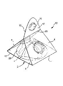
Figure 1 discloses a preferred embodiment of a single use, foldable dispenser
adapted to be used for storing and dispensing a quantity of an adhesive
lavatory treatment
composition which dispenser has two arms in a folded configuration wherein
both of the
arms are folded rearwardly of the opening of the cavity, while Figs. 2 and 3
depict the
same dispenser of Fig. 1 in an unfolded, generally planar configuration. Fig.
4 depicts
the same dispenser of Fig. 1, which incorporates a cover film 50 (alternately,
cover
means) spanning across the open end 2 (alternately, opening 2) of the cavity
4. In the
embodiment illustrated in Figs. 1 ¨4, the dispenser 10 includes a pair of
foldable arms
6,8 which are flexibly or hingedly affixed or depend from a part of the base
9. Such
attachment of the foldable arms 6,8 may be in accordance with any means or
construction; here is illustrated that each of the foldable arms 6,8 depend
from the base 9
via hinges or hinge lines 11, 13 which may be integrally formed parts of the
dispenser 10.
As is most easily understood from Figs. 2 ¨ 4, in a first configuration both
of the foldable
21
CA 02888179 2015-04-14
WO 2014/072677
PCT/GB2013/052502
arms 6,8 extend outwardly from the base 9 such that the foldable arms 6,8 are
essentially
or generally coplanar with the face 14 of the base 9. In this manner, an
"unfolded"
configuration of the dispenser 10 can be provided. The dispenser 10 may assume
a
further second configuration, wherein at least one, and here both of the
foldable arms 6,8
are folded rearwardly of the base 9 and cavity 4 so that at least a portion of
each of the
arms extends above and/or behind the cavity 4, as is readily understood with
reference to
Fig. 1. As is seen therefrom, the two rearwardly folded arms 6,8 contact each
other, and
at least a distal part 15, 17 of each arm 6,8 come into an interfacial laminar
contact. As is
illustrated in Fig. 1, each arm 6,8 forms an interlocking contact therebetween
by virtue of
one or more interlocking means which may be provided with the dispenser 10,
and/or
which are incorporated into the construction of one or both of the arms 6,8.
In the
depicted embodiment, interlocking means are provided by virtue of a plug 19
which
extends out rearwardly from a rear surface 23 of a part of the arm 8, more
specifically
from a distal part 15 thereof, which plug 19 forms a cooperating friction or
interference
fit with recess 20 which extends forwardly from a front surface 24 of a part
of the arm 6,
more specifically from a distal part 17 thereof, such that when arms 6, 8 are
folded into
configuration depicted on Fig. 1, the plug 19 enters the recess 20 and is
retained by
means of an interference or friction fit. This configuration may be further
facilitated by a
pair of secondary hinges or hinge lines 25, 26 which may be integrally formed
parts of
the respective arms 6,8 of the dispenser 10, and which are located between the
hinges or
hinge lines 11, 13 and the respective ends 27, 28 of arms 6,8. As is seen from
Fig. 1,
only part of the arms 6,8 form an interfacial contact in the region of the
plug 19 and
recess 20.
As is further understood from Figs. 1 ¨ 4, the base 9 includes a cavity 4
which is
adapted to receive, and to retain a quantity such as a unit dose of a
material, e.g., an
adhesive lavatory treatment composition. In the depicted embodiment, a
generally
hemispherical configuration of a cavity 4 is illustrated it is however to be
clearly
understood that any other configuration for the cavity, including a
partitioned cavity,
having two or more recesses or parts is clearly contemplated to be within the
scope of the
instant invention. It is also to be understood that in Figs. 1 ¨ 4 the cavity
4, for the sake of
convenient illustration, is depicted as being hollow and contains no such
material. The
22
CA 02888179 2015-04-14
WO 2014/072677
PCT/GB2013/052502
cavity 4 nonetheless defines a volume between the face 14 of the base 9 and
the cavity
wall 29 which is adapted to retain a quantity of such a material. As is
clearly visible from
these drawing figures, the cavity wall 29 extends rearwardly from a rear
surface 23 such
that it extends beyond the generally planar surface of the face 14 of the base
9, and of the
arms 6, 8 as is clearly depicted on Fig. 2.
In certain embodiments, as is illustrated on the present embodiment of Figs. 1
¨4,
the device 10 may optionally further include one or more, here two,
compression means
31, 32 which are configured and/or adapted to provide a contact surface
between the
respective compression means 31, 32 and at least a part of the cavity wall 29.
In
preferred embodiments, when the device 10 assumes a configuration of Fig. 1,
the
compression means 31, 32 may aid in providing a compressive force which bears
against
the cavity wall 29 which may facilitate the release of any composition
contained within
the cavity 9 such that it exits outwardly via the open end 2 of the cavity 4,
when distal
parts 15, 17 of each arm 6,8 are grasped by a user's fingers and moved
together to
assume a configuration as illustrated in Fig. 1. In the illustrated
embodiment, a
compression means 31, 32 is integrally formed within sections of the arms 6, 8
and
extend outwardly from a rear surface 23 of a part of each arm 6,8 and includes
a sloped
flat face 33, 34 which is angled downwardly in the direction of the cavity
wall 29 and in
the direction of the base 9. Advantageously, the dimensions of each of the
compression
means 31, 32 and the angle of the sloped flat face 33, 34 are such that when
the device 10
is folded to assume the configuration as depicted on Fig. 1, that at least a
part of each of
the compression means 31, 32 and preferably, at least a part of the sloped
flat face 33, 34
of each compression means 31, 32 comes into contact with it the cavity wall 29
rearwardly of both the base 9 and the open end 2 of the cavity.
Fig. 4 illustrates the presence of a cover film 50 (alternately a cover means)
which
spans across the open end of the cavity and is removed therefrom prior to
dispensing any
material contained within the cavity 4. As is understood from a review of the
figure, the
cover film 50 is removably affixed to part of the face 14 of the base 9 and
covers the
open end (not visible) of the cavity. Prior to the dispensing of any
composition which
may be (or is) contained within the cavity 4, a part of the cover film, e.g.
an extending tab
52, may be grasped by a user (such as between two fingers, such as a thumb and
index
23
CA 02888179 2015-04-14
WO 2014/072677
PCT/GB2013/052502
finger) and pulled away from the base 9 such that the open end 2 of the cavity
4 is
exposed, which concurrently also exposes the contents of the cavity, and
permits the
treatment composition to be dispensed from the dispenser 10 via said open end
2 (or
opening 2). Such a cover film 50 may be attached, such as by suitable adhesive
between
at least a part of the cover film 50 and one or more parts of the base 9, such
that it can be
removed in the manner as described herein.
Except for the cover film 50 which is a discrete and separable element of the
depicted embodiment of the dispensing device 10, advantageously the dispensing
device
is formed from a single material, preferably a moldable sheet-like material
which can
10 be appropriately configured to assume a configuration and/or to function
as described
herein. The cover film 50 (or cover means) is advantageously a flexible
material, such
as a flexible synthetic polymeric film or a metal foil or metalized film which
can be
adhered to, and conveniently peeled away from the dispensing device 10 by a
consumer
just prior to the dispensing of a quantity (e.g. unit mass, unit, unit dose)
of a composition
(e.g, adhesive composition, adhesive lavatory treatment composition) onto a
surface such
as a part of a lavatory appliance (e.g., toilet bowl, bidet) or any other
surface to which the
composition may be dispensed and preferably adhered. The cover film 50 (or
cover
means 50) may also be formed of a stiff or rigid material such as a plate or
cap which
also may be adhered to, or at least partially inserted within the cavity 4,
e.g. such that a
part of the cover means 50 extends into the cavity 4 in the proximity of the
opening 2,
such by forming an interference fit or friction fit between parts of the cover
means 50 and
part of the cavity 4 or other part or parts of the dispensing device 10.
Figs. 5 and 6 illustrate a further embodiment of a dispensing device according
to
the present invention, which is substantially similar to the embodiment
discussed with
reference to Figs. 1 ¨ 4. In this further embodiment, the dispensing device
differs only in
that (a) it includes a release film 70 which is in part affixed to, or adhered
to a part of the
base 9, or cavity 4, and which extends into the interior of the cavity 4 such
that it is in
interfacial contact with at least part of, preferably most of, the cavity wall
29 and
separates the cavity wall 29 from (b) an adhesive treatment composition 60
contained
within the cavity 4. It is particularly preferred that the release film 70 is
only partially
adhered to parts of the cavity wall 29 and/or the base 4 (or other parts of
the dispenser 10)
24
CA 02888179 2015-04-14
WO 2014/072677
PCT/GB2013/052502
such that it remains flexible, in such a manner that when the treatment
composition is
released from the dispensing device 10 via the open end 2 of the cavity 4, at
least a part
of the release film 70 extends outwardly from the cavity 4, and remains
attached to the
treatment compositions. As the user withdraws the dispensing device away from
the
surface to which the treatment composition has been applied, the release film
70
separates from the applied treatment composition but remains adhered to the
dispensing
device 10. In the embodiment depicted on Figs. 5 and 6, the release film 70 is
adhered
only along two bonding points 72, depicted as dotted lines on opposite sides
of the open
end 2 of the cavity 4; is be understood that the release film 70 is bonded at
these bonding
points 72 at the face 14 of the base 9, but otherwise remains flexible and
unbonded to
other points of the dispensing device 10. It is to be further understood that
in certain
preferred embodiments the release film 70 is adhered or otherwise attached to
only one
part of the dispensing device. It is also be understood that the release film
70 is of
sufficient dimensions such that it extends into the cavity 4 where it can
assume a position
as depicted in the cross-sectional view provided by Fig. 5.
As can now be better understood in conjunction with Figs. 5 and 6, the release
film 70 act as a barrier layer between the adhesive treatment composition
(e.g, adhesive
lavatory treatment composition) and the cavity wall 29. Advantageously, the
adhesive
characteristics or strength of the adhesive treatment composition to the
release film is
generally substantially lower or poorer than the adhesive characteristics or
strength of the
adhesive treatment composition to the surface to which the adhesive treatment
composition is intended to be applied, e.g., a ceramic surface, a surface of a
lavatory
appliance, the interior of a toilet bowl, bidet, shower stall, tiled or
ceramic surface, such
that when a user (e.g. a consumer) of the dispensing device positions the
adhesive
treatment composition against said surface, and optionally but preferably also
applies
some pressure against the cavity wall 29, the adhesive treatment composition
adheres to
the said surface, and when the user withdraws the dispensing device the
release film 70
gently peels away from the now adhered adhesive treatment composition. Any
material
which can be formed into such a release film 70 and which has such adhesive
characteristics or strength is described herein can be utilized, and selection
of such
material can be determined by a skilled artisan, once the specific chemical
composition
CA 02888179 2015-04-14
WO 2014/072677
PCT/GB2013/052502
and the nature of the adhesive treatment composition is established or
selected, and such
an adhesive composition is specified for use with a dispensing device as
described herein.
Any number of such materials may be used. By way of nonlimiting example,
preferred
and exemplary materials useful for forming the release film 70 (as well as at
least part of
the cover means 50) include those which exhibit good oxygen barrier properties
(preferably exhibiting an oxygen barrier property of not more than about 4000
cm3
/m2 d kPa, preferably not more than about 2000 cm3 wri /m2 d kPa (at 23 C and
95%
relative humidity), include metal foils, metalized polymeric films, a coated
paper or other
coated fibrous material (e.g, a silicone coated paper) but especially
preferably are thin
flexible films formed from synthetic polymers which may be based on one or
more
comonomers, and minor amount of other materials such as colorants,
plasticizers, etc.
which may included in their compositions in order to supply a desired
technical or
aesthetic feature to the synthetic polymer films. Non-limiting examples of
such films
include those based on or comprising one or more of: polycarbonates,
polyacrylics such
as poly(methylmethacrylate), polyalkylene terephtalates such as poly(ethylene
terephtalate) and poly(butylene terephtalate), polyvinyl alcohols, polyesters,
polyamides
(such as Nylon materials) and especially polyolefins such high density
polyethylene
(HDPE), low density polyethylene (LDPE) and linear low density polyethylene
(LLDPE), each of which polymer films may also optionally minor amounts of
other
materials such as colorants, plasticizers, etc. as well. A particularly
preferred polymer
film includes films based on polyvinylidine chloride (PVDC) which may include
one or
more additional monomers, polymer films based on polyethylene which may
include one
or more additional monomers as well (such as "SARAN" film, ex. S.C. Johnson &
Son
Co.) which are amongst preferred materials for the release film 70. The
release film may
also be a laminate of two or more different materials. The thickness of the
release film
70 may vary widely, and is in part a function of the relative stiffness of the
material used
to form the release film 70; again, most advantageously a flexible sheet-like
film is
preferred for use. Where the cover film 50 (cover means 50) is a more rigid or
stiff
element such as a plate, or molded element, such may be formed of any material
such as
a synthetic polymeric material included those discussed above, a metal, a
metalized
polymeric material, a coated paper or other coated fibrous material (e.g, a
silicone coated
26
CA 02888179 2015-04-14
WO 2014/072677
PCT/GB2013/052502
paper, a wax coated paper, a paper having a layer of a synthetic polymer) as
well as
laminates containing one or more of the above, by any suitable means such as
by
stamping, folding as well as molding (thermoplastic or thermosetting) molding
processes
to form a suitably dimensioned cover means 50 for a dispensing device 10 of a
desired or
suitable configuration.
As an alternative to the release film 70 disclosed and discussed with
reference to
Figs. 5 and 6, the same embodiment may instead be provided with a release
material
which is present within and/or extends into the cavity 4, which release film
forms a
barrier between the contents of the cavity of the dispenser and the dispenser
itself, here
the cavity wall 29. Such a release material may be any article or composition
which may
be applied to the cavity wall 29 and which forms at least a partial barrier
layer, but
preferably a total barrier layer between the adhesive composition contained by
the
dispenser 10 within the cavity 4, and the cavity wall 29. Advantageously the
adhesive
characteristics or strength of the adhesive composition to the release
material is generally
substantially lower or poorer than the adhesive characteristics or strength of
the adhesive
treatment composition to the surface to which the adhesive treatment
composition is
intended to be applied, e.g., a ceramic surface, a surface of a lavatory
appliance, the
interior of a toilet bowl, bidet, shower stall, tiled or ceramic surface, such
that when a
user (e.g. a consumer) of the dispensing device positions the exposed adhesive
treatment
composition against said surface, and optionally but preferably also applies
some
pressure against the cavity wall 29, the adhesive treatment composition
adheres to the
said surface, such that when the user withdraws the dispensing device most ( >
75%,
preferably > 90%) of the adhesive composition exits the device 10. Any
material which
can be formed into such a release material, having such adhesive
characteristics or
strength is described herein and which can be applied to the device 10 and
preferably
within the cavity 4 can be utilized. The selection of such material can be
determined by a
skilled artisan, once the specific chemical composition and the nature of the
adhesive
treatment composition is established or selected, and such an adhesive
composition is
specified for use with a dispensing device as described herein.
In certain preferred embodiments, the release material 70 is a fluid or liquid
material, such as a pourable, flowable or sprayable material which exhibits
such adhesive
27
CA 02888179 2015-04-14
WO 2014/072677
PCT/GB2013/052502
characteristics or strength as described above. The release material in such a
physical
form is preferred for use as such can be conveniently applied such as by
coating,
spraying, dipping, brushing, a quantity of the release material onto a part of
parts of the
device 10. It is to be understood that it is not in all aspects necessary that
the entire
interior of the cavity 4 need be coated by the release material as some
instances, only a
partial coverage of the cavity wall 29 may be required and indeed preferable.
For
instance, it may be desired that one or more small areas of the cavity wall 29
be uncoated
by the release material, and thereby allow for physical interfacial contact
between the
adhesive treatment composition and a portion of the uncoated cavity wall 29
thereby
allowing one or more points of adhesion between the mass of the adhesive
treatment
composition and the cavity wall 29 which may aid in its retention within the
cavity 4.
Alternatively, the entire cavity wall 29 may be fully coated by the release
material 70 to
form a complete barrier between the cavity 4 and the adhesive treatment
composition
contained within.
Non-limiting examples of such release materials include virtually all
materials
whose adhesive composition to the release material is generally substantially
lower or
poorer than the adhesive characteristics or strength of the adhesive treatment
composition
to the surface to which the adhesive treatment composition is intended to, or
to which the
adhesive treatment compositions are ultimately applied. Such include
hydrophobic
liquids such as glycerine and paraffin oil, as well as petroleum distillates
and/or
petroleum products, and also paraffinic oils usually based on n-alkanes,
naphthenic oils
including those based on cycloalkanes, aromatic oils such as those based on
aromatic
hydrocarbons, mineral oil, as well as technical grade mixtures of hydrocarbons
may be
used as or in the organic solvent. Examples of the latter include paraffinic
hydrocarbons
including both linear and branched paraffinic hydrocarbons; the former are
commercially
available as NORPAR solvents (ex. ExxonMobil Corp.) while the latter are
available as
ISOPAR solvents (ex. ExxonIVIobil Corp.) Further useful release materials
include one
or more oxyalkylenated compounds, which are may be liquids or pasty at room
temperature (20 C). Exemplary suitable oxyalkylenated compounds include
polyethylene
glycols, polyethylene glycol esters and/or polypropylene glycol esters,
polyethylene
glycol ethers and/or polypropylene glycol ethers, alkoxylated acyl
derivatives,
28
CA 02888179 2015-04-14
WO 2014/072677
PCT/GB2013/052502
ethoxylated acyl polyol derivatives, oxyalkylenated (especially)
oxyethylenated triesters
of glycerol and of fatty acids, and mixtures thereof, each having a minimum
molecular
weight of about 100, preferably about 200, and especially preferably of at
least about
250. Non-limiting examples of suitable polyethylene glycols which may be used
in the
composition of the invention include ethylene oxide polycondensates having a
number of
ethylene oxide (EO) units of greater than 5, and preferably greater than about
20. Non-
limiting examples of such polyethylene glycols include polyethylene glycol
comprising
75 EO (CTFA name: PEG-75), and polyethylene glycol comprising 150 EO (CTFA
name: PEG-150) and polyethylene glycol comprising 7,000 EO (CTFA name: PEG-
7M).
Figs. 7 ¨ 10 depict a further embodiment of a dispensing device 10 according
to
the invention. The depicted dispensing device 10 includes a cavity 4, and a
single
foldable arm 6 which may be hinged around the base 9. In the embodiment
illustrated, the
cavity 4 contains a quantity of an adhesive treatment composition 60, which
cavity 4 also
includes an open end 2. In an initial configuration illustrated on Fig. 8, the
arm 6 is
.. folded forwardly such that at least part of the arm 6 is used to form a
cover means 50
overlapping the open end 2 of the cavity 4 of the base 9, which seals the
adhesive
treatment composition from the ambient environment. In a second configuration
as is
depicted on Figs. 7, 9 and 10, the arm 6 is folded away from the open end 2 of
the cavity
of the base 9, preferably such that the arm 6 is generally coplanar with the
face 14 of the
base 9, as is more clearly visible from these figures.
Fig. 10 depicts an embodiments of this further dispensing device 10, wherein
the
dispensing device 10 further includes a release film 70 which is affixed to
only parts of
the base 9 and extends into the interior of the cavity 4 such that it is in
interfacial contact
with at least part of, preferably most of the cavity wall 29. The release film
70 separates
the cavity wall 29 from the adhesive treatment composition 60 contained within
the
cavity 4. Similarly to the embodiment discussed with reference to Figs. 5 and
6, the
release film 70 is only partially adhered to parts of the cavity wall 29
and/or the base 4
(or other parts of the dispenser 10) such that it remains flexible, so that
when the
treatment composition is released from the dispensing device 10 via the open
end 2 of the
cavity 4, at least a part of the release film 70 extends outwardly from the
cavity 4. Such is
illustrated with reference to Fig. 11, which depicts a configuration of the
dispensing
29
CA 02888179 2015-04-14
WO 2014/072677
PCT/GB2013/052502
device 10 according to Figs. 7¨ 11 immediately after a quantity of an adhesive
treatment
composition 60 has been adhered to the sidewall "SW" of the lavatory
appliance, here a
toilet bowl "TB" at a point below the rim "R" such that the adhesive treatment
composition 60 is in the path of flush water released into the toilet bowl
from beneath the
rim. In the embodiment depicted on Figs. 5 and 6, the release film 70 is
adhered only
along two bonding points 72, depicted as dotted lines on opposite sides of the
open end 2
of the cavity 4. It is to be understood that the release film 70 is bonded at
these bonding
points 72 at the face 14 of the base 9, but otherwise remains flexible and
unbonded to
other points of the dispensing device 10. It is also understood that the
release film 70 is of
sufficient dimensions such that it extends into the cavity 4 where it can
assume a position
as depicted in the cross-sectional view provided by Fig. 10. As is most
clearly understood
with reference to Fig. 11, as the dispensing device 10 is withdrawn away from
the
treatment composition which has been adhered to the sidewall SW of the toilet
bowl TB,
the release film 70 is of sufficient flexibility that while it initially
remains in contact with
the treatment composition as it is withdrawn from the interior of the cavity 4
and in the
figure assumes a "bowed" configuration as it is retained to the face 14 of the
base 9 by
the bonding points 72 on opposite sides of the cavity 4. As the user further
withdraws the
dispensing device 10 way from the sidewall SW and the now adhered treatment
composition, the release film separates from the now adhered treatment
composition 60.
Although not illustrated in Fig. 11, it can be readily understood with
reference thereto
that according to this embodiment of a dispensing device 10, a user or
consumer may grip
the arm 6 between one or more fingers and the palm of a hand, and place the
thumb of the
hand behind the cavity wall 29 such that the thumb can exert an amount of
compression
against this cavity wall 29 and urge the adhesive treatment composition 60
outwardly
therefrom and against the surface to which the adhesive treatment composition
60 is
adhered, here the sidewall SW of the toilet bowl TB.
Figs. 12¨ 14 illustrate a still further embodiment of a dispensing device
according
to the present invention which is similar in many respects to the embodiment
corresponding to Figs. 7 ¨ 11, which differs substantially only in that two
arms 6, 8 are
included, and that in a first configuration illustrated on Fig. 13. arm 6 is
folded to overlap
both a part of arm 8 and comes into interfacial contact there with, and
concurrently also
CA 02888179 2015-04-14
WO 2014/072677
PCT/GB2013/052502
form a cover means 50 overlapping the open end 2 of the cavity 4 of the base
9, which
seals the adhesive treatment composition 60 from the ambient environment.
Although
not specifically illustrated, it is nonetheless to be understood that in the
first
configuration, a suitable adhesive may be present between the overlapping
parts of the
arms 6 and 8, and/or at least in the region of the cover means which overlaps
the open
end 2 of the cavity 4 of the base 9, which adhesive may retain the arms 6, 8
of the device
in the configuration depicted in that figure. In a second configuration as is
depicted on
Fig. 12, arm 6 is folded away from arm 8 as well as from the open end 2 of the
cavity of
the base 9, preferably such that the each of arms 6, 8 are generally coplanar
with the face
10 14 of the base 9, as is more clearly visible from these figures. In such
a configuration,
the adhesive treatment composition is exposed to the ambient environment via
the open
end 2 of the base 9. Thereafter, as is shown with reference to Fig. 14, the
two arms 6, 8
may be folded rearwardly behind the cavity 4, and grasped between two fingers
of a
hand, and the exposed adhesive treatment composition can be directed towards a
surface
"S" to which it is to be applied, and adhered.
It is to be understood that in any of the foregoing embodiments, only a single
bonding point, or more than two bonding points 72 between the release film 70
and the
face 14 of the base 9 (or any other part of the dispensing device) may be
provided.
A further embodiment of a dispenser is illustrated on Figs. 15 ¨ 17, which in
many respects it similar to the embodiment disclosed and discussed with
reference to
Figs. 1 ¨ 6. In the embodiment of Figs. 15 ¨ 17, the dispenser 10 is
illustrated in an
unfolded, generally planar configuration in a top plan view in Fig. 15, and in
a side or
elevation view in Fig. 16, while in Fig, 17 the dispenser is in a folded
configuration. For
ease of illustration in these figures, the dispenser 10 is shown having a
cavity 4 which is
hollow and contains no material.
As illustrated the dispenser 10 includes a pair of foldable arms 6,8 which are
flexibly or hingedly affixed or depend from a part of the base 9 via hinges or
hinge lines
11, 13 which are integrally formed parts of the dispenser 10. Each of the
foldable arms 6,
8 include a at least a distal part 15, 17 which comes into contact when the
dispenser
assumes a folded configuration as depicted on Fig. 17. The distal parts 15, 17
form an
interlocking contact by virtue of one or more interlocking means, here a plug
19 which
31
CA 02888179 2015-04-14
WO 2014/072677
PCT/GB2013/052502
extends out rearwardly from a rear surface 23 of a part of the arm 8, more
specifically
from a distal part 15 thereof, which plug 19 forms a cooperating friction or
interference
fit with recess 20 which extends forwardly from a front surface 24 of a part
of the arm 6.
In the configuration of Fig. 17, the plug 19 enters the recess 20 and is
retained by means
of an interference or friction fit. This configuration is facilitated by a
pair of secondary
hinges or hinge lines 25, 26 which are integrally formed parts of the
respective arms 6,8
of the dispenser 10, and which are located between the hinges or hinge lines
11, 13 and
the respective ends 27, 28 of arms 6,8. As is understood from Fig. 17, only
part of the
arms 6,8 form an interfacial contact in the region of the plug 19 and recess
20.
As further depicted on Figs. 15 ¨ 17, the base 9 of the dispenser 10 includes
a
cavity 4 which is adapted to receive a unit dose of a material, e.g., an
adhesive lavatory
treatment composition. Cavity wall 29 extends rearwardly from a rear surface
23 such
that it extends beyond the generally planar surface of the face 14 of the base
9, and of the
arms 6, 8. The dispenser 10 further includes a pair of compression means 31,
32 which
are configured and/or adapted to provide a contact surface between the each of
the
compression means 31, 32 and at least a part of the cavity wall 29. In
preferred
embodiments, when the device 10 assumes a configuration of Fig. 17, the
compression
means 31, 32 may aid in providing a compressive force which bears against the
cavity
wall 29 which may facilitate the release of any composition contained within
the cavity 9
such that it exits outwardly via the open end 2 of the cavity 4, when distal
parts 15, 17 of
each arm 6,8 are grasped by a user's fingers and moved together to assume a
configuration as illustrated in Fig. 1. In such a folded configuration, the
generally bowl
shape configuration of the compression means 31, 32 also provides for
convenient
placement of a fingertip of a user's hand within respective fingertip
concavities 74, 76 of
the compressive means 31, 32 at or proximate to the base 80, 82 of each
compression
means 31, 32. In such a preferred embodiment as illustrated on Figs. 15 ¨ 17
the exterior
face 83, 84 of each compression means 31, 32 includes a face region 85 which
has a
configuration which complements that part of the cavity wall 29 with which it
comes into
contact. Preferably the face region 85 is coincident with, or is proximate to
the face 83,
84 of each compression means 31, 32. Thus, when the folded dispenser 10 is
grasped by
a user, such as between a thumb "TB" and forefinger "FF", the tips of each of
these
32
CA 02888179 2015-04-14
WO 2014/072677
PCT/GB2013/052502
fingers is within the of each of the respective fingertip concavities 74, 76
of the
compressive means 31, 32, and the face region 85 of each of the compressive
means 31,
32 is urged against a respective part of the cavity wall 29 with which parts
of each of the
compressive means 31, 32 comes into contact. As in Fig. 15¨ 17, these face
region 85
include shallow depressions which complement the curved cavity wall 29, any
pressure
exerted by a user via the fingertips of the thumb TB and forefinger FF is
directly
transmitted as a compressive force via the face region 85 and against the that
part of the
cavity wall 29 with which it comes into contact, which in turn may impart a
compressive
pressure against any material contained within the cavity 4, inducing its exit
via the
opening 2.
The embodiment illustrated on Figs. 15 ¨ 17 also illustrates a release film 70
is
adhered only along only one bonding region 72, depicted as a dotted line on
opposite
sides of the open end 2 of the cavity 4; is be understood that the release
film 70 is bonded
at this bonding region 72 at the face 14 of the base 9, but otherwise remains
flexible and
unbonded to other points of the dispensing device 10. Such is better
understood with
reference to Fig. 16 which illustrates that the release film 70 is held only
at one point (one
bonding point, one bonding region) to the base 9 or any other part of the
dispensing
device 10. Thus, after the adhesive material is delivered from the device 10,
the released
release film 70 may be suspended in a flag-like manner as depicted. It is also
be
understood that the release film 70 is of sufficient dimensions such that it
extends into the
cavity 4 where it forms a barrier layer between any adhesive material within
the cavity 4
and the cavity wall 29. Also, while not specifically illustrated on Figs. 15 ¨
20 it is
clearly contemplated that a cover film 50 (or, cover means 50) may also be
included in
the dispenser 10, e.g, as illustrated on Fig. 4.
Figure 18 illustrates an array 90 of dispensers 10, each of which includes a
cavity
4 which is adapted to receive a unit dose of a material, e.g., an adhesive
lavatory
treatment composition, Each of the dispensers 10 is removably affixed or
connected to
an adjacent dispenser 10 by a separable connector means, which is the present
embodiment is a perforated or frangible connector part 92 which retains
adjacent
dispensers 10 in a fixed position until one adjacent dispenser 10 is separated
from a next
adjacent dispenser 10 by separating the connector means, e.g, by tearing,
folding,
33
CA 02888179 2015-04-14
WO 2014/072677
PCT/GB2013/052502
bending, pulling or other suitable action. Each of the individual dispensers
10 illustrated
on Fig. 18 are similar in most respects to the dispenser described with
reference to Figs. 1
- 6, but in this illustrated embodiment excludes Each dispenser 10 of the
array 90 is
essentially identical, and each includes a cavity 4 adapted to or containing a
quantity of
an adhesive treatment composition, an open end 2 (or opening 2) in a base 9
which
allows for the dispensing of the said composition from the dispenser 10, a
pair of foldable
arms 6,8 which are flexibly or hingedly affixed or depend from a part of the
base 9, a
plug 19 and a recess 20. Additionally each of the dispensers 10 includes a
separable
connector part 92 which connects to at least one adjacent dispenser 10. While
not shown
it is to be understood that one or more of the dispensers 10 may further
include
compression means such as the compression means 31, 32 of Figs. 1 ¨6, and/or a
cover
film 50 (alternately a cover means) which spans across the open end of the
cavity and is
removed therefrom prior to dispensing any material contained within the cavity
4 such as
in Fig. 4, and/or a release film 70 which is in part affixed to, or adhered to
a part of the
base 9, or cavity 4, and which extends into the interior of the cavity 4 such
that it is in
interfacial contact with at least part of, preferably most of, the cavity wall
29 and
separates the cavity wall 29 from (b) an adhesive treatment composition 60
contained
within the cavity 4, such as depicted on Figs. 5 and 6, and 15 ¨ 17.
In an embodiment as depicted on Fig. 18, such an array 90 advantageously
provides a vendible form of the dispensers 10 of the invention which provides
a highly
visible yet compact retail display, whereby one or of the individual
dispensers 10 can be
separated from the array 90 as desired by an ultimate purchaser of the
dispenser(s) 10.
The array 90 is particularly well suited as a hanging display.
The array 90 of a plurality of dispensers 10 is also technically advantageous
as
during a manufacturing process, a plurality of empty dispensers 10 may first
be formed
and by virtue of the connector parts 92, and thereafter each of the cavities 4
filled in a
simultaneous or sequential process. For example wherein an array of an integer
number
"n" of individual dispensers 10 is formed, such is frequently in a generally
planar
configuration and by virtue of the connector means, the relative placement of
the empty
cavities 4 is fixed, which is advantageously in an adjacent and/or linear
arrangement as
illustrated on Fig. 18. Such placement thus facilitates the filling of
adjacent or sequential
34
CA 02888179 2015-04-14
WO 2014/072677
PCT/GB2013/052502
arrays from one filling station having one nozzle in which case the array 90
is moved in a
linear fashion whereby an empty cavity 4 is filled, and then the nozzle or the
array 90 is
moved in a linear direction and the next sequential empty cavity 4 of the next
dispenser
is filled. Alternatively wherein a generally planar sheet of individual
dispensers 10 is
5 formed as an array 90, the array may be provided to a filling station
which has a plurality
of filling nozzles configured to preset positions which correspond to the
configuration of
the empty cavities 4 of the array 90. In such a manner, the preformed array 90
of empty
dispensers 10 may be conveniently simultaneously filled by operating the
filling station
to simultaneously deliver the adhesive composition from a plurality of nozzles
at the
10 same time. In the foregoing process, in the array 90, the number "n" of
individual
dispensers 10 is advantageously in the range of 2 to about 80. preferably from
about 2 to
about 60. In an alternative process, a the array 90 of a plurality of
dispensers 10 are
formed on a roll or spool, with adjacent empty dispensers 10 attached by one
or more
intermediate connector means. In the embodiment show, the connector means 92
extend
.. from parts of the base 9 of each dispenser 10, but it is to be understood
that the connector
means may be positioned on any part of the dispenser 10, e.g, at parts of the
base 4 and/or
part of the arms 6, 8 thereof Where such an array 90 is configured so that the
placement
of adjacent cavities 4 are colinear, (as indicated by representative dashed
center line
"Li" on Fig. 18) such provides for the convenient subsequent filling of the
adjacent
cavities 4 as the spool or roll may be unrolled, and directed in a linear
direction under one
or more filling nozzles which may be placed in a linear arrangement as well
and spaced
in a suitable configuration to correspond to that of the empty cavities such
that empty
cavities 4are positioned under or adjacent to an empty nozzle(s) and filled.
The
foregoing processes provide non-limiting examples of advantageous production
processes
of arrays 90 of individual dispensers 10. The embodiment of the array 90 is
considered
to illustrate a "single linear array" as a single series of adjacent empty
dispensers 10 are
attached by one or more intermediate connector means and wherein a single line
or row
of cavities 4 are colinear along a single center line Ll.
Fig. 19 depicts an embodiment of an array 90, here in the form of a "dual
linear
array" wherein the array includes at least two rows of parallel individual
dispensers 10
such that the cavities 4 present are positioned along two parallel lines, a
first center line
CA 02888179 2015-04-14
WO 2014/072677
PCT/GB2013/052502
"Li" and a second center line "L2". Advantageously as illustrated the first
center line
and the second center lines are parallel with respect to each other, which
thereby
establishes the configuration and relative placement of the cavities 4 of
adjacent
dispensers 10. Here the individual dispensers 10 are essentially the same as
described
with respect to those of Fig. 18, but comprise further connector means 92
which in
addition to the base 4, also extend from parts of the arms 6,8 and more
specifically from
the ends 27, 28 thereof. The embodiment of the array 90 is considered to
illustrate a
"dual linear array" as two series of adjacent empty dispensers 10 are attached
by one or
more intermediate connector means and wherein a two lines or rows of cavities
4 are
colinear and in this embodiment, parallel with respect to one another.
It is to be clearly understood that parts and elements disclosed in one of the
foregoing configuration or otherwise depicted upon or discussed with reference
to one or
more of the drawing figures may be utilized in any other embodiment of the
invention.
36