Note: Descriptions are shown in the official language in which they were submitted.
CA 02888247 2015-04-16
WO 2014/062614 PCT/US2013/064938
FLUID DELIVERY SYSTEM WITH HIGH AND LOW PRESSURE HAND MANIFOLD
CROSS-REFERENCE TO RELATED APPLICATIONS
[0001] This application claims the benefit of United States Non-Provisional
Application No.
13/755,883, filed on January 31, 2013 which claims priority to United States
Provisional
Application No. 61/714,872, filed October 17, 2012.
BACKGROUND OF THE INVENTION
Field of the Invention
[0002] This disclosure relates to medical fluid delivery applications and,
particularly, a fluid
delivery system comprising a fluid path set with a high and low pressure hand
manifold for
delivery of one or more medical fluids to a patient undergoing a medical
diagnostic or
therapeutic procedure.
Description of Related Art
[0003] In many medical diagnostic and therapeutic procedures, a medical
practitioner such as
a physician injects a patient with a fluid. In recent years, a number of
injector-actuated syringes
and powered injectors for pressurized injection of fluids, such as contrast
media (often referred
to simply as "contrast", have been developed for use in procedures such as
angiography,
computed tomography (CT), ultrasound, and NMR/MRI. In general, these powered
injectors are
designed to deliver a preset amount of contrast at a preset flow rate.
[00041 Angiography is used in the detection and treatment of abnormalities or
restrictions in
blood vessels. In an angiographic procedure, a radiographic image of a
vascular structure is
obtained through the use of a radiographic contrast which is injected through
a catheter. The
vascular structures in fluid connection with the vein or artery in which the
contrast is injected are
filled with contrast. X-rays passing through the region of interest are
absorbed by the contrast,
causing a radiographic outline or image of blood vessels containing the
contrast. The resulting
images can be displayed on, for example, a video monitor and recorded.
[0005] In a typical angiographic procedure, the medical practitioner places a
cardiac catheter
into a vein or artery. The catheter is connected to either a manual or to an
automatic contrast
injection mechanism. A typical manual contrast injection mechanism includes a
syringe in fluid
connection with a catheter connection. The fluid path also includes, for
example, a source of
1
CA 02888247 2015-04-16
WO 2014/062614 PCT/US2013/064938
contrast, a source of flushing fluid, typically saline, and a pressure
transducer to measure patient
blood pressure. In a typical system, the source of contrast is connected to
the fluid path via a
valve, for example, a three-way stopcock. The source of saline and the
pressure transducer may
also be connected to the fluid path via additional valves, again such as
stopcocks. The operator of
the manual contrast injection mechanism controls the syringe and each of the
valves to draw
saline or contrast into the syringe and to inject the contrast or saline into
the patient through the
catheter connection. The operator of the syringe may adjust the flow rate and
volume of injection
by altering the force applied to the plunger of the syringe. Thus, manual
sources of fluid pressure
and flow used in medical applications, such as syringes and manifolds,
typically require operator
effort which provides feedback of the fluid pressure/flow generated to the
operator. The feedback
is desirable, but the operator effort often leads to fatigue. Thus, fluid
pressure and flow may vary
depending on the operator's strength and technique.
[0006] Automatic contrast injection mechanisms typically include a syringe
connected to a
powered injector having, for example, a powered linear actuator. Typically, an
operator enters
settings into an electronic control system of the powered injector for a fixed
volume of contrast
and a fixed rate of injection. In many systems, there is no interactive
control between the
operator and the powered injector, except to start or stop the injection. A
change in flow rate in
such systems occurs by stopping the machine and resetting the injection
parameters.
Nonetheless, automatic contrast injection mechanisms provide improved control
over manual
apparatuses where successful use of such manual devices is dependent on the
skill of the medical
practitioner operating the device.
[0007] While manual and automated injectors are know in the medical field,
improved fluid
delivery systems adapted for use in medical diagnostic and therapeutic
procedures where one or
more fluids are supplied to a patient during the procedure continue to be in
demand in the
medical field. Additionally, improved fluid transfer sets and flow controlling
and regulating
devices associated therewith, which may be used with fluid delivery systems
for conducting and
regulating fluids flows, are also desired in the medical field. Moreover, the
medical field
continues to demand improved medical devices and systems used to supply fluids
to patients
during medical procedures such as angiography, computed tomography,
ultrasound, and
NMR/MRI.
2
CA 02888247 2015-04-16
WO 2014/062614 PCT/US2013/064938
SUMMARY OF THE INVENTION
[0008] In one embodiment, a fluid path set for a fluid delivery system is
provided and
comprises a manifold comprising a plurality of fluid control valves in series
fluid
communication. A first fluid control valve of the plurality of fluid control
valves comprises a
first port, a second port, and a third port. The third port of the first fluid
control valve is in fluid
connection with a first port of a second fluid control valve. A low pressure
hand-operated syringe
is in fluid connection with the first port of the first fluid control valve,
and a high pressure
syringe is in fluid connection with the second port of the first fluid control
valve. The fluid
control valves may comprise multi-position stopcock valves. The manifold may
further comprise
a manifold housing, and the fluid control valves may be in friction-fit
connection within the
manifold housing.
[0009] The manifold may further comprise an L-shaped manifold housing. The L-
shaped
manifold housing may comprise a longitudinal portion and a lateral portion,
and the second port
of the first fluid control valve may be generally coaxial with the lateral
portion. The lateral
portion may define a tubing retention pathway to accommodate tubing connecting
the high
pressure syringe with the second port of the first fluid control valve. The
tubing retention
pathway may define a tubing bend of approximately 900. The manifold may
further comprise a
manifold housing, and the manifold housing may comprise a stop element to
prevent rotation of
the first fluid control valve to a position that opens a fluid path between
the high pressure syringe
and the low pressure syringe.
[0010] In another embodiment, a fluid delivery system is provided, comprising
a power
injector supporting a high pressure syringe. The fluid delivery system further
comprises a
manifold and a low pressure hand-operated syringe. The manifold generally
comprises a
plurality of fluid control valves in series fluid communication. A first fluid
control valve of the
plurality of fluid control valves comprises a first port, a second port, and a
third port. The third
port of the first fluid control valve is in fluid connection with a first port
of a second fluid control
valve. The low pressure hand-operated syringe is in fluid connection with the
first port of the
first fluid control valve, and the high pressure syringe is in fluid
connection with the second port
of the first fluid control valve. The fluid control valves may comprise multi-
position stopcock
valves. The manifold may further comprise a manifold housing, and the fluid
control valves may
be in friction-fit connection within the manifold housing.
3
CA 02888247 2015-04-16
WO 2014/062614 PCT/US2013/064938
[0011] The manifold may further comprise an L-shaped manifold housing. The L-
shaped
manifold housing may comprise a longitudinal portion and a lateral portion,
and the second port
of the first fluid control valve may be generally coaxial with the lateral
portion. The lateral
portion may define a tubing retention pathway to accommodate tubing connecting
the high
pressure syringe with the second port of the first fluid control valve. The
tubing retention
pathway may define a tubing bend of approximately 900. The manifold may
further comprise a
manifold housing, and the manifold housing may comprise a stop element to
prevent rotation of
the first fluid control valve to a position that opens a fluid path between
the high pressure syringe
and the low pressure syringe.
[0012] In a further embodiment, a fluid path set for a fluid delivery system
is provided and
comprises a manifold comprising a plurality of fluid control valves in series
fluid
communication, each of the fluid control valves comprising a first port, a
second port, and a third
outlet port. The third port of a first of the first fluid control valves is in
fluid connection with the
first port of a second of the fluid control valves, and the third port of the
second fluid control
valve is in fluid connection with the first port of a third of the fluid
control valves. A low
pressure hand-operated syringe is in fluid connection with the first port of
the first fluid control
valve, and a high pressure syringe is in fluid connection with the second port
of the first fluid
control valve. A hemodynamic pressure transducer may be in fluid connection
with the second
port of the third fluid control valve. The fluid control valves may comprise
multi-position
stopcock valves. The manifold may further comprise a manifold housing, and the
fluid control
valves may be in friction-fit connection within the manifold housing.
[0013] The manifold may further comprise an L-shaped manifold housing. The L-
shaped
manifold housing may comprise a longitudinal portion and a lateral portion,
and the second port
of the first fluid control valve may be generally coaxial with the lateral
portion. The lateral
portion may define a tubing retention pathway to accommodate tubing connecting
the high
pressure syringe with the second port of the first fluid control valve. The
tubing retention
pathway may define a tubing bend of approximately 90 . The manifold may
further comprise a
manifold housing, and the manifold housing may comprise a stop element to
prevent rotation of
the first fluid control valve to a position that opens a fluid path between
the high pressure syringe
and the low pressure syringe.
4
85183789
[0013a] According to one aspect of the present invention, there is provided a
fluid path set
for a fluid delivery system, comprising: a manifold comprising a plurality of
fluid control valves
in series fluid communication, wherein a first fluid control valve comprises a
first port of the
first fluid control valve, a second port of the first fluid control valve, and
a third port of the first
fluid control valve, wherein the third port of the first fluid control valve
is in fluid connection
with a first port of a second fluid control valve; a low pressure hand-
operated syringe in fluid
connection with the first port of the first fluid control valve; and a high
pressure syringe in fluid
connection with the second port of the first fluid control valve, wherein the
plurality of fluid
control valves and the high pressure syringe can withstand pressures of 1000-
1200 psi.
10013b] According to one aspect of the present invention, there is provided a
fluid delivery
system, comprising: a power injector including a high pressure syringe
operated by the power
injector; a manifold comprising a plurality of fluid control valves in series
fluid communication,
wherein a first fluid control valve comprises a first port of the first fluid
control valve, a second
port of the first fluid control valve, and a third port of the first fluid
control valve, wherein the
third port of the first fluid control valve is in fluid connection with a
first port of a second fluid
control valve; and a low pressure hand-operated syringe in fluid connection
with the first port
of the first fluid control valve; wherein the high pressure syringe is in
fluid connection with the
second port of the first fluid control valve, and wherein the plurality of
fluid control valves and
the high pressure syringe can withstand pressures of 1000-1200 psi.
[0013c] According to one aspect of the present invention, there is provided a
fluid path set
for a fluid delivery system, comprising: a manifold comprising a plurality of
fluid control valves
in series fluid communication, each of the plurality of fluid control valves
comprising a first
port, a second port, and a third port, wherein the third port of a first fluid
control valve of the
plurality of fluid control valves is in fluid connection with the first port
of a second fluid control
valve of the plurality of fluid control valves, and the third port of the
second fluid control valve
is in fluid connection with the first port of a third fluid control valve of
the plurality of fluid
control valves; a low pressure hand-operated syringe in fluid connection with
the first port of
the first fluid control valve; and a high pressure syringe in fluid connection
with the second port
of the first fluid control valve, wherein the plurality of fluid control
valves and the high pressure
syringe can withstand pressures of 1000-1200 psi.
4a
Date Recue/Date Received 2020-07-27
CA 02888247 2015-04-16
WO 2014/062614 PCT/US2013/064938
[0014] Further details and advantages of the various embodiments described in
detail herein
will become clear upon reviewing the following detailed description of the
various embodiments
in conjunction with the accompanying drawing figures.
BRIEF DESCRIPTION OF THE DRAWINGS
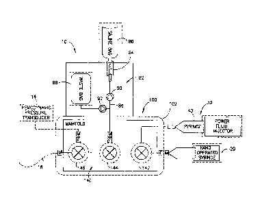
[0015] FIG. 1 is a schematic view of a fluid delivery system including a dual
high and low
pressure hand manifold.
[0016] FIG. 2 is a perspective view of the fluid delivery system of FIG. 1
comprising a fluid
path set incorporating the dual high and low pressure manifold.
[0017] FIG. 3 is another perspective view of the fluid path set incorporating
the dual high and
low pressure manifold as shown in FIG. 2.
[0018] FIG. 4 is an elevational view of the manifold shown in FIGS. 2-3.
[0019] FIG. 5 is a perspective and exploded view of the manifold shown in FIG.
4.
[0020] FIG. 6 is a perspective view of a manifold housing of the manifold
shown in FIG. 4.
[0021] FIG. 7 is an elevational view showing a portion of the manifold shown
in FIG. 4.
[0022] HG. 8 is an end view of the manifold shown in FIG. 7.
[0023] FIG. 9A is transverse cross-sectional view showing an end portion of
the manifold
shown in FIG. 7.
[0024] FIG. 9B is a detail view of Detail 9B in FIG. 9A.
[0025] FIG. 10 is an elevational view of the manifold shown in FIG. 4.
[0026] FIG. 11 is a cross-sectional view taken along lines 11-11 in FIG. 10.
[0027] FIG. 12 is a perspective view showing fluid control valves connected in
series as used
in the manifold shown in FIG. 4.
[0028] FIG. 13 is a top view showing the serially-connected fluid control
valves used in the
manifold shown in FIG. 4.
[0029] FIG. 14 is a cross-sectional view taken along lines 14-14 in FIG. 13.
DESCRIPTION OF THE PREFERRED EMBODIMENTS
[0030] For purposes of the description hereinafter, spatial orientation terms,
as used, shall
relate to the referenced embodiment as it is oriented in the accompanying
drawing figures or
otherwise described in the following detailed description. However, it is to
be understood that
the embodiments described hereinafter may assume many alternative variations
and
85183789
configurations. It is also to be understood that the specific components,
devices, features, and
operational sequences illustrated in the accompanying drawing figures and
described herein are
simply exemplary and should not be considered as limiting.
[0031] Referring to FIG. 1, a fluid delivery system 10 is shown and includes a
dual high and
lower pressure hand manifold 100 adapted for fluid connection to a plurality
of fluid sources.
The fluid sources may include a low pressure, hand-operated syringe 20, a high
pressure, power
injector operated syringe 40, and one or more additional fluid sources or
containers such as fluid
source container 80 in the form of, for example, a saline bag. Referring
further to FIG. 2, the
hand-operated syringe 20 may be a conventional hand-operated syringe
comprising a syringe
barrel 22 with a discharge neck 24 having a rotational tip connector 26 at its
terminal end. The
rotational tip connector 26 may be, for example, a rotational luer connector.
The syringe barrel
22 may be formed with opposed finger grips 28 for the user. Additionally, a
plunger 30 is
disposed in the syringe barrel 22. The plunger 30 may include a proximal
finger grip 32 for the
user.
[0032] The high pressure syringe 40 may be a syringe adapted for mechanical
interface with a
power injector 12, which is schematically represented in FIG. 1. A suitable
high pressure syringe
40 adapted to interface with the power injector 12 may be found in United
States Patent
Application Publication No. 2009/0216192 to Schriver et al.
for teachings related to the high pressure syringe 40 and, further, the power
injector 12. The high
pressure syringe 40 generally comprises an elongated, cylindrical syringe body
42 having a front
or distal end 44 and a rear or proximal end 46. The syringe body 42 generally
defines an
injection section 48 at the distal end 44 and an expansion section 50 at the
proximal end 46. A
generally cylindrical center or working section 52 of the syringe body 42
connects the injection
section 48 and the expansion section 50. The center or working section 52 has
a relatively
uniform outer diameter. The injection section 48 tapers to form an elongated
discharge neck 54,
which has a relatively small inner diameter compared to the inner diameter of
the center or
working section 52. The injection section 48 and discharge neck 54 generally
form the discharge
outlet of the syringe 40. The expansion section 50 accommodates a syringe
plunger (not shown).
The injection section 48 is formed with a hollow alignment flange or tab 56
for orienting and
aligning the syringe 40 in the power injector 12.
6
CA 2888247 2019-12-09
85183789
[0033] Additionally, the proximal end 46 of the syringe body 42 defines an
outward extending
radial lip 58. The radial lip 58 is adapted to engage or contact an electrical
contact switch in the
power injector 12 to activate the electrical switch to identify when the
syringe 40 is properly
loaded in the power injector 12. The radial lip 58 preferably has an outer
diameter that is no
greater than the outer diameter of the center or working section 52 of the
syringe body 42 so that
the syringe 40 may be smoothly accepted into a pressure jacket (not shown)
associated with the
power injector 12 during a syringe-loading procedure. A tip connector 60 is
connected to the
terminal end of the discharge neck 54 and a length of tubing 62, typically
high pressure braided
or coextruded tubing, extends from the tip connector 60 to place the high
pressure syringe 40 in
fluid connection with the manifold 100. Details of the tip connector 60 may be
found in PCT
Application No. PCT/US12/37491 filed May 11, 2012, (PCT Publication No.
WO/2012/155035) .
[0034] Referring further to remaining FIGS. 3-14, the manifold 100 includes a
manifold
housing 102 formed to support a plurality of fluid control valves 140 that are
connected in series
with one another. The manifold housing 102 is generally L-shaped and defines a
longitudinal
portion 104 and a lateral portion 106. The lateral portion 106 is generally
orthogonal to the
longitudinal portion 104. The manifold housing 102 is formed with a generally
closed first side
108 and has a second side 110 that defines a recessed area or pocket 112
adapted to accept and
support the fluid control valves 140. The recessed area or pocket 112 is
defined by a side wall
114 that extends around the perimeter of the recessed area or pocket 112.
Within the recessed
area 112, the manifold housing 102 is formed with a plurality of snap-
fit/friction-fit connection
points or locations 116 to engage the body of the respective fluid control
valves 140. Respective
side openings 118 are defined in the manifold housing 102 in the area of the
connection elements
at locations 116. The snap-fit/friction-fit locations 116 are formed by
individual flange elements
120 formed integrally with the manifold housing 102 and within the recessed
area 112. The
flange elements 120 secure the fluid control valves 140 in the respective snap-
fit/friction-fit
locations 116. Additional port openings 122 are defined in the manifold
housing 102 in the area
of the connection elements at locations 116 to accommodate fluid ports of the
fluid control
valves 140.
[0035] The lateral portion 106 of the manifold housing 102 defines a tubing
retention pathway
124. The tubing retention pathway 124 defines a tubing bend of approximately
90 to allow for
7
CA 2888247 2019-12-09
CA 02888247 2015-04-16
WO 2014/062614 PCT/US2013/064938
axial alignment between the power injector 12 and a patient. The tubing 62
extending from the
tip connector 60 on the high pressure syringe 40 is positioned in the tubing
retention pathway
124 and connects to a first fluid control valve of the plurality of fluid
control valves 140, as
described herein, to place the high pressure syringe 40 in fluid connection
with the first fluid
control valve 142. As further shown in FIGS. 9A-9B, the tubing pathway 124 may
be provided
with opposing inward-directed lips or flanges 126 such that the tubing 62 is
secured in the tubing
pathway 124 by a snap-fit/friction-fit connection. Further, the manifold
housing 102 further
comprises a stop element 128 to prevent rotation of the first fluid control
valve to a position that
opens a fluid path between the high pressure syringe 40 and the low pressure
syringe 20 to
prevent high pressure, high volume injection into the low pressure syringe 20.
[0036] The fluid control valves 140 are situated in the recessed area or
pocket 112 in the
manifold housing 102. The fluid control valves 140 are connected in series
with one another and
are desirably UV adhesively bonded together in the ganged formation shown in
the Figures. The
fluid control valves 140 include, in the illustrated embodiment, a first fluid
control valve 142, a
second fluid control valve 144, and a third fluid control valve 146. The first
fluid control valve
142 is located in a first snap fit/friction-fit connection location 116(1)
adjacent the lateral portion
106 of the manifold housing 102. The second fluid control valve 144 is located
in the second
snap-fit/friction-fit connection location 116(2) located approximately in the
middle of the
manifold housing 102. The third fluid control valve 146 is located in the
remaining or third snap-
fit/friction-fit connection location 116(3) in the manifold housing 102 in the
presently illustrated
embodiment of the manifold 100. Additional or fewer fluid control valves 140
may be provided
in the manifold 100. and the illustration of three (3) such fluid control
valves 140 is for
exemplary purposes only.
[0037] Each of the fluid control valves 140 may be in the form of a 3-position
stopcock valve
as illustrated, but this specific implementation of the fluid control valves
140 should not be
deemed limiting. The fluid control valves 140 each comprise a cylindrical
valve body 148 and a
valve stem 150 disposed in the cylindrical valve body 148 to control fluid
flow between a
plurality of ports on the cylindrical valve body 148. The cylindrical valve
body 148 comprises a
first port 152, a second port 154, and a third port 156. The first and second
ports 152. 154 on
each cylindrical valve body 148 are typically fluid inlet ports, and the third
port 156 is typically
an outlet port. The valve stem 150 defines a flow passage 158 for placing one
of the first or
8
CA 02888247 2015-04-16
WO 2014/062614 PCT/US2013/064938
second "inlet" ports 152. 154 in fluid connection with the third port 156, or
to place the first
"inlet" port 152 in fluid connection with the second "inlet" port 154 in
certain instances. A valve
handle 160 is secured onto the valve stern 150, typically by a snap-
fit/friction-fit connection. As
shown, for example, in FIG. 11, the valve stern 150 has a head or end portion
162 and the valve
handle 160 is provided with engaging tabs 164 for a snap-fit/friction-fit
connection onto the head
or end portion 162 of the valve stem 150 to secure the valve handle 160 onto
the valve stern 150.
The respective ports 152, 154. 156 on the cylindrical valve body 14.8 may be
formed for
conventional luer type engagements, threaded or unthreaded, with one another
or with another
element, such as the low pressure syringe 20, as an example.
[0038] As illustrated in the embodiment shown in FIGS. 2-14, the respective
fluid control
valves 142, 144, 146 are connected in series with on another and bonded
together to form a
singular unit. Beginning with the first fluid control valve 142, the first
fluid control valve 142 has
the first port 152 in fluid connection with the low pressure syringe 20 via
the rotational luer
connector 26 on the terminal end of the discharge neck 24 of the low pressure
syringe 20. The
second port 154 is in fluid connection with the high pressure syringe 40 via
the tubing 62 that
extends from the tip connector 60. The opposing end of the tubing 62 comprises
a luer-type
connector 64 or like connector to connect to the second port 154 on the
cylindrical valve body
148 of the first fluid control valve 142. The first fluid control valve 142 in
the present
embodiment is capable of two particular flow states. In a first rotational
position of the valve
stem 150 in the cylindrical valve body 148 of the first fluid control valve
142, the first port 152 is
in fluid connection with the third port 156 permitting fluid from the low
pressure syringe 20 to
pass through the first fluid control valve 142 and exit via the third port
156, or fluid may be
drawn into the low pressure syringe 20 via the third port 156 should it be
desired, for example, to
draw fluid into the low pressure syringe 20 from the fluid source container
80. In a second
rotational position of the valve stem 150 in the cylindrical valve body 148 of
the first fluid
control valve 142, the second port 154 is in fluid connection with the third
port 156 permitting
fluid from the high pressure syringe 40 to pass through the first fluid
control valve 142 and exit
via the third port 156, or fluid may be drawn into the high pressure syringe
40 via the third port
156 should it be desired, for example, to draw fluid into the high pressure
syringe 40 from the
fluid source container 80. Due to the presence of the stop element 128, the
valve stem 148 may
not be placed in a position that opens a fluid path between the high pressure
syringe 40 and the
9
CA 02888247 2015-04-16
WO 2014/062614 PCT/US2013/064938
low pressure syringe 20 to prevent high pressure, high volume injection into
the low pressure
syringe 20, as mentioned previously. The first fluid control valve 142 is
operable as a syringe
stopcock.
[0039] Next, the second fluid control valve 144 is disposed in the second snap-
fit/friction-fit
location 116(2) located approximately in the middle of the longitudinal
portion 104 of the
manifold housing 102. The second fluid control valve 144 has the first port
152 in fluid
connection with the third port 156 of the first fluid control valve 142.
Accordingly, fluid flow
from either the first port 152 (e.g., low pressure syringe 20) or the second
port 154 (e.g., high
pressure syringe 40) of the first fluid control valve 142 may pass to the
first port 152 of the
second fluid control valve 144 depending on the rotational position of the
valve stem 150 of the
first fluid control valve 142. The second port 154 on the cylindrical valve
body 148 of the second
fluid control valve 144 is typically in fluid connection to a saline bag or
another such fluid
source container 80, as shown in FIG. 1. The fluid source container 80 is
connected to the
second port 154 of the second fluid control valve 144 by a fluid path 82
including a spike 84 to
establish a fluid connection with the fluid source container 80, and branched
tubing 86. The
branched tubing 86 provides fluid connection between the second port 154 and
the fluid
container or source 80 and, further, a waste container 88. Oppositely operable
check valves 90,
92 are provided in the fluid path 82 to prevent reverse flow into the fluid
source container 80 and
prevent gravity flow from the waste container 88 to the second port 154. Thus,
fluid flow is
unidirectional into the waste container 88.
[0040] As with the first fluid control valve 142, the rotational position of
the valve stem 150 in
the cylindrical valve body 148 controls fluid flow through the second fluid
control valve 144. For
example, in a first rotational position of the valve stem 150 in the
cylindrical valve body 148 of
the second fluid control valve 144, fluid from the first fluid control valve
142 is permitted to
enter the first port 152 of the second fluid control valve 144 from the third
port 156 of the first
fluid control valve 142 and exit via the third port 156 of the second fluid
control valve 144, while
the second port 154 is blocked. In this rotational position, fluid from either
the low pressure
syringe 20 or the high pressure syringe 40 may reach the third port 156 of the
second fluid
control valve 142 depending on the rotation position of the valve stem 150 of
the first fluid
control valve 142.
CA 02888247 2015-04-16
WO 2014/062614 PCT/1JS2013/064938
[0041] In a second rotational position of the valve stem 150 in the
cylindrical valve body 148
of the second fluid control valve 144 fluid is permitted to enter into and
exit from the second
fluid control valve 144 via the second port 154 and pass to the first port 152
through flow
passage 158. In this rotational position, fluid may enter or exit via the
second port 154. In this
second rotational position, the third port 156 is blocked and fluid from the
fluid source container
80 is accessible to the low or high pressure syringes 20, 40 depending on the
rotational position
of the valve stem 150 in the cylindrical valve body 148 of the first fluid
control valve 142.
Alternatively, in this second rotational position, fluid from the low or high
pressure syringes 20,
40 may be expelled into the waste container 88 depending on the rotational
position of the valve
stem 150 in the cylindrical valve body 148 of the first fluid control valve
142.
1100421 In a third rotational position of the valve stem 150 in the
cylindrical valve body 148 of
the second fluid control valve 144, the second port 154 is in fluid connection
with the third port
156 via flow passage 158, thereby isolating both the low and high pressure
syringes 20, 40 from
any downstream elements. This last rotational position enables a flow of fluid
from the fluid
source container 80 to reach downstream elements, namely the third fluid
control valve 146,
under gravity flow, if so desired. The second fluid control valve 144 is
operable as a saline
stopcock.
[0043] Further, the third fluid control valve 146 is disposed in the third
snap-fit/friction-fit
location 116(3) located approximately at the end of the longitudinal portion
104 of the manifold
housing 102. The third fluid control valve 146 has the first port 152 in fluid
connection with the
third port 156 of the second fluid control valve 144. Accordingly, fluid flow
from either the first
port 152 or the second port 154 of the first fluid control valve 142 may pass
to the first port 152
of the third fluid control valve 144 depending on the rotational positions of
the valve stems 150
of the first and second fluid control valves 142, 144. The second port 154 on
the cylindrical
valve body 148 of the third fluid control valve 146 is typically connected to
a hemodynamic
pressure transducer 14, as shown in FIG. 1. Further, the third port 156 on the
cylindrical valve
body 148 of the third fluid control valve 146 may be connected to a patient
connector fluid path
set 16 having a tubing stabilizer 18, as also shown in FIG. 1.
[0044] As with the first and second fluid control valves 142, 144. the
rotational position of the
valve stem 150 in the cylindrical valve body 148 controls fluid flow through
the third fluid
control valve 146. For example, in a first rotational position of the valve
stem 150 in the
11
CA 02888247 2015-04-16
WO 2014/062614 PCT/1JS2013/064938
cylindrical valve body 148 of the third fluid control valve 146, fluid from
the second fluid
control valve 144 is permitted to enter the first port 152 of the third fluid
control valve 146 from
the third port 156 of the second fluid control valve 144 and exit via the
third port 156 of the third
fluid control valve 146, while the second port 154 is blocked. In this
rotational position, fluid
flow from the low and high pressure syringes 20, 40 may pass through the third
fluid control
valve 146 to reach the patient connector fluid path set 16 depending on the
rotational positions of
the valve stem 150 of the first and second fluid control valves 142, 144.
Alternatively, in this
rotational position, fluid from the fluid source container 80 may pass through
the third fluid
control valve 146 to reach the patient connector fluid path set 16 under
gravity flow, depending
on the rotational position of the valve stem 150 of the second fluid control
valve 144.
[0045] In a second rotational position of the valve stem 150 in the
cylindrical valve body 148
of the third fluid control valve 146, the hemodynamic pressure transducer 14
is in fluid
connection with the patient connector fluid path set 16 connected to the third
port 156 of the
third fluid control valve 146 to permit blood pressure waveform readings to be
measured by the
hemodynamic pressure transducer 14. In this rotational position, fluid flow
from the upstream
low and high pressure syringes 20, 40 is blocked from entering the first port
152 of the third fluid
control valve 146, as is fluid from the fluid source container 80. In a third
rotational position of
the valve stem 150 in the cylindrical valve body 148 of the third fluid
control valve 146, the
second port 154 is in fluid connection with the first port 152, thereby
entirely isolating the
patient connector fluid path set 16 from upstream components. The third fluid
control valve 146
is operable as a hemodynamic pressure reading stopcock.
[0046] While the foregoing discussion of the first, second, and third fluid
control valves 142,
144, 146 provides operational details of the first, second, and third fluid
control valves 142, 144,
146, the foregoing discussion is not intended to list each and every
permutation of the
operational valve states for the first, second, and third fluid control valves
142, 144, 146. One
skilled in the valve art would readily be able to identify the entire range of
permutations for the
operational valve states for the first, second, and third fluid control valves
142, 144, 146. Thus,
the foregoing discussion should not be deemed as limiting or exhaustive of the
possible
permutations of the operational valve states for the first, second, and third
fluid control valves
142, 144, 146.
12
CA 02888247 2015-04-16
WO 2014/062614 PCT/US2013/064938
[0047] To prime the fluid delivery system 10 with fluid, the following
exemplary procedure
may be followed. The second fluid control valve 144 may be placed in a state
to permit fluid
communication between the first port 152 and the second port 154, and the
first fluid control
valve 142 may be placed in a state to permit fluid communication between the
first port 152 and
the third port 156. The fluid path between the fluid source container 80 and
the low pressure
syringe 20 may be filled with fluid and purged of air. During this step, the
low pressure syringe
20 is filled with fluid from the fluid source container 80, typically saline.
Next, the second fluid
control valve 144 may be placed in a state to permit fluid communication
between the first port
152 and the third port 156, and the third fluid control valve 146 may be
placed in a state to
permit fluid communication between the first port 152 and the second port 154.
The low pressure
syringe 20 may then be used to prime the hemodynamic pressure transducer 14
with fluid and
purge air. Next, the second fluid control valve 144 may be placed in a state
to permit fluid
communication between the first port 152 and the third port 156, the third
fluid control valve 146
may be placed in a state to permit fluid communication between the first port
152 and the third
port 156, and the first fluid control valve 142 is placed in a state to permit
fluid communication
between the second port 154 and the third port 156. The fluid path from the
high pressure syringe
40 (for example, a prefilled syringe or a fill syringed by a user or operator)
to the second port
154 of the first fluid control valve 142 may be filled with fluid and purged
of air. Alternatively,
the high pressure syringe 40 may be primed with fluid following the general
priming procedure
outlined above in connection with the low pressure syringe 20, with
appropriate positional
settings of the second fluid control valve 144 to pet _________ mit fluid from
the fluid source container 80 to
reach the high pressure syringe 40.
[0048] After the foregoing procedures have been completed, a patient catheter
may be
connected to the patient connector fluid path set 16. The second and third
fluid control valves
144, 146 may each be placed in a state to permit fluid communication between
the first port 152
and the third port 156, and the first fluid control valve 142 may be placed in
a state to permit
fluid communication between the first port 152 and the third port 156. The
plunger 30 of the low
pressure syringe 20 may be drawn back until blood and any air are drawn into
the syringe barrel
22. The second fluid control valve 144 is then placed in a state to permit
fluid communication
between the first port 152 and the second port 154 and the contents (e.g.,
air, saline, and blood)
of the low pressure syringe 20 may be emptied into the waste container 88, and
the low pressure
13
CA 02838247 2015-04-16
WO 2014/062614 PCT/US2013/064938
syringe 20 may be refilled with fluid from the fluid source container 80. The
immediately
foregoing steps may be repeated until air has been removed the patient
catheter.
[0049] The fluid delivery system 10 as described in the foregoing has typical
uses in
cardiology imaging procedures. The fluid delivery system 10 may be used in
these imaging
procedures and may be used, for example, to: (1) take hemodynamic blood
pressure readings; (2)
perform saline flushing of a patient catheter connected to the patient
connector fluid path set 16;
(3) support imaging of the coronaries with low pressure and low volume
contrast injections from
the low pressure syringe 20; and (4) support imaging of large arteries with
high pressure (e.g.,
between 1000-1200 psi) and high volume contrast injections from the high
pressure syringe 40.
[0050] The fluid delivery system 10 and the hand-operated manifold 100 are
capable of
delivering high volume and high pressure injections, typically contrast,
utilizing the high
pressure power injector syringe 40, and low volume and low pressure
injections, typically saline,
utilizing the low pressure syringe 20. Typical low pressure hand manifold
systems utilize a
single hand syringe that can deliver low volume and low pressure injections of
saline or contrast
for imaging of the coronary arteries. In these known systems, the low pressure
hand manifold
must be disconnected from a patient catheter and a power injector must be
connected to the
patient catheter to perform a high pressure, high volume injection for imaging
of the larger
coronary arteries or chambers of the heart. Additionally, as a result of
having to connect the
power injector to the patient catheter, the patient's hemodynamic blood
pressures are not
available until the low pressure hand manifold is reattached to the patient
catheter, In the present
fluid delivery system, the manifold 100 does not need to be disconnected to
obtain hemodynamic
blood pressure readings as the hemodynamic fluid control valve 146 permits
these readings to be
obtained at all times. These readings may be taken at any time by placing the
third fluid control
valve 146 in a state to permit fluid communication between the second port 154
and the third
port 156 of the third fluid control valve 146. Moreover, as the fluid delivery
system 10 has both
low and high pressure syringes 20, 40 available at all times, the manifold 100
is automatically
configurable to perform low and high pressure injections and nothing needs to
be
disconnected/reconnected as is the case in known low pressure hand manifolds
currently found
in the medical field. This saves procedure time and is less likely to cause
associated problems
with disconnection and reconnection and subsequent re-purging of air from the
system.
14
CA 02888247 2015-04-16
WO 2014/062614 PCT/US2013/064938
[0051] Moreover, multi-port hand manifolds known in the medical field are
typically injection
molded and, as a result of the injection molding process, it is often
difficult to maintain
acceptable tolerances on the press-fits between the manifold ports and
stopcock handles. The
amount of press-fit controls the pressure rating and the stopcock torque to
rotate the handle.
Current polymer materials available are not able to withstand the high-force
press fits without
causing the polymer to yield and creep-rupture over time causing leaks. The
torque required to
move the stopcock handle is also controlled by the press-fit and it is
desirable for the handle to
be easy to turn. The tolerances associated with these known multi-port hand
manifold designs are
controlled precisely to "tune in" the press-fit to achieve a desired pressure
rating and control
torque. This tight tolerance scenario is exacerbated by the presence of
multiple ports; the more
ports, the more difficult it is to control the tolerances on each port. In
contrast, in the present
manifold 100, the fluid control valves 140 are bonded together in series with
one another using
UV adhesive bonding which enables the "ganged" fluid control valves 140 in the
manifold 100
to withstand high pressures (e.g., 1000-1200 psi) and overcome the foregoing
deficiencies
known with known multi-port hand manifolds.
[0052] The fluid delivery system 10 and manifold 100 makes injection of
viscous contrast into
small blood vessels using small bore catheters significantly easier because
the power injector 12
can easily develop the force needed to push the contrast through the small
catheters and into
small arteries to opacify the small arteries. Known hand manifolds using a
hand syringe cannot
develop the force needed to accomplish the foregoing result. Additionally, the
use of a power
injector 12 in the fluid delivery system 10 improves image reproducibility
because the power
injector 12 is computer-controlled versus manually-controlled in the case of
known hand
manifolds using a hand syringe alone.
[0053] While embodiments of a fluid delivery system including a fluid path set
comprising a
manifold with a plurality of fluid control valves and operational
characteristics of the fluid
delivery system and fluid path set were discussed in the foregoing
description, those skilled in
the art may make modifications and alterations to these embodiments without
departing from the
scope and spirit of the invention. Accordingly, the foregoing description is
intended to be
illustrative rather than restrictive. The invention described hereinabove is
defined by the
appended claims and all changes to the invention that fall within the meaning
and the range of
equivalency of the claims are to be embraced within their scope.