Note: Descriptions are shown in the official language in which they were submitted.
CA 02888940 2015-04-21
WO 2014/092673 PCT/US2012/068670
ORAL CARE IMPLEMENT
BACKGROUND OF THE INVENTION
[0001] Toothbrushes having grip components that enhance the comfort to a user
are known.
Specifically, known toothbrushes have been developed whereby a portion of the
toothbrush
handle that is gripped by a user's thumb is covered with a resilient material
in order to provide
the user with a comfortable brushing experience. Furthermore, certain grip
components have
been designed that include projections thereon to further enhance a user's
gripping experience
and to reduce slippage during use. However, known grip components fail to
provide a user with
a desired tactile sensation that changes during use of the toothbrush. Thus, a
need exists for an
improved oral care implement having a grip component.
BRIEF SUMMARY OF THE INVENTION
[0002] The present invention is directed to an oral care implement having an
improved gripping
region. In one aspect, the oral care implement includes a handle and a head.
The handle
includes a socket formed therein. At least one protuberance extends from a
floor of the socket.
The socket terminates in an open top end that is closed by a grip component
which is coupled to
the handle.
[0003] In one embodiment, the invention can be an oral care implement
comprising: an
elongated body extending along a longitudinal axis and comprising a head
portion and a handle
portion; a socket formed in an outer surface of the handle portion, the socket
comprising a floor
and an open top end; at least one tooth cleaning element mounted to the head
portion of the
elongated body; at least one protuberance extending from the floor of the
socket; and a grip
component comprising a resilient cover mounted to the handle portion of the
elongated body to
enclose the open top end of the socket such that a space is formed between an
inner surface of
the resilient cover and the floor of the socket.
[0004] In another embodiment, the invention can be an oral care implement
comprising: a head
having at least one tooth cleaning element; a handle coupled to the head, the
handle comprising a
socket having a floor and an open top end; a cover coupled to the handle to
enclose the open top
end of the socket and form a space between an inner surface of the cover and
the floor of the
1
CA 02888940 2015-04-21
WO 2014/092673 PCT/US2012/068670
socket, the cover formed of a resilient material and the handle formed of a
rigid material; and a
plurality of protuberances extending from the floor of the socket into the
space.
[0005] In yet another embodiment, the invention can be a method of
manufacturing an oral care
implement comprising: a) forming, from a first material, an elongated body
comprising a handle
portion and a head portion, the handle portion comprising a socket having a
floor and an open
top end; b) forming at least one protuberance extending upwardly from the
floor of the socket; c)
forming a cover of a second material; and d) mounting the cover to the handle
portion to enclose
the open top end of the socket, an inner surface of the cover separated from
the floor of the
socket by a space.
[0006] Further areas of applicability of the present invention will become
apparent from the
detailed description provided hereinafter. It should be understood that the
detailed description
and specific examples, while indicating the preferred embodiment of the
invention, are intended
for purposes of illustration only and are not intended to limit the scope of
the invention.
BRIEF DESCRIPTION OF THE DRAWINGS
[0007] The present invention will become more fully understood from the
detailed description
and the accompanying drawings, wherein:
[0008] Figure 1 is a perspective view of an oral care implement in accordance
with an
embodiment of the present invention;
[0009] Figure 2 is a rear view of the oral care implement of FIG. 1;
[0010] Figure 3 is a front view of the oral care implement of FIG. 1;
[0011] Figure 4 is a close-up view of a portion of a handle of the oral care
implement of FIG. 1
with a grip component separated from the handle;
[0012] Figure 5 is a perspective view of the grip component of FIG. 4;
[0013] Figure 6A is a cross-sectional view taken along line VI-VI of FIG. 3,
wherein a resilient
body of the grip component is in an uncompressed state;
[0014] Figure 6B is the cross-sectional view of FIG. 6A, wherein the resilient
body of the grip
component is in a compressed state;
[0015] Figure 7A is an alternative embodiment of the cross-sectional view of
FIG. 6, wherein the
resilient body of the grip component is in the uncompressed state;
[0016] Figure 7B is the cross-sectional view of FIG. 7A, wherein the resilient
body of the grip
component is in the compressed state;
2
CA 02888940 2015-04-21
WO 2014/092673 PCT/US2012/068670
[0017] Figure 8 is a perspective view of an elongated body of an oral care
implement in
accordance with an embodiment of the present invention;
[0018] Figure 9 is a perspective view of an annular rim of a grip component in
accordance with
an embodiment of the present invention;
[0019] Figure 10 is a perspective view of a grip component in accordance with
an embodiment
of the present invention; and
[0020] Figure 11 is a perspective view illustrating mounting the grip
component of FIG. 10 into
a socket of a handle of an oral care implement.
DETAILED DESCRIPTION OF THE INVENTION
[0021] The following description of the preferred embodiment(s) is merely
exemplary in nature
and is in no way intended to limit the invention, its application, or uses.
[0022] The description of illustrative embodiments according to principles of
the present
invention is intended to be read in connection with the accompanying drawings,
which are to be
considered part of the entire written description. In the description of
embodiments of the
invention disclosed herein, any reference to direction or orientation is
merely intended for
convenience of description and is not intended in any way to limit the scope
of the present
invention. Relative terms such as "lower," "upper," "horizontal," "vertical,"
"above," "below,"
"up," "down," "top" and "bottom" as well as derivatives thereof (e.g.,
"horizontally,"
"downwardly," "upwardly," etc.) should be construed to refer to the
orientation as then described
or as shown in the drawing under discussion. These relative terms are for
convenience of
description only and do not require that the apparatus be constructed or
operated in a particular
orientation unless explicitly indicated as such.
Terms such as "attached," "affixed,"
"connected," "coupled," "interconnected," and similar refer to a relationship
wherein structures
are secured or attached to one another either directly or indirectly through
intervening structures,
as well as both movable or rigid attachments or relationships, unless
expressly described
otherwise. Moreover, the features and benefits of the invention are
illustrated by reference to the
exemplified embodiments. Accordingly, the invention expressly should not be
limited to such
exemplary embodiments illustrating some possible non-limiting combination of
features that
may exist alone or in other combinations of features; the scope of the
invention being defined by
the claims appended hereto.
3
CA 02888940 2015-04-21
WO 2014/092673 PCT/US2012/068670
[0023] Referring first to FIGS. 1-3 concurrently, an oral care implement 100
in accordance with
an embodiment of the present invention will be described. In the exemplified
embodiment, the
oral care implement 100 is in the form of a manual toothbrush. However, in
certain other
embodiments the oral care implement 100 can take on other forms such as being
a powered
toothbrush, a tongue scraper, a gum and soft tissue cleanser, a water pick, an
interdental device, a
tooth polisher, a specially designed ansate implement having tooth engaging
elements or any
other type of implement that is commonly used for oral care. Thus, it is to be
understood that the
inventive concepts discussed herein can be applied to any type of oral care
implement unless a
specific type of oral care implement is specified in the claims.
[0024] The oral care implement 100 generally includes an elongated body 101
comprising a
head portion 110 and a handle portion 120. The elongated body 101 of the oral
care implement
extends from a proximal end 103 to a distal end 102 along a longitudinal axis
A-A. The handle
portion 120 is an elongated structure that provides the mechanism by which the
user can hold
and manipulate the oral care implement 100 during use. The handle portion 120
of the oral care
implement 100 comprises a neck section 121, a thumb-grip section 122 and a
finger grip section
123. The thumb-grip section 122 is located in between the neck section 121 and
the finger grip
section 123. Furthermore, the handle portion 120 comprises a front surface 124
and an opposing
rear surface 125. In certain embodiments, the front surface 124 and the rear
surface 125
collectively form an outer surface of the handle portion 120 of the elongated
body 101.
[0025] In the exemplified embodiment, the handle portion 120 is generically
depicted having
various contours for user comfort. More specifically, in the exemplified
embodiment the thumb-
grip section 122 of the handle portion 120 is the widest section of the handle
portion 120. Thus,
the thumb-grip section 122 has a width that is greater than a width of the
neck section 121 of the
handle portion 120 and of the finger grip section 123 of the handle portion
120. Of course, the
invention is not to be so limited in all embodiments and in certain other
embodiments the thumb-
grip section 122 may not have a greater width than the neck section 121 and
the finger grip
section 123. However, the handle portion 120 can take on a wide variety of
shapes, contours and
configurations, none of which are limiting of the present invention unless so
specified in the
claims.
[0026] In the exemplified embodiment, the handle portion 120 of the elongated
body 101 is
formed of a rigid plastic material, such as for example without limitation
polymers and
4
CA 02888940 2015-04-21
WO 2014/092673 PCT/US2012/068670
copolymers of ethylene, propylene, butadiene, vinyl compounds and polyesters
such as
polyethylene terephthalate. Of course, the invention is not to be so limited
in all embodiments
and the handle portion 120 may be formed with a resilient material, such as a
thermoplastic
elastomer, over portions of or the entirety of the handle portion 120 to
enhance the gripability of
the handle portion 120 during use. For example, portions of the handle portion
120 that are
typically gripped by a user's palm during use, such as the finger grip section
123 of the handle
portion 120, may be overmolded with a thermoplastic elastomer or other
resilient material to
further increase comfort to a user.
[0027] The head portion 110 of the elongated body 101 is coupled to the handle
portion 120. In
the exemplified embodiment, the head portion 110 of the oral care implement
100 is provided
with a generic block that illustrates tooth cleaning elements 111 extending
therefrom. The exact
structure, pattern, orientation and material of the tooth cleaning elements
111 is not to be limiting
of the present invention unless so specified in the claims. As used herein,
the term "tooth
cleaning elements" is used in a generic sense to refer to any structure that
can be used to clean,
polish or wipe the teeth and/or soft oral tissue (e.g. tongue, cheek, gums,
etc.) through relative
surface contact. Common examples of "tooth cleaning elements" include, without
limitation,
bristle tufts, filament bristles, fiber bristles, nylon bristles, spiral
bristles, rubber bristles,
elastomeric protrusions, flexible polymer protrusions, combinations thereof
and/or structures
containing such materials or combinations. Suitable elastomeric materials
include any
biocompatible resilient material suitable for uses in an oral hygiene
apparatus. To provide
optimum comfort as well as cleaning benefits, the elastomeric material of the
tooth or soft tissue
engaging elements has a hardness property in the range of A8 to A25 Shore
hardness. One
suitable elastomeric material is styrene-ethylene/butylene-styrene block
copolymer (SEBS)
manufactured by GLS Corporation. Nevertheless, SEBS material from other
manufacturers or
other materials within and outside the noted hardness range could be used.
[0028] The tooth cleaning elements 111 of the present invention can be
connected to the head
portion 110 in any manner known in the art. For example, staples/anchors, in-
mold tufting
(IMT) or anchor free tufting (AFT) could be used to mount the cleaning
elements/tooth engaging
elements. In AFT, a plate or membrane is secured to the brush head such as by
ultrasonic
welding. The bristles extend through the plate or membrane. The free ends of
the bristles on one
side of the plate or membrane perform the cleaning function. The ends of the
bristles on the
CA 02888940 2015-04-21
WO 2014/092673 PCT/US2012/068670
other side of the plate or membrane are melted together by heat to be anchored
in place. Any
suitable form of cleaning elements may be used in the broad practice of this
invention.
Alternatively, the bristles could be mounted to tuft blocks or sections by
extending through
suitable openings in the tuft blocks so that the base of the bristles is
mounted within or below the
tuft block.
[0029] In certain embodiments, the head portion 110 may also include a soft
tissue cleanser
coupled to or positioned on its rear surface. An example of a suitable soft
tissue cleanser that
may be used with the present invention and positioned on the rear surface of
the head portion
110 is disclosed in U.S. Patent No. 7,143,462, issued December 5, 2006 to the
assignee of the
present application, the entirety of which is hereby incorporated by
reference. In certain other
embodiments, the soft tissue cleanser may include protuberances, which can
take the form of
elongated ridges, nubs, or combinations thereof Of course, the invention is
not to be so limited
and in certain embodiments the oral care implement 100 may not include any
soft tissue cleanser.
[0030] In the exemplified embodiment, the head portion 110 is formed
integrally with the handle
portion 120 as a single unitary structure using a molding, milling, machining
or other suitable
process. However, in other embodiments the handle portion 120 and the head
portion 110 may
be formed as separate components which are operably connected at a later stage
of the
manufacturing process by any suitable technique known in the art, including
without limitation
thermal or ultrasonic welding, a tight-fit assembly, a coupling sleeve,
threaded engagement,
adhesion, or fasteners.
[0031] A grip component 130 is coupled to the handle portion 120 in the thumb-
grip section 122
of the handle portion 120 on the front surface 124 of the handle portion 120.
The grip
component 130 enhances the comfort to a user during gripping of the oral care
implement 100.
In the exemplified embodiment the rear surface 125 of the handle portion 120
is a unitary and
continuous surface that is devoid of a grip component. Of course, the
invention is not to be so
limited and in certain embodiments a grip component, such as an overmolded
layer of an
elastomeric material, may be provided on the rear surface 125 of the handle
portion 120.
Furthermore, although the invention is illustrated and described herein with
the grip component
130 being located on the front surface 124 of the handle portion 120 only, the
invention is not to
be so limited and the grip component 130 can be located on the rear surface
125 of the handle
portion 120 in addition to or instead of being located on the front surface
124 of the handle
6
CA 02888940 2015-04-21
WO 2014/092673 PCT/US2012/068670
portion 120. Thus, in certain embodiments there may be a grip component on the
rear surface
125 of the handle 120 but not on the front surface 124 of the handle 120.
Thus, the grip
component 130 may be considered as located on an outer surface of the handle
portion 120. In
other embodiments, there may be a first grip component (i.e., grip component
130) on the front
surface 124 of the handle 120 and a second grip component (not illustrated) on
the rear surface
125 of the handle 120. In certain embodiments the front and rear surfaces 124,
125 may merely
be first and second surfaces, without any specific correlation between front
and rear.
[0032] The grip component 130 has a front or outer surface 131 and a plurality
of tactile
engagement elements 132 protruding from the outer surface 131. The tactile
engagement
elements 132 enhance the user's gripability on the handle portion 120 of the
elongated body 101.
The outer surface 131 of the grip component 130 forms a continuous surface
with the front
surface 124 of the handle portion 120. In the exemplified embodiment, the
tactile engagement
elements 132 of the grip component 130 are in the shape of columnar
projections extending from
the outer surface 131 of the grip component 130. However, the invention is not
to be so limited
in all embodiments and the tactile engagement elements 132 can be in the form
of nubs, elongate
ridges, or combinations thereof Furthermore, the exact number, size and shape
of the tactile
engagement elements 132 are not to be limiting of the present invention in all
embodiments
unless claimed. In still other embodiments, the tactile engagement elements
132 can be omitted
altogether and the outer surfaces 131 of the grip component 130 can be smooth
and free of
protuberances.
[0033] In the embodiment exemplified in FIGS. 1-3, the grip component 130
comprises an
annular rim 133 and a resilient cover 134. In certain exemplified embodiments,
the resilient
cover 134 is a resilient membrane and is formed of a resilient material, such
as an injection
molded thermoplastic elastomer. However, the invention is not to be so limited
and the resilient
cover 134 can be formed from other similar materials used in oral care
products. As will be
appreciated from the description below, in the exemplified embodiment the
annular rim 133
provides the mechanism by which the grip component 130 is mounted to the
handle portion 120
of the elongated body 101. The annular rim 133 is coupled to the handle
portion 120 so as to be
flush with the front surface 124 of the handle portion 120. However, in other
embodiments the
grip component 130 can be mounted to the handle portion 120 by directly
coupling the resilient
cover 134 to the handle portion 120. In such embodiments (examples of which
will be discussed
7
CA 02888940 2015-04-21
WO 2014/092673 PCT/US2012/068670
in more detail below) the grip component 130 may include only a resilient
cover 134 and the
annular rim 133 may be omitted. Furthermore, in the exemplified embodiments
the resilient
cover 134 is free of penetrations so that when the grip component 130 is
coupled to the handle
portion 120, an air-tight pocket is formed beneath the resilient cover 134.
[0034] Referring now to FIGS. 4 and 5 concurrently, the oral care implement
100 will be further
described. Figures 4 and 5 illustrate the grip component 130 having the
annular rim 133 and the
resilient cover 134. The handle portion 120 comprises a socket 199 formed
therein. More
specifically, in the exemplified embodiment the socket 199 is formed into the
front surface 124
of the handle portion 120. Of course, the invention is not to be so limited
and in other
embodiments the socket 199 can be formed into the rear surface 125 of the
handle portion 120.
Thus, for purposes of the invention, the socket 199 can be considered to be
formed into the outer
surface of the handle portion 120.
[0035] In the exemplified embodiment, the socket 199 is an oval shaped basin
formed into the
thumb-grip section 122 of the handle portion 120 that terminates in an open
top end 151 in the
front surface 124 of the handle portion 120. The open top end 151 provides a
passageway into
the socket 199 from the front surface 124 of the handle portion 120. In other
embodiments, the
socket 199 may be formed into the thumb-grip section 122 of the handle portion
120 and
terminate in an open top end that is formed into the rear surface 125 of the
handle portion 120.
Furthermore, although illustrated as being oval shaped, the invention is not
to be so limited and
the socket 199 can take on any shape as desired, such as square, rectangular,
triangular or any
other polygonal shape. The socket 199 is defined by an inner surface 155 of
the handle portion
120, the inner surface 155 of the handle portion 120 forming an upstanding
perimeter wall that
surrounds and defines the socket 199.
[0036] In the exemplified embodiment, the socket 199 comprises a floor 198
that forms a lower
bounds of the socket 199. As described above, in the exemplified embodiment
there is only a
single socket 199 located on the front surface 124 of the handle portion 120,
and the rear surface
125 of the handle portion 120 is devoid of a socket or opening. However, the
invention is not to
be so limited in all embodiments and in other embodiments there can be sockets
on both the front
and rear surfaces 124, 125 of the handle portion 120 with a panel (i.e., a
floor) located in
between the two sockets.
8
CA 02888940 2015-04-21
WO 2014/092673 PCT/US2012/068670
[0037] At least one protuberance 140 extends from the floor 198 of the socket
199. More
specifically, the protuberance 140 extends upwardly from the floor 198 of the
socket 199
towards the open top end 151. In the exemplified embodiment, a plurality of
the protuberances
140 are illustrated extending upwardly from the floor 198 of the socket 199.
The invention is not
to be limited by the specific number of protuberances 140 or by the pattern of
the protuberances
140 in all embodiments. Each of the protuberances 140 has a columnar shape and
a circular
transverse cross-sectional shape. Furthermore, a height of each of the
protuberances 140
extending from the floor 198 of the socket 199 to a free end 141 of the
protuberances 140 is
greater than a width or diameter of the protuberances 140. However, in other
embodiments,
depending on the dimensions of the socket 199, the protuberances 140 may have
a width or
diameter that is greater than its height. As will be discussed in more detail
below with reference
to FIGS. 6A and 6B, the protuberances 140 provide the user with a tactile
sensation during use of
the oral care implement 100 by the user compressing the grip component 130
into contact with
the protuberances 140.
[0038] The annular rim 133 of the grip component 130 comprises an inner
surface 136 that
defines a central opening 138 and an outer surface 137. The outer surface 137
of the annular rim
133 corresponds in size and shape to the inner surface 155 of the handle
portion 120 that defines
the socket 199. The resilient cover 134 of the grip component 130 is mounted
to the annular rim
133 of the grip component 130 so as to enclose or cover the central opening
138 of the annular
ring 133 of the grip component 130. Specifically, the resilient cover 134 is
molded to the inner
surface 136 of the annular rim 133, the outer surface 137 of the annular rim
133 being free of the
first resilient cover 134. Of course, in certain other embodiments the
resilient cover 134 may
extend onto the outer surface 137 of the annular rim 133.
[0039] As described above, the resilient cover 134 covers or encloses the
central opening 138 of
the annular ring 133 of the grip component 130. The annular ring 133 is merely
a ring that is
open on both opposing upper and lower ends thereof with a passageway (i.e.,
the central opening
138) extending therebetween. The resilient cover 134 encloses one of the
openings on one of the
upper or lower ends of the annular ring 133, thereby completely enclosing that
opening.
However, the annular ring 133 remains open on its opposite end. By enclosing
one of the
openings on the upper or lower ends of the annular ring 133, the resilient
cover 134 covers the
9
CA 02888940 2015-04-21
WO 2014/092673 PCT/US2012/068670
central opening 138. Furthermore, in the exemplified embodiment the resilient
cover 134 is free
of penetrations to prevent air from passing therethrough.
[0040] The resilient cover 134 of the grip component 130 is formed of a
resilient material, such
as a thermoplastic elastomer. Furthermore, the annular rim 133 of the grip
component 130 is
formed of a rigid material, such as a hard plastic. In certain embodiment, the
material that forms
the annular rim 133 of the grip component 130 can be the same as the material
that forms the
handle portion 120 (and head portion 110) of the elongated body 101 discussed
above.
[0041] However, it should be appreciated that the annular rim 133 of the grip
component 130
may not be rigid despite being formed of a rigid material due to the shape and
thickness of the
annular rim 133. Specifically, the annular rim 133 is formed of a relatively
thin piece of a rigid
material, which may cause the annular rim 133 to have some flexibility despite
being formed of a
rigid material. Furthermore, in the exemplified embodiments the annular rim
133 is oval in
shape. However, the invention is not to be limited by the particular shape of
the annular rim 133,
and the annular rim 133 can take on any other polygonal or closed-geometry
shape.
Furthermore, in still other embodiments the annular rim 133 need not form a
closed-geometry.
In the exemplified embodiment, the shape of the annular rim 133 of the grip
component 130
matches the shape of the open top end 151 of the socket 199 formed into the
handle portion 120.
[0042] In the exemplified embodiment, the outer surface 131 of the resilient
cover 134 of the
grip component 130 is dome-shaped and protrudes from an upper edge 139 of the
annular rim
133. Of course, the invention is not to be so limited in all embodiments and
in certain other
embodiments the outer surface 131 of the resilient cover 134 of the grip
component 130 can be
flush with the upper edge 139 of the annular rim 133.
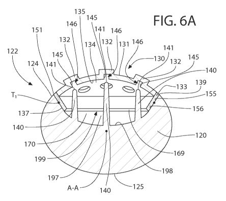
[0043] Referring to FIGS. 6A and 6B concurrently, the invention will be
further described. The
cross-sectional view depicted in FIGS. 6A and 6B is taken along line VI-VI of
FIG. 3. FIG. 6A
illustrates the grip component 130 when there is no force being applied to the
outer surface 131
of the resilient cover 134 of the grip component 130 such that the grip
component 130 (and more
specifically the resilient cover 134 of the grip component 130) is in its
natural state. Specifically,
in FIG. 6A the resilient cover 134 of the grip component 130 is in its biased
uncompressed state.
FIG. 6B illustrates the grip component 130 when a force F is being applied to
the outer surface
131 of the resilient cover 134 of the grip component 130. Upon the force F
being applied to the
outer surface 131 of the resilient cover 134 of the grip component 130, the
resilient cover 134 of
CA 02888940 2015-04-21
WO 2014/092673 PCT/US2012/068670
the grip component 130) becomes compressed into a compressed state. When the
resilient cover
134 is compressed, the resilient cover 134 contacts one or more of the
plurality of protuberances
140. Furthermore, upon release of the force F on the outer surface 131 of the
resilient cover 134
of the grip component 130, the resilient cover 134 of the grip component 130
is biased back into
the uncompressed state illustrated in FIG. 6A. Thus, the resilient cover 134
is self-biased into
the uncompressed state when no force is being applied to the outer surface 131
of the resilient
cover 134. In essence, the resilient cover 134 can be considered a spring-like
membrane.
[0044] The grip component 130 comprises the annular rim 133 and the first
resilient cover 134.
The outer surface 131 of the first resilient cover 134 is a dome-shaped outer
surface that
protrudes from the upper edge 139 of the annular rim 133. The upper edge 139
of the annular
rim 133 and the dome-shaped outer surface 131 of the first resilient cover 134
form a continuous,
uninterrupted and smooth surface with the front surface 124 of the handle
portion 120.
[0045] As discussed above, the annular rim 133 is formed of a rigid material
and the resilient
cover 134 is formed of a resilient material. In forming the grip component
130, the resilient
cover 134 is molded to the annular rim 133, such as by injection molding. In
the exemplified
embodiment, the resilient cover 134 is molded to top portions of the annular
rim 133 while
bottom portions of the annular rim 133 remain free of the resilient cover 134.
This is due to the
resilient cover 134 being formed as a thin resilient membrane having a
thickness that is less than
the height of the annular rim 133 (the height of the annular rim 133 extending
from bottom edge
169 of the annular rim 133 to the upper edge 139 of the annular rim 133). Of
course, the
invention is not to be so limited in all embodiments and in certain other
embodiments the
resilient cover 134 may cover the entire inner surface 136 of the annular rim
133.
[0046] In the exemplified embodiment, the outer surface 137 of the annular rim
133 is tapered.
Furthermore, the inner surface 155 of the handle portion 120 that defines the
socket 199
comprises a tapered sidewall 156. As used herein with regard to the sidewall
156, the term
tapered merely indicates that the wall is angled outwardly with distance from
the floor 198 of the
socket 199 so that the distance between opposing sides of the tapered sidewall
156 increases as
the tapered sidewall 156 extends further from the floor 198 of the socket 199
towards the open
top end 151. Tapering the sidewalls and the annular rim 133 increases the
stability of the grip
component 130 within the socket 199 by increasing the attachment between the
annular rim 133
of the grip component 130 and the inner surface 155 of the handle portion 120.
11
CA 02888940 2015-04-21
WO 2014/092673 PCT/US2012/068670
[0047] In the exemplified embodiment, the tapered outer surface 137 of the
annular rim 133 is in
abutment with the tapered sidewall 156 of the socket 199. Furthermore, in the
exemplified
embodiment the outer surface 137 of the annular rim 133 is thermally fused at
point T1, such as
by ultrasonic welding or otherwise, to the tapered sidewall 156 of the socket
199. An annular
interface is formed at the point T1 between the annular rim 133 and the
tapered sidewall 156 of
the socket 199, thereby forming a hermetic seal along the annular interface so
that an air-tight
pocket 170 is formed below the resilient cover 134, and more specifically
between the resilient
cover 134 and the floor 198 of the socket 199. Thus, the grip component 130 is
mounted within
the socket 199 and encloses the open top end 151 on the front surface 124 of
the handle portion
120. It should be appreciated that although the grip component 130 is
described as being
mounted within the socket 199, this includes instances in which at least a
portion of the grip
component 130 is disposed within the socket 199 and another portion of the
grip component 130
protrudes from the socket 199. In another embodiment, the annular rim 133
includes a full
perimeter energy director detail for the purpose of facilitating the
ultrasonic welding, to thereby join the
annular rim 133 to the body and create an air-tight pocket between the
resilient cover 134 and the rigid
handle.
[0048] As discussed above, in the exemplified embodiment the annular rim 133
of the grip
component 130 is thermally fused to the tapered sidewall 156 of the socket
199. However, the
invention is not to be so limited in all embodiments and in certain other
embodiments mounting
the grip component 130 within the socket 199 can be achieved via an
interference or tight fit
assembly, a coupling sleeve, threaded engagement, adhesion, fasteners or any
other known
techniques.
[0049] Furthermore, in certain embodiments whereby the grip component 130
includes the
annular rim 133 and the resilient cover 134, the handle portion 120 may
include a shoulder and
the annular rim 133 may include a flange such that the interaction between the
flange of the
annular rim 133 and the shoulder of the handle portion 120 facilitates
coupling of the grip
component 130 to the handle portion 120. In such an embodiment, after
positioning the grip
component 130 within the socket 199 as described above, the annular rim 133 is
thermally fused
to the handle portion 120 using techniques that have been described herein
above.
[0050] In certain embodiments the grip component 130 may not include an
annular rim such that
the resilient cover 134 of the grip component can be molded directly to the
handle portion 120.
12
CA 02888940 2015-04-21
WO 2014/092673 PCT/US2012/068670
Specifically, in certain embodiments the annular rim 133 can be omitted and
the resilient cover
134 can be connected directly to the inner surface 155 that defines the socket
199. Such direct
connection between the resilient cover 134 and the inner surface 155 can be
achieved by
injection molding the resilient cover 134 to the inner surface 155. In certain
such embodiments
the inner surface 155 may comprise a projection extending outwardly therefrom.
The projection
provides a mechanism for enhancing the attachment between the resilient cover
134 and the
handle portion 120. The projection can be an annular protuberance or one or
more isolated
projections extending from the inner surface 155 of the handle portion 120
inwardly towards the
socket 199. Furthermore, in still other embodiments the projection may be
altogether omitted
and the resilient cover 134 can be injection molded directly onto the flat,
smoother inner surface
155 of the handle portion 120. In other embodiments, the projection may be
replaced with a
recess or slot formed into the inner surface 155 of the handle portion 120 for
the resilient
material of the resilient cover 134 to flow into when molding the resilient
cover 134 to the
handle 120. Of course, in other embodiments the inner surface 155 of the
handle portion 120
may not include a projection or recess, and the resilient cover 134 of the
grip component 130
may be molded to the inner surface 155 of the handle portion 120 using
techniques known to
persons skilled in the art, including injection molding techniques described
herein above.
[0051] Thus, utilizing the above features, the grip component 130 can be
coupled to the handle
portion 120 without the use of the annular rim 133. Due to the lack of an
annular rim, the
resilient cover 134 of the grip component 130 can be mounted directly to the
handle portion 120.
In such embodiments, the projection or recess provides a surface for the
resilient cover 134 to
latch onto to prevent the resilient cover 134 of the grip component 130 from
being removed from
the socket 199 after being mounted thereto. The resilient cover 134 of the
grip component 130
can be mounted to the handle portion 120 by molding the resilient cover 134
directly to the
handle portion 120, such as by injection molding.
[0052] The resilient cover 134 is compressible into the air-tight pocket 170
in a direction
towards the floor 198 of the socket 199 and towards the longitudinal axis A-A
of the handle
portion 120. The resilient cover 134 is illustrated in the compressed state in
FIG. 6B, which
occurs as the result of the force F being applied to the outer surface 131 of
the resilient cover 134
of the grip component 130. After being compressed inwardly and upon release of
the force F on
13
CA 02888940 2015-04-21
WO 2014/092673 PCT/US2012/068670
the outer surface 131 of the resilient cover 134 of the grip component 130,
the resilient cover 134
biases back into the uncompressed state (illustrated in FIG. 6A).
[0053] The resilient cover 134 of the grip component 130 comprises an inner
surface 135.
Furthermore, as noted above the resilient cover 134 does not completely fill
in the empty space
within the socket 199. Rather, a space 197 (or air pocket) is formed between
the inner surface
135 of the resilient cover 134 of the grip component 130 and the floor 198 of
the socket 199.
The space 197 is a free volume (such as an air pocket) that is devoid of solid
material. The space
197 can be a gas-filled space (such as air-filled space) or can be a liquid-
filled space in certain
embodiments. Furthermore, in the exemplified embodiment the space 197 forms an
air-tight
pocket 170. The combination of the grip component 130 and the air-tight pocket
170 creates a
more comfortable grip for a user during toothbrushing. Furthermore the grip
component 130
uses less material than traditional grip components that completely fill the
socket 199, thereby
saving costs during manufacturing.
[0054] As discussed above, a plurality of protuberances 140 extend upwardly
from the floor 198
of the socket 199 in a direction towards the open top end 151. More
specifically, in the
exemplified embodiment the plurality of protuberances 140 extend upwardly in a
direction that is
transverse to the longitudinal axis A-A. Each of the protuberances 140 is
spaced and isolated
from each of the other protuberances 140. Thus, in the exemplified embodiment
there is a
plurality of isolated, separate and distinct protuberances 140 extending
upwardly from the floor
198 of the socket 199. As a result, the space 197 circumferentially surrounds
each of the
plurality of protuberances 140.
[0055] As noted above, each of the protuberances 140 has a columnar shape.
Furthermore, in
the exemplified embodiment the free ends 141 of the plurality of protuberances
140 are rounded
and the protuberances 140 are slightly tapered with distance from the floor
198 of the socket 199
towards the free ends 141. Of course, the invention is not to be so limited in
all embodiments
and in certain other embodiments the free ends 141 of the protuberances 140
can be pointed, flat,
or otherwise shaped. Furthermore, in other embodiments the protuberances 140
may have a
constant outer diameter rather than a tapered shape as illustrated. In still
other embodiments the
protuberances 140 may have a smaller width at the base portions near the floor
198 of the socket
199, and the width of the protuberances 140 may gradually increase from the
floor 198 of the
14
CA 02888940 2015-04-21
WO 2014/092673 PCT/US2012/068670
socket 199 to the free ends 141 of the protuberances. Such a structural
arrangement would make
the protuberances 140 more flexible.
[0056] In the exemplified embodiment, the free ends 141 of the protuberances
140 are located
beyond the open top end 155 of the socket 199. However, the invention is not
to be so limited in
all embodiments and in certain other embodiments the protuberances 140 may be
a height such
that the free ends 141 of the protuberances 140 do not extend beyond the open
top end 155 of the
socket 199. Despite the free ends 141 extending beyond the open top end 155 of
the socket, in
the exemplified embodiment when the resilient cover 134 is in the uncompressed
state (FIG.
6A), the inner surface 135 of the resilient cover 134 is spaced from the
protuberances 140, and
more specifically from the free ends 141 of the protuberances 140. This is due
to the dome-
shaped outer surface 131 of the resilient cover 134 of the grip component 130.
Thus, the inner
surface 135 of the resilient cover 134 is separated from the free ends 141 of
the protuberances
140 by a portion of the space 197.
[0057] Furthermore, in the exemplified embodiment, upon the force F being
applied to the outer
surface 131 of the resilient cover 134 of the grip component 130, the
resilient cover 134
compresses into the socket 199 and into the compressed state (FIG. 6B). When
the resilient
cover 134 is compressed into the compressed state, the inner surface 135 of
the resilient cover
134 of the grip component 130 contacts the free ends 141 of the protuberances
140. In the
exemplified embodiment, the protuberances 140 are arranged such that each of
the protuberances
140 is aligned with one of the tactile engagement elements 132 of the
resilient cover 134.
However, the invention is not to be so limited and the protuberances 140 need
not be aligned
with the tactile engagement elements 132 in all embodiments.
[0058] In the exemplified embodiment, when the resilient cover 134 is
compressed into the
compressed state, the free ends 141 of the protuberances 140 contact the inner
surface 135 of the
resilient cover 134 at the tactile engagement elements 132. In the exemplified
embodiment, each
of the tactile engagement elements 132 has an inner surface 145 that defines a
cavity 146 therein.
Furthermore, when the resilient cover 134 is compressed into the compressed
state, the free ends
141 of the protuberances 140 contact the resilient cover 134 such that the
free ends 141 of the
protuberances 140 are inserted into the cavities 146 of the tactile engagement
elements 132.
[0059] Of course, the invention is not to be so limited in all embodiments. In
certain
embodiments the tactile engagement elements 132 may be omitted and the inner
surface 135 of
CA 02888940 2015-04-21
WO 2014/092673 PCT/US2012/068670
the resilient cover 134 may be a smooth surface. Thus, in such embodiments
when the resilient
cover 134 is in the compressed state, the free ends 141 of the protuberances
140 merely contact
the smooth inner surface of the resilient cover 134. In still other
embodiments, the cavities 146
of the tactile engagement elements 132 may be filled with the resilient
material such that the free
ends 141 of the protuberances 140 can not enter into the cavities 145 when the
resilient cover
134 is in the compressed state. In still other embodiments, the protuberances
140 can be offset
from the cavities 145 of the tactile engagement elements 132. Regardless of
the particular
structure of the resilient cover 134 and the protuberances 140 and the
relative arrangement
therebetween, the free ends 141 of the protuberances 140 come into contact
with the inner
surface 135 of the resilient cover 134 when the resilient cover 134 is in the
compressed state.
[0060] Contact between the resilient cover 134 of the grip component 130 and
the protuberances
140 provides the user with a unique tactile sensation. Specifically, the user
can feel the
protuberances 140 through the resilient cover 134 when the resilient cover 134
contacts the
protuberances 140. This can be used to provide a warning to a user that he or
she is gripping the
oral care implement 100 with too much force, or it can be used to provide the
user with a
massage or other tactile sensation. In certain embodiments, the grip component
130 can be
designed so that the force F required to transition the resilient cover 134
into the compressed
state is a force that exceeds a predetermined threshold for toothbrushing.
Specifically, the
invention may be used such that when the user grips the handle portion 120 of
the elongated
body 101 with too great of a force, the user will be notified of this by the
resilient cover 134
achieving the compressed state and contacting the protuberances 140. In other
embodiments, the
contact between the resilient cover 134 and the protuberances 140 may achieve
a massaging
effect on a user's thumb such that the user desires to brush with a force F
sufficient to achieve
the compressed state in order to be rewarded with the massage or tactile
sensation. A
combination of the thickness of the resilient cover 134 and the height of the
protuberances 140
can be used to achieve the desired functionality of the grip component 130.
[0061] In the exemplified embodiment of FIGS. 6A and 6B, the free ends 141 of
the
protuberances 140 collectively form a reference plane having a curvature.
Specifically, a
reference plane connecting the free ends 141 of the protuberances 140 has an
arcuate curvature
that has a convex surface facing the resilient cover 134 and a concave surface
facing the floor
198 of the socket 199. In the exemplified embodiment, the curvature of the
reference plane that
16
CA 02888940 2015-04-21
WO 2014/092673 PCT/US2012/068670
connects the free ends 141 of the protuberances 140 corresponds to the
curvature of the inner
surface 135 of the resilient cover 134. Specifically, the curvature of the
reference plane has the
same radius of curvature as the curvature of the inner surface 135 of the
resilient cover 134. This
is achieved by forming a central one of the protuberances 140 to have a height
that is greater than
the protuberances 140 adjacent thereto so that the protuberance 140 located
below the highest
part of the dome of the resilient cover 134 has the greatest height. Of
course, the invention is not
to be limited by the curvature of the reference plane in all embodiments and
the relative heights
of the protuberances 140 can be other than that illustrated in FIGS. 6A and 6B
(see, for example,
FIG. 7 which will be discussed in more detail below).
[0062] Furthermore, in the exemplified embodiment each of the protuberances
140 is integrally
formed with the handle portion 124 of the elongated body 101. Thus, in the
exemplified
embodiment the protuberances 140 are formed of a rigid plastic material, such
as for example
without limitation polymers and copolymers of ethylene, propylene, butadiene,
vinyl compounds
and polyesters such as polyethylene terephthalate. The invention is not to be
so limited in all
embodiments and in certain other embodiments the protuberances 140 can be
formed of a
material that is different than the material of the handle portion 120. For
example, the
protuberances 140 can be formed of a resilient material, such as a
thermoplastic elastomer. In
such embodiments, the resilient material may be the same as the material of
the resilient cover
134, or the resilient material may have a greater hardness than the hardness
of the material of the
resilient cover 134 to prevent the protuberances 140 from collapsing upon
contact by with the
resilient cover 134. In still other embodiments, the protuberances 140 may be
formed with a
core formed from a rigid material and a shell formed from a resilient material
to provide a
combination of durability and comfort. In further embodiments, some of the
protuberances 140
can be integrally formed with the elongated body 101 out of the rigid material
and others of the
protuberances 140 can be separately formed from the elongated body 101 out of
a resilient
material.
[0063] In certain embodiments, the resilient cover 134 is formed of a
transparent or translucent
material. In such embodiments, the protuberances 140 are visible through the
resilient cover
134. In this manner, a user viewing the oral care implement 100 can see the
protuberances 140
through the resilient cover 134 prior to and during use of the oral care
implement 100. This will
provide the oral care implement 100 with an enhanced aesthetic and serve as an
informative
17
CA 02888940 2015-04-21
WO 2014/092673 PCT/US2012/068670
feature by enabling a consumer or potential purchaser to see the massaging or
pressure warning
feature prior to purchase thereof
[0064] Turning now to FIGS. 7A and 7B concurrently, an alternative embodiment
of a thumb-
grip section 122A of the oral care implement 100 will be described. The thumb-
grip section
122A is similar to the thumb-grip section 122 described above and depicted in
FIGS. 6A and 6B.
Thus, only the structural components of the thumb-grip section 122A that are
different than the
thumb-grip section 122 will be discussed herein below with the understanding
that the
description above with regard to FIGS. 1-6B applies to all other structural
components.
Furthermore, the components of the thumb-grip section 122A will have the same
reference
numerals as similar components from the thumb-grip section 122 except that the
suffix "A" will
be used. It will be understood that features that are not described below are
the same as its
similarly numbered feature described above. Specifically, the grip component
130A is
substantially similar to the grip component 130 described above. Thus, a
detailed description of
the grip component 130A will be not provided below, with the understanding
that the description
above applies.
[0065] In the embodiment exemplified in FIGS. 7A and 7B, a plurality of
protuberances 140A
protrude upwardly from the floor 198A of the socket 199A. Furthermore, FIG. 7A
illustrates the
resilient cover 134A of the grip component 130A in a biased uncompressed
state, and FIG. 7B
illustrates the resilient cover 134A of the grip component 130A in a
compressed state (which is
achieved by application of the force F onto the outer surface 131A of the
resilient cover 134A).
The difference between the embodiment exemplified in FIGS. 7A and 7B and the
embodiment
exemplified in FIGS. 6A and 6B is the relative height of the protuberances
140A. Specifically,
in FIGS. 7A and 7B, the protuberances 140A include a first set of
protuberances 148A and a
second set of protuberances 149A. In the exemplified embodiment, the
protuberances 140A of
the second set of protuberances 149A are positioned in between the
protuberances 140A of the
first set of protuberances 148A.
[0066] In FIG. 7A, wherein the resilient cover 134A is in the biased and
uncompressed state
(i.e., no force is being applied to the outer surface 131A of the resilient
cover 134A), the free
ends 141A of the protuberances 140A of the first set of protuberances 148A are
in contact with
the inner surface 135A of the resilient cover 134A and the free ends 141A of
the protuberances
140A of the second set of protuberances 149A are spaced from the inner surface
135A of the
18
CA 02888940 2015-04-21
WO 2014/092673 PCT/US2012/068670
resilient cover 134A. Thus, in the embodiment exemplified in FIG. 7A, a user
will feel the
sensation of the protuberances 140A of the first set of protuberances 148A
even without
compressing the resilient cover 134A into the compressed state. However, as
illustrated in FIG.
7B, a force F applied to the outer surface 131A of the resilient cover 134A
will compress the
portions of the resilient cover 134A that are spaced from the protuberances
140A (such as the
portions aligned with and above the protuberances 140A of the second set of
protuberances
149A) until the inner surface 131A of the resilient cover 134A contacts those
protuberances
140A. Thus, the protuberances 140A can be used to limit or otherwise control
the areas of
compressibility of the resilient cover 134A, which will affect the resulting
tactile sensation felt
by a user during toothbrushing.
[0067] Of course, the invention is not to be particularly limited by the
relative heights of the
protuberances 140, 140A as illustrated in the figures provided herewith. The
protuberances 140,
140A can take on many different configurations to achieve many different
tactile experiences
and pressure sensor warnings as desired. Thus, the invention is not to be
particularly limited by
the configuration, pattern, arrangement, size, shape and/or number of the
protuberances 140,
140A unless so specified in the claims.
[0068] Referring now to FIGS. 8-11 concurrently, a method of manufacturing an
oral care
implement 500 having the features discussed herein will be described. In
manufacturing the oral
care implement 500, first an elongated body 501 comprising a handle portion
520 and a head
portion 510 is formed from a first material, the first material being a hard
plastic. The elongated
body 501 is formed so as to have a socket 599 formed into the handle portion
520. The socket
599 has a floor 598 and an open top end 551. Forming the elongated body 501
includes forming
a first mold cavity and injecting a molten form of the first material into the
first mold cavity, the
first mold cavity having a shape that corresponds to the shape of the
elongated body 501. After
injecting the molten form of the first material into the first mold cavity,
the molten form of the
first material is allowed to cool within the first mold cavity, thereby
forming the elongated body
501 having the socket 599 formed therein.
[0069] Next, at least one protuberance 540 is formed so as to extend upwardly
from the floor
598 of the socket 599. In certain embodiments, the protuberances 540 can be
formed integrally
with the elongated body 501 such that the first mold cavity includes shaping
that corresponds to
the shape of the protuberances 540. In such embodiments, the formation of the
elongated body
19
CA 02888940 2015-04-21
WO 2014/092673 PCT/US2012/068670
501 and the protuberances 540 are achieved concurrently in a single injection
molding step. In
other embodiments, the protuberances 540 can be separately formed from and
later connected to
the floor 598 of the socket 599 by any means known in the art. For example,
the protuberances
540 can be formed from a resilient material, such as an injection molded
thermoplastic. In other
embodiments the protuberances 540 can be formed of a rigid material that is
similar to the
material of the elongated body 501, but the protuberances 540 can simply be
formed separately
from the elongated body 501 and later connected thereto.
[0070] Next, a grip component 530 is formed. In certain embodiments, the grip
component 530
may include only a cover 534 formed of a second material. However, in other
embodiments the
grip component 530 comprises an annular rim 533 having a central opening 538
and the cover
534. The annular rim 533 is formed of a third material. In certain
embodiments, the first
material that forms the elongated body 501 is the same as the third material
that forms the
annular rim 533. However, the invention is not to be so limited in all
embodiments.
Nonetheless, it is preferable that both the first and third materials are
rigid materials, such as has
been described herein above.
[0071] Forming the annular rim 533 includes forming a second mold cavity and
injecting a
molten form of the third material into the second mold cavity, the second mold
cavity having a
shape that corresponds to the shape of the annular rim 533. Next, the molten
form of the third
material within the second mold is allowed to cool, thereby forming the
annular rim 533. After
forming the annular rim 533, the cover 534 is mounted to the annular rim 533
so as to cover the
opening 538 in the annular ring 533. The cover 534 is formed of a second
material. In certain
embodiments, the second material is more resilient than the first and third
materials, and more
specifically the second material can be a thermoplastic elastomer. To form the
cover 534 and
mold the cover 534 onto the annular ring 533, a third mold cavity is formed at
the central
opening 538 of the annular rim 533 and a molten form of the second material is
injected into the
third mold cavity into contact with the annular rim 533. The third mold cavity
has a shape that
corresponds to the first cover 534, including any tactile engagement elements
532 that are
extending from the first cover 534. Finally, the molten form of the second
material is allowed to
cool within the third mold cavity, thereby forming the grip component 530 in
which the cover
534 is molded to the annular rim 533. In the exemplified embodiments, the
first and third
CA 02888940 2015-04-21
WO 2014/092673 PCT/US2012/068670
materials are rigid materials and the third material is a resilient material.
Figure 10 illustrates the
first grip component 530 having the cover 534 molded onto the annular rim 533.
[0072] Although the invention has been described herein with the grip
component 530 including
the annular rim 533 and the cover 534, the invention is not to be so limited
in all embodiments.
In certain embodiments, the grip component 530 may include only a cover 534
formed of the
second material. In such embodiments, the annular rim 533 is omitted.
[0073] After forming the elongated body 501 and the first grip component 530,
the first grip
component 530 is mounted within the socket 599 of the handle portion 520 of
the elongated body
501. This includes positioning the grip component 530 within the socket 599 of
the handle
portion 520 and thermally fusing the annular rim 533 of the grip component 530
to the handle
portion 520, thereby securing the grip component 530 to the handle portion
520. Of course, as
has been discussed above the grip component 530 may otherwise be secured to
the handle
portion 520, such as be utilizing an interference fit, adhesion, fasteners or
the like. Further still,
in embodiments that omit the annular rim 533, the cover 534 may be injection
molded directly
into the socket 599 to enclose the open top end 551 of the socket 599. Upon
mounting the cover
534 to the handle portion 520 to enclose the open top end 551 of the socket
599, an inner surface
of the cover 534 is separated from the floor 598 of the socket 599 by a space.
[0074] Upon securing the annular rim 533 to the handle portion 520 (or
otherwise securing the
grip component 530 to the handle portion 520), the grip component 530 covers
and encloses the
open top end 551 of the socket 599. As a result, an air-tight pocket is formed
beneath the cover
534 of the grip component 530. This provides a comfortable gripping component
for a user
during use of the oral care implement 500.
[0075] As used throughout, ranges are used as shorthand for describing each
and every value
that is within the range. Any value within the range can be selected as the
terminus of the range.
In addition, all references cited herein are hereby incorporated by referenced
in their entireties.
In the event of a conflict in a definition in the present disclosure and that
of a cited reference, the
present disclosure controls.
[0076] While the invention has been described with respect to specific
examples including
presently preferred modes of carrying out the invention, those skilled in the
art will appreciate
that there are numerous variations and permutations of the above described
systems and
techniques. It is to be understood that other embodiments may be utilized and
structural and
21
CA 02888940 2015-04-21
WO 2014/092673 PCT/US2012/068670
functional modifications may be made without departing from the scope of the
present invention.
Thus, the spirit and scope of the invention should be construed broadly as set
forth in the
appended claims.
22