Note: Descriptions are shown in the official language in which they were submitted.
CA 02889201 2016-10-05
Title: Surface Excitation Ranging System for SAGD Application
Field of the Invention
The invention relates to wellbore drilling operations, and more particularly
to methods and
systems for tracking the drilling of multiple wellbores relative to one
another. Most
particularly, the invention relates to methods and systems for determining the
relative
location of a reference wellbore from a wellbore being drilled utilizing
optimized placement
of emitter electrodes and return electrodes to enhance magnetic ranging.
Background of the Invention
As easy-to-access and easy-to-produce hydrocarbon resources are depleted,
there is an
increased demand for more advanced recovery procedures. One such procedure is
steam
assisted gravity drainage (SAGD), a procedure that utilizes steam in
conjunction with two
spaced apart wellbores. Specifically, SAGD addresses the mobility problem of
heavy oil in a
formation through the injection of high pressure, high temperature steam into
the formation.
This high pressure, high temperature steam reduces the viscosity of the heavy
oil in order to
enhance extraction. The injection of steam into the formation occurs from a
first wellbore
(injector) that is drilled above and parallel to a second wellbore (producer).
As the viscosity
of the heavy oil in the formation around the first wellbore is reduced, the
heavy oil drains into
the lower second wellbore, from which the oil is extracted. Typically, the two
wellbores are
drilled at a distance of only a few meters from one other. The placement of
the injector
wellbore needs to be achieved with very small margin in distance. If the
injector wellbore is
positioned too close to the producer wellbore, the producing wellbore would be
exposed to
very high pressure and temperature. If the injector wellbore is positioned too
far from the
producer wellbore, the efficiency of the SAGD process is reduced. In order to
assist in
ensuring that the second wellbore is drilled and positioned as
desired relative to the first wellbore, a survey of the two wellbores in the
formation is often
conducted. These surveying techniques are traditionally referred to as
"ranging".
Electromagnetic (EM) systems and methods are commonly employed in ranging to
determine
direction and distance between two wellbores. In EM ranging systems, an
elongated conductive pipe
string, such as the wellbore casing, is disposed in one of the wellbores. This
wellbore is typically
referred to as the "target" wellbore and usually represents the SAGD injector
wellbore. In any event,
a current is applied to the target wellbore conductive pipe string by a low-
frequency current source.
Currents flow along the wellbore casing and leak into the formation. The
currents result in an EM
field around the target wellbore. The EM fields from the currents on the
target wellbore casing are
measured using an electromagnetic field sensor system disposed in the other
wellbore, which is
typically the wellbore in the process of being drilled. This second wellbore
usually represents the
SAGD producer wellbore. The measured magnetic field can then be utilized to
determine distance,
direction and angle between two wellbores. Ranging systems in which a current
is injected into the
target wellbore in order to induce a magnetic field are referred to as
"active" ranging systems.
One solution that has been employed in EM ranging is to use ranging devices to
directly sense and
measure the distance between two wells as the latter wellbore is drilled. Two
wellbore-known
commercial approaches that employ equipment in both wells (injector and
producer) are based either
on rotating magnets or magnetic guidance techniques. However, these approaches
are undesirable in
that they require two separate and different teams to manage the equipment in
each wellbore,
namely, a wireline team at the producer wellbore and a logging while drilling
team at the injector
wellbore, which is not cost effective. One prior art approach utilizes
equipment in only a single
wellbore (the injector wellbore) to transmit a current to a target wellbore
(the producer wellbore),
after which an absolute magnetic field measurement is used to calculate
distance. One significant
drawback to this method is that the approach tends to yield very unreliable
results because of the
placement of the emitter and return electrodes relative to one another and
relative to a magnetometer.
Summary
In one aspect, there is provided a wellbore ranging system comprising: a first
wellbore having a first
end proximate a wellhead at the surface of a formation and a second, distal
end disposed along a
portion of a reference axis coaxially extensive with at least a portion of the
first wellbore, the
reference axis having a reference point thereon, wherein an elongated
conductive member is
disposed within a portion of the first wellbore; a current injection system
comprising a source of
CA 2839201 2017-07-18
2
alternating current at the surface, an emitter electrode, and a return
electrode, wherein the emitter
electrode is spaced apart from the wellhead and the return electrode is
positioned at a location remote
from the emitter electrode; a second wellbore extending from the surface; and
an EM sensor
disposed within the second wellbore.
Brief Description of the Drawings
FIG. 1 illustrates surface-excitation of a target wellbore in a single
wellbore ranging system
FIG. 2 illustrates a well-head and pipe excitation configurations for the
systems of FIG. I.
CA 2839201 2017-07-18
2a
CA 02889201 2015-04-21
WO 2014/089402 PCT/US2013/073521
FIG. 3a illustrates an embodiment of the invention where a source emits a
current into the formation
proximate a target wellbore and the current returns to a ground spaced apart
from the emitter.
FIG. 3b illustrates an embodiment of the invention where a source delivers a
current to a target wellbore
and utilizes a grounded return in a separate wellbore spaced apart from the
target and injector wellbores.
FIG. 3c illustrates an embodiment of the invention where a source delivers a
current to a target wellbore
and utilizes a grounded return in the injector wellbore.
FIG. 4a illustrates an embodiment of the invention where a source, spaced
apart from a target wellhead,
emits a current into a shallow formation and the current returns to a ground
spaced apart from the
emitter.
FIG. 4b illustrates an embodiment of the invention where a source is provided
with an emitter
positioned downhole on a twisted wire pair for delivery of a current to a
target pipe string and a
grounded return in positioned farther downhole in the target wellbore.
FIG. 4c illustrates an embodiment of the invention where a source is provided
with an emitter positioned
downhole on a twisted wire pair for delivery of a current to an elongated wire
loop positioned within the
target wellbore.
FIG. 5 illustrates the magnetic gradient-based measurement principle of a
gradient-based wellbore
ranging system.
FIG. 6 illustrates 3-, 4- and 8-dipole arrangements for a gradient-based
wellbore ranging system.
FIG. 7 is a graph illustrating the uncertainty in absolute measurement vs.
gradient measurement of
magnetic fields.
FIG. 8 illustrates a method to measure distance using a gradient-based
wellbore ranging system.
3
CA 02889201 2015-04-21
WO 2014/089402 PCT/US2013/073521
FIG. 9 is a flow chart of a ranging method of a gradient-based wellbore
ranging system utilizing
magnetic field gradient.
FIG. 10 is a flow chart of a ranging method for wellbores utilizing optimized
placement of emitter and
return electrodes to enhance system performance.
Detailed Description
The foregoing disclosure may repeat reference numerals and/or letters in the
various examples. This
repetition is for the purpose of simplicity and clarity and does not in itself
dictate a relationship between
the various embodiments and/or configurations discussed. Further, spatially
relative terms, such as
"beneath," "below," "lower," "above," "upper," "uphole," "downhole,"
"upstream," "downstream," and
the like, may be used herein for ease of description to describe one element
or feature's relationship to
another element(s) or feature(s) as illustrated in the figures. The spatially
relative terms are intended to
encompass different orientations of the apparatus in use or operation in
addition to the orientation
depicted in the figures. For example, if the apparatus in the figures is
turned over, elements described as
being "below" or "beneath" other elements or features would then be oriented
"above" the other
elements or features. Thus, the exemplary term "below" can encompass both an
orientation of above
and below. The apparatus may be otherwise oriented (rotated 90 degrees or at
other orientations) and
the spatially relative descriptors used herein may likewise be interpreted
accordingly.
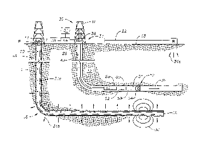
Referring initially to FIGS. I a and lb, a first wellbore 10 extends from a
wellhead 11 into a formation
12 from the surface 13 of the formation. Disposed within wellbore 10 along at
least a portion of its
length is an elongated conductive member 14, which is generally oriented
within wellbore 10 to be
axially aligned therewith. Wellbore 10 may be cased or uncased. To the extent
wellbore 10 is cased, in
some embodiments, conductive member 14 may be a casing or liner disposed
within wellbore 10. For
either cased or uncased wellbores, in some embodiments, conductive member 14
may be a pipe string,
tool string, tubing, electrical wire or other conductive body disposed in
first wellbore 10. In any event,
the intent is to provide a path for current flow along a substantial length of
a reference wellbore, and any
conduction path that serves this purpose can be used. Moreover, conductive
member 14 is generally
disposed within wellbore 10 to radiate a magnetic field radially outward from
wellbore 10.
4
CA 02889201 2015-04-21
WO 2014/089402 PCT/US2013/073521
In some embodiments, first wellbore 10 may include a vertical section 16 and a
directional section 18.
The directional section 18 is drilled from the vertical section 16 along a
desired azimuthal path and a
desired inclination path.
A second wellbore 28 shown in the process of being drilled. A drilling system
30 is generally shown
associated therewith. Drilling system 30 may include a drilling platform 32
positioned over formation
12, and a wellhead installation 34, including blowout preventers 36. Platform
32 may be disposed for
raising and lowering a conveyance mechanism 48 within second wellbore 28.
Conveyance mechanism
48 may be tubing, a pipe string such as a drill string, or a cable, such as a
wireline, slickline or the like,
depending on the operation being conducted within second wellbore 28.
Carried by conveyance mechanism 48 in second wellbore 28 is an electromagnetic
("EM") sensor 51.
In some embodiments, the EM sensor 51 can measure at least one component of a
magnetic field or the
gradient of a magnetic field. In some embodiments, the EM sensor 51 can
measure at least one
component of an electric field or the gradient of an electric field. In some
embodiments, EM sensor 51
includes at least a magnetic gradient sensor or magnetic gradiometer
(receiver).
A current injection system for driving current to conductive member 14
includes at least one pair of
electrodes, namely an emitter "E" electrode and a return "R". Emitter
electrode E and return electrode
R, together with the current injection system generally form a wellbore
ranging system. The current
injection system, namely emitter electrode E and return electrode R, injects
alternating currents (AC)
into formation 12 which currents travel to and then along conductive member 14
in first wellbore 10.
EM sensor 51 is disposed within the second wellbore 28 to sense the magnetic
fields due to these AC
currents on the conductive member 14. In any event, distance and direction to
target can be calculated
by analyzing the measured magnetic fields. In some embodiments where EM sensor
51 comprises a
gradiometer, the gradient of a magnetic field may be measured and utilized to
determine the range
between the wellbores.
To the extent drilling system 30 is being utilized to actively drill second
wellbore 28, EM sensor 51 may
be part of the bottom-hole-assembly (BHA) 52 of a drilling system. In such
embodiments, conveyance
mechanism 48 may be a tubing or drill string, having a BHA 52 attached to the
end of string 48. BHA
52 includes a drill bit 54. In one or more embodiments, EM sensor 51 can be
positioned proximate or
adjacent drill bit 54. BHA may also include a power module 56, such as a mud
motor, a steering
CA 02889201 2015-04-21
WO 2014/089402 PCT/US2013/073521
module 58, a control module 60, and other sensors and instrumentation modules
62. As will be
appreciated by persons of skill in the art, the BHA 52 illustrated in FIGS. la
and lb may be a
measurement-while-drilling or logging-while-drilling system in which EM
ranging can be utilized to
guide drill bit 54 while a drill string is deployed in wellbore 28.
The current injection system also includes either a voltage controlled or
current controlled transmitter
38, and in some embodiments, alternates as very low frequencies in the order
of 0.02-250 Hz to generate
the current injected by emitter electrode E. Transmitter 38 may be locally
positioned relative to emitter
electrode E. or positioned at a location removed from emitter electrode E in
electrical contact with
electrode E via conductive wiring. Likewise, power and communications to EM
sensor 51 may be
carried locally by appropriate modules 56-62 or may be transmitted via
conveyance system 48.
The mud motor module 56 is driven by the drilling fluid flow, and in turn it
drives the drill bit 54 to
extend the second wellbore 28 along a desired path 32. Desired path 32 is
shown as running parallel to
the horizontal portion of wellbore 10 because in many cases, such as steam-
assisted gravity drainage
(SAGD) or coal bed degasification, it is desirable to drill a series of
closely-spaced parallel wells. Mud
motor module 56 may provide power to the current injection system and/or the
EM sensor 51.
Steering module 58 enables the wellbore 28 to be extended in a desired
direction. Many suitable
steering mechanisms are well known, e.g., steering vanes, "bent sub"
assemblies, and rotary steerable
systems. The steering mechanism configuration can be set and adjusted by
commands from a control
system 64 at the surface, such as a logging truck or other control skid.
Alternatively, control module 60
can be programmed with a desired route, and it can adjust the steering
mechanism as needed to direct
the wellbore along the desired path.
While the current injection system and EM sensor 51 as described herein are
illustrated with respect to
land-based drilling systems, the disclosure also includes use with offshore
and marine drilling system.
Moreover, deployment of the current injection system and EM sensor 51 is not
limited to any particular
orientation of the first and second wellbores. As depicted in FIG. 1, first
and second wellbores 10, 28,
respectively are substantially horizontal wellbores. In such case, current
injection system and EM
sensor 51 may be particularly useful in ranging for SAGD operations.
Alternatively, first and second
wellbores 10, 28, respectively are substantially vertical wellbores. Thus,
current injection system and
6
CA 02889201 2015-04-21
WO 2014/089402 PCT/US2013/073521
EM sensor 51 may be used in drilling relief wells or intersecting wells, such
as when it is desirable to
establish direct fluid communication between two wells. This may be
particularly useful in wellbore
intervention operations, for example.
In any event, a control system 31 may also be deployed to control drilling
system 30 based on EM
ranging utilizing current injection system and EM sensor 51.
Thus, a wellbore ranging system consists of two parts: (i) a source of
current, namely a current injection
system comprised of an emitter electrode E and return electrode R spaced apart
from emitter electrode
E, the separation of the emitter electrode E and the return electrode R
selected to drive alternating
currents (AC) from emitter electrode E, along conductive member 14 in first
wellbore 10 and back to
return electrode R, and (ii) an EM sensor 51, namely a magnetic gradient
sensor or magnetic
gradiometer or a magnetometer, positioned within the investigative or second
wellbore and disposed to
sense magnetic fields or the gradient magnetic fields due to these AC currents
on the conductive
member 14. While the system and method of the invention are not limited to a
particular magnetic field
measurement, in one embodiment, either the absolute magnetic field or the
gradient is measured, while
in another embodiment, both are measured. Distance and direction to target can
be calculated by
analyzing the measured magnetic fields. The emitter electrode E is positioned
at a point near the surface
or at a fixed point in the target wellbore. The return electrode R is
positioned at or near the surface or
within the formation, but in either case, spaced apart from the emitter
electrode E so that currents
flowing from emitter electrode E to return electrode R encounter or are
otherwise first driven to the
conductive member 14 within first wellbore 10.
FIG. la illustrates a current injection system where the emitter electrode E
is located at the surface 13,
proximate or adjacent first wellbore 10, while return electrode R is
positioned along the surface 13 at a
distance spaced apart from emitter electrode R, as well as first wellbore 10.
In some embodiments,
emitter electrode E is electrically attached to wellhead 11 to facilitate
conduction of current to
conductive member 14. An insulated conductive wire 22 joins return electrode R
and emitter electrode
E to complete an electrical circuit. As such, current injected at emitter
electrode E travels down and
along conductive member 14, as illustrated by current lines 34a. While a
portion of the current will leak
into formation 12 as shown by current lines 34b, most of current 34a will
travel along conductive
member 14, thereby resulting in an electromagnetic field 36 emanating from
conductive member 14.
Return electrode R is positioned on the surface so that current 34a that
travels along conductive member
7
CA 02889201 2015-04-21
WO 2014/089402 PCT/US2013/073521
will then pass through the formation 12 back to return electrode R as shown by
current lines 34c, thus
completing the circuit. Based on the location of wellbore 10, current within
wellbore 10 can be
optimized by adjusting the relative placement of the emitter electrode E and
the return electrode R. In
some embodiments, as illustrated in FIG. la, the return electrode R is
positioned on the surface 13
proximate or adjacent to or past the distal end 20 of the first wellbore 10 in
order to ensure that the
current 34a will travel along the conductive member 14 disposed therein before
passing through the
formation 12 back to the return electrode R.
FIG. lb illustrates a current injection system where the emitter electrode E
is located within first
wellbore 10, while return electrode R is positioned along the surface 13 at a
distance spaced apart from
emitter electrode R, as well as first wellbore 10. In some embodiments,
emitter electrode E is
electrically attached to conductive member 14 to facilitate conduction of
current to conductive member
14. An insulated conductive wire 22 joins return electrode R and emitter
electrode E to complete an
electrical circuit. As such, current injected at emitter electrode E travels
along conductive member 14,
as illustrated by current lines 34a. While a portion of the current will leak
into formation 12 as shown
by current lines 34b, most of current 34a will travel along conductive member
14, thereby resulting in
an electromagnetic field 36 emanating from conductive member 14. Return
electrode R is positioned on
the surface so that current 34a that travels along conductive member will then
pass through the
formation 12 back to return electrode R as shown by current lines 34c, thus
completing the circuit.
Based on the location of wellbore 10, current within wellbore 10 can be
optimized by adjusting the
relative placement of the emitter electrode E and the return electrode R. In
some embodiments, as
illustrated in FIG. 1 b, the return electrode R is positioned on the surface
13 proximate or adjacent to or
past the distal end 20 of the first wellbore 10 in order to ensure that the
current 34a will travel along the
conductive member 14 disposed therein before passing through the formation 12
back to the return
electrode R.
In FIG. 2a, the emitter electrode E of FIG. 1 a is illustrated in more detail.
Specifically, a transmitter 38
located at the surface 13 generates a current 34 on emitter electrode E that
is connected to the first
wellbore 10 via an insulated cable 25 that is directly clamped or connected to
the wellhead 11, which is
in direct electrical contact with the conductive member 14.
In FIG. 2b, the emitter electrode E of FIG. 2b is illustrated in more detail.
Specifically, a transmitter 38
located at the surface 13 generates a current 34 that is delivered via an
insulated cable 25 to an emitter
8
CA 02889201 2015-04-21
WO 2014/089402 PCT/US2013/073521
electrode E that is deployed downhole in the first wellbore 10 and is
electrically attached to conductive
member 14, which may be in the vicinity of the area that is targeted for SAGD
drilling. In some
embodiments, cable 25 may be shielded to minimize interference with the
magnetic field generated by
the conductive member 14.
In the embodiments of both FIGS 2a and 2b, currents 34a travelling on the
conductive member 14
gradually leak into the proximate or adjacent formation 12 (see FIGS. 1 a and
1 b) and follow an
exponential decay provided that they are far from the ends of the conductive
member 14. It is known
that such current excitation can reach distances as large as 10000 feet and
beyond, which is desirable for
the SAGD application of the invention. In order to minimize resistance of the
load that is connected to
the transmitter 38, contact may be designed to reduce contact resistance as
much as possible. For
example, in the case of downhole excitation from the wellhead (FIGS. 1 a and
2a), a mechanical clamp
may be used. In the case of downhole excitation from a point within the target
wellbore, an elongated
conductor may be positioned on the wellbore floor and urged against the
wellbore, such as by gravity, to
enhance contact with the formation.
FIG. 3a illustrates an embodiment similar to FIG. la, but where emitter
electrode E is not in direct
electrical contact with conductive member 14 or wellhead 11. Rather, emitter
electrode E injects current
via the emitter electrode E into the formation 12 proximate or adjacent the
wellhead 11. Emitter
electrode E is positioned close enough to the wellhead 11 that current will
flow through the formation
12 to the target wellbore 10 and conductive member 12. Persons or ordinary
skill in the art will
appreciate that in this configuration, the return electrode R must be
positioned a distance sufficiently far
away from the emitter electrode E so that the current 34 will flow first to
the conductive member 14 of
first wellbore 10 and then to the return electrode R, as opposed flowing
directly to the return electrode
E.
As stated above, the placement or position of the return electrode R for the
current injection system can
be selected to optimize performance of the wellbore ranging system. In certain
embodiments, as
illustrated in certain of FIGS. 3 and 4, a reference axis YY can be selected
and utilized to position the
return electrode R. The reference axis YY may be selected to pass through the
end 20 of the first
wellbore 10, extending out into the formation 12, and around which the end
portion of the wellbore is
defined. A reference point 37 along the reference axis YY is selected and the
position of the return
electrode R is then selected to minimize the distance "D" between the
reference point 37 and the return
9
CA 02889201 2015-04-21
WO 2014/089402 PCT/US2013/073521
electrode R. In this case, optimization would include generating the strongest
magnetic field possible
from the conductive member 14 in the area being measured by the EM sensor 51
of the second wellbore
28.
FIG. 3b illustrates an embodiment similar to FIG. 3a, but where return
electrode R is not on the surface
13. Rather, return electrode R is positioned within formation 12.
Specifically, return electrode R is
lowered, on a wireline, slickline or other cable, down into a third wellbore
29 extending from surface 13
into formation 12. As shown, insulated conductive wire 22 joins return
electrode R and emitter
electrode E to complete an electrical circuit. Alternatively, the third
wellbore 29 may include a pipe
string, such as casing or a drill string (not shown) in contact with the
formation 12, that is electrically
connected to return electrode R positioned at the surface 13 of the third
wellbore 29. In these
embodiments, it will be appreciated that reference point 37, and hence return
electrode R, need not be
positioned as far away from the end 20 of first wellbore 10 as in earlier
described embodiments because
the conductive member 14 of first wellbore 10 is more directly positioned
between the physical position
of emitter electrode E and return electrode R such that the current 34 is more
likely to travel along
conductive member 14 directly to return electrode R as opposed directly
traveling through the formation
12 between emitter electrode E and return electrode R.
FIG. 3c illustrates an embodiment similar to FIG. 3b, but where the return
electrode R in the formation
12 is positioned within second wellbore 28. Specifically, return electrode R
can be carried by the
conveyance mechanism 48 that also carries EM sensor 51. Alternatively, return
electrode R may be
lowered within conveyance mechanism 48 into second wellbore 28 on a cable,
such as a wireline. Other
modules 56, 58, 60, 62 may also be carried by conveyance mechanism 48 as
described above. The
emitter electrode E may be attached directly to the first wellbore 10 (as
described in FIG. la) or
separated from the first wellbore 10 (as described in FIG. 3a). Insulated wire
22 extends between
emitter electrode E and return electrode R to complete a circuit. In certain
embodiments, the
conveyance mechanism 48 includes one or more insulators or gap subs G deployed
along conveyance
mechanism 48 to insulate the return electrodes R from the EM sensor 51, and in
particular, to inhibit
current 34c from traveling along conveyance mechanism 48 from return electrode
R to EM sensor 51..
As used herein, "gap sub" means an insulator such as a gap in conductive
portions of a pipe string or an
insulating portion of a pipe or an insulator sub or any other non-conductive
device deployed to inhibit
current flow along the drill string.
CA 02889201 2015-04-21
WO 2014/089402 PCT/US2013/073521
Turning to FIG. 4a, an embodiment of a wellbore ranging system is illustrated
where an emitter
electrode E is positioned on the surface 13 of the formation 12 above the
first wellbore 10, while the
return electrode R is positioned on the surface of the formation 12 at a
distance spaced apart from
emitter electrode E. A reference axis YY can be selected and utilized to
position the return electrode R.
The reference axis YY may be selected to pass through the end 20 of the first
wellbore 10, extending out
into the formation 12, and around which the end portion of the wellbore is
defined. A reference point 37
along the reference axis YY is selected and the position of the return
electrode R is then selected to
minimize the distance "D" between the reference point 37 and the return
electrode R. In this case,
optimization would include generating the strongest magnetic field possible
from the conductive
member 14 in the area being measured by the EM sensor 51 of the second
wellbore 28. As such, current
34 injected into the ground by emitter electrode E will travel to first
wellbore 10, then along conductive
member 14 and finally, back through the formation to return electrode R. As
shown, an insulated wire
22 extending between emitter electrode E and return electrode R completes the
circuit. It will be
appreciated that due to loss of current in the formation, this particular
embodiment would be most
desirable in ranging instances where the target wellbore 10 is positioned in
the formation at a relatively
shallow depth, such as for instance, at a depth of 30 feet or less, and in
some embodiments, at a depth of
less than 20 feet. In general, "spaced apart" means there is no
uninterrupted electrical connection
through an electric conductor such as copper or other metals.
FIG. 4b illustrates a current injection system where the emitter electrode E
and the return electrode R
are both located downhole within first wellbore 10, but spaced apart from one
another. Emitter
electrode E is deployed on a twisted wire pair 39 for delivery of a current to
conductive member 14.
Return electrode R is grounded further downhole. In this case, the current
travels axially along the
target pipe string and a magnetic field is generated from the pipe string.
Current 34 injected at emitter
electrode E travels along conductive member 14, as illustrated by current
lines 34a. While a portion of
the current will leak into formation 12 as shown by current lines 34b, most of
current 34a will travel
along conductive member 14, thereby resulting in an electromagnetic field 36
emanating from
conductive member 14.
FIG. 4c illustrates a current injection system where an emitter electrode E is
positioned downhole within
first wellbore 10 on a twisted wire pair 39 for delivery of a current 34 to
conductive member 14
disposed downhole from emitter electrode E within wellbore 10. In the
particular embodiment,
conductive member 14 is an elongated wire loop positioned within the target
wellbore 10. In this case,
11
CA 02889201 2015-04-21
WO 2014/089402 PCT/US2013/073521
the current travels axially along the wire loop and a magnetic field 36 is
generated from the wire loop
within the wellbore 10.
As stated above, the placement or position of the return electrode E for the
current injection system can
be selected to optimize performance of the system by driving an injected
current along a conductive
member or body within the target wellbore. In certain embodiments, a reference
axis can be selected
and utilized to position the return electrode R. The reference axis may be
selected to pass through the
end of the target wellbore, extending out into the formation. A reference
point along the reference axis
is selected and the position of the return electrode R, whether on the surface
or in the formation, is then
selected to minimize the distance "D" between the reference point and the
return electrode R. In this
case, optimization would include generating the strongest magnetic field
possible in the target wellbore
in the area being measured by the EM sensor of the investigative or second
wellbore. In some
embodiments, either the emitter electrode E or the return electrode R or both
may be dynamically moved
during the drilling process to maximize system response in a desired portion
of the target wellbore. In
this case, the reference point along the reference axis would likewise move so
as to continue to
minimize separation between the reference point and the return electrode R.
Thus, the return electrode
would be moved out away from the wellhead 11 of first wellbore 10 in the
direction of the extending
wellbore 10
Determination of the distance and direction of the conductive member relative
to the second wellbore is
based on the magnetic fields received by one or more EM sensors. An EM sensor
may be a
magnetometer disposed to measure an absolute magnetic field or a receiver may
be a magnetic gradient
sensor (or magnetic gradiometer) disposed to measure magnetic field gradients.
In any event, determination of distance and direction is achieved by utilizing
the relationship below
between the conductive member and the magnetic field received by the EM
sensor(s).
/
H = 2.7zr (1)
H is the magnetic field vector, I is the current on the conductive member, r
is the shortest distance
between the EM sensor(s) and the conductive member and 0 is a vector that is
perpendicular to both z
axis of the EM sensor(s) and the shortest vector that connects the conductive
member to the EM
12
CA 02889201 2015-04-21
WO 2014/089402 PCT/US2013/073521
sensor(s). It should be noted that this simple relationship assumes constant
conductive member current
along the conductive member, however, persons of ordinary skill in the art
will appreciate that the
concept can be extended to any current distribution by using the appropriate
model. It can be clearly
seen that both distance and direction can be calculated by using this
relationship.
r= (2)
2ir H
421) = angle(i = H , 5) = H)+ 90 (3)
where = is the vector inner-product operation. It has been observed by
experience that Equation (3) is a
reliable measurement of the relative direction of the conductive member with
respect to EM sensor(s)
coordinates and it can be used as long as signal received from the conductive
member is substantially
large compared to the measurement errors. However Equation (2) cannot be
reliably used to calculate
distance since a direct or accurate measurement of I does not exist.
Specifically, it has been observed
that any analytical calculation of I can be 50% off due to unknown conductive
member characteristics.
Furthermore, any in-situ calibration of I does not produce a system reliable
enough to be used in the
SAGD or wellbore intercept application due to variations in conductive member
current due to changing
formation resistivity and skin depth at different sections of a wellbore. As a
result, the systems of the
prior art that measure absolute magnetic field values are not suitable for
SAGD or wellbore intercept
applications.
To overcome these problems of the prior art, magnetic field gradient
measurements are utilized, where
spatial change in the magnetic field is measured in a direction that has a
substantial component in the
radial (r-axis) direction as below:
= ________________________________________________________ (4)
or 2nr 2
where a is the partial derivative. With this gradient measurement available in
addition to an absolute
measurement. it is possible to calculate the distance as follows:
13
CA 02889201 2016-10-05
'HI (5)
r 81-1
Or
As such, Equation (5) does not require knowledge of the conductive member
current!, if both
absolute and gradient measurements are available. The direction measurement
can still be
made as shown in Equation (3).
In practical implementation it is not feasible to measure all components of
the magnetic field
which are required for making use of all of the above formulas. Instead, a
single component
of the magnetic field that is oriented in direction u can be used. The
magnetic field for such
component can be written as:
/ (6)
= Hus
22- r r
where hat sign indicates unit vectors and bar indicates vectors. Similarly,
the u-component
magnetic field gradient along v direction can be written as:
/ ., (7)
0 H = it 271. r 0
0 v = o v,
I
= 1
27r 3 v
I
3 --=,=
/ r
17r 3 v
1
1 ¨ \
= I. + i a:15' . i,f 1a
27r 0 v rav=J
I , 1 1 i-
= -,-)¨(-0 = /- ) -7-, 't7 - - ( is, = Yb) - ) = it
I
= ________________ ,(() i))(u = r) + (i) = l'Au = 60)
, ,,,,vz - r-
14
CA 02889201 2016-10-05
With these absolute and gradient measurements available, distance to
conductive member can
be written as:
H = it (11 ') (8)
__________ = r
H = it ((i) = = + (1) = 7- )(It = s6.))
14a
CA 02889201 2015-04-21
WO 2014/089402 PCT/US2013/073521
where
= cos(0) + 5' sin(())
(9)
= ---X)sin(0)+ 5'cos(.13)
In an example case, where Hy component is measured along x, Equation (7-9) can
be combined as
following:
H y cos(c13)
OH y = r
sin(1:13)2 ¨ cos(cI))2) (10)
ax
Finally distance can be written as:
H (sin(cI))2 ¨ cos(0)2)
r _________________________________________________________ (11)
OH V cos(0)
ax
The gradient field in Equation (11) is realized in practice by utilizing
finite difference of two magnetic
field dipole measurements as shown below:
H _________________________ (sin(43)2 _cos(b)2) r = (12)
H y(x + ¨ , y)¨ H v(x Ax Y) cos(0)
2 2
Ax
Utilizing these principles, FIG. 5 illustrates of one possible EM sensor 51
that could be utilized in
certain embodiments. Specifically illustrated is a magnetic field gradient
sensor 51 configuration having
4-dipoles (Hx1, Hx2, H1, Hy2) arranged about a primary axis Z and shown in
relation to a conductive
member 14 and the magnetic fields 36 produced by the currents 34 on the
conductive member. The
dipoles H,d, Hx2, Hyf Hy2 as shown are arranged at 90 from one another about
a primary axis Z. As
used herein, dipole means an antenna or electrode formed of elongated coil of
wire disposed along a
dipole axis and having a multiplicity of turns of wire about a core as is well
known in the art. The
arrows 42 generally indicate the direction of the core and windings of each
dipole.
CA 02889201 2015-04-21
WO 2014/089402 PCT/US2013/073521
Persons of ordinary skill in art will understand, however, that as can be seen
from Equation (10),
gradient measurement with a single component becomes unstable due to
singularity of the denominator
every 90 starting from 45 . As a result, gradient measurement with a single
component is only sensitive
to angles 90 x k, where k is an integer. This would apply to FIG. 5 as well,
where 4 dipoles arranged at
90 from one another are used to calculate the magnetic fields.
In embodiments that measure both absolute magnetic fields and gradient
magnetic fields, it should be
noted that the EM sensor, in some embodiments, has a minimum of 3 dipoles H
for achieving gradient
measurement, namely 2 dipoles for gradient plus 1 dipole for absolute
electromagnetic field magnitude
measurement. An example would be three dipoles H arranged in a triangle in the
EM sensor about a
primary axis Z to eliminate blind spots as discussed below. However, because
symmetric dipole
arrangements are easier to engineer and manufacture, such a three dipole
arrangement may be less
desirable than symmetric dipole arrangement in some cases.
FIG. 6a illustrates a 3-dipole EM sensor having dipoles H,d, Hx2, and H. The
arrows 42 generally
indicate the direction of the core and windings of each dipole. FIG. 6b
illustrates a 4-dipole EM sensor
having dipoles f1,1, Hx2, Hyl, Hy2. FIG. 6c illustrates an 8-dipole EM sensor
having dipoles Hx1, Hx23
Hy 1 , Hy2, H1, Hu2, Hy!, H2 that could be utilized in certain embodiments.
With respect to each of FIGS.
6a, 6b and 6c, the directionality of sensitivity of the measurement is
indicated in each case by lobes 44.
As can be seen, 3- and 4-dipole devices can make good measurement of gradient
field only in directions
that are in the vicinity of 0 , 90 , 180 and 270 , resulting in blind spots
in the magnetic gradient field
data. One solution to this problem is to use dipoles and gradient measurements
in more directions, as
shown in FIG. 6c. In this case, four of the dipoles cover 0 , 90 , 180 and
270 as illustrated by lobes
44a, while the other 4 dipoles cover 45 , 135 , 225 and 315 as illustrated
by lobes 44b. It should be
noted that coverage similar to the configuration shown in FIG. 6c could be
achieved with a total of 6
dipoles H without significantly impacting accuracy; however additional
information provided by the
extra dipoles H can be used for different purposes such as quality control and
having engineering
advantages of a symmetric sensor array.
In another embodiment of an EM sensor, shown in FIG. 6d, two pairs of dipoles
(H1, H2 and H3, H4) are
spaced apart and arranged so as to be at an angle to one another. The radial
angle a around a central
axis and/or the relative angle a between pairs of dipoles may be adjusted
between 0-89 , and in some
16
CA 02889201 2015-04-21
WO 2014/089402 PCT/US2013/073521
embodiments, approximately 450, to minimize or eliminate blind spot area,
depending on the size and
properties of the particular dipoles. The pairs of dipoles (H1, H2 and H3,
FI4) may also be positioned at
different radii, rl and r2 about the axis. For example, each dipole coil may
be about 0.1 meters long and
have approximately 100,000 turns of wire. Each coil may be connected to
circuitry which includes a
low noise, high gain, band pass amplifier. The amplifier voltages are fed
individually into a downhole
microprocessor for analysis. Persons of ordinary skill in the art will
appreciate that because of the
expense of the sensors, as well as the limited space downhole for any
unnecessary components,
elimination of any number of dipoles while minimizing blind spots is
desirable.
EM sensor magnetic dipoles can be realized with magnetometers, atomic
magnetometers, flux-gate
magnetometers, magnetic gradiometers, solenoids or coils. It should be noted
here that gradient
measurement can also be conducted by electrically connecting two magnetic
dipoles in different
orientations and making a single measurement, as opposed to subtracting values
of two separate
magnetic field measurements. The processing methodologies described above can
be generalized to
such case.
Finally, some systems that measure absolute magnetic field, in order to obtain
the best results, it is
necessary to position a magnetometer proximate or adjacent a drill bit. While
some embodiments
disclosed herein illustrated the EM sensor as being disposed downhole
proximate or adjacent a drill bit,
use of magnetic gradient as opposed to absolute magnetic field in certain
embodiments minimizes the
effects of the location of the EM sensor along the drill string. Thus, by
utilizing magnetic gradient in
the practice of certain embodiments, it is possible to position the EM sensor
spaced apart from the drill
bit.
As stated above, the absolute magnetic field magnitude measurement utilized in
the prior art is
undesirable because the accuracy of such measurements can be affected by many
different variables,
such as skin effect, condition of conductive member, i.e., usually, the first
wellbore casing, profile of
conductive member, etc. For example, relevant characteristics of the first
wellbore casing such as
conductivity and magnetic permeability are known to show large variations
between different casing
sections, and also can change in time due to effects such as mechanical
stress, temperature and
corrosion. Since distribution of current on the first wellbore casing depends
on the skin depth and hence
resistance per pipe length, it is not possible to make an accurate analytical
estimation about the current
excited on the first wellbore casing due to the source. Furthermore,
variations along different casing
17
CA 02889201 2015-04-21
WO 2014/089402 PCT/US2013/073521
sections also make it very difficult to calibrate current in one section of
the casing based on another
section.
As illustrated in FIG. 7, it has been observed that distance from absolute
measurement magnitude can
detect presence of the first wellbore or "target" from farther away, however
it has a very large cone of
uncertainty associated with it. Gradient measurement, on the other hand, can
detect the target at shorter
distances; however, it has a much smaller cone of uncertainty. The
requirements for use of the ranging
methods disclosed herein for SAGD and wellbore intercept applications fall
inside the gradient
measurement capability range and as a result, the methods and systems
disclosed herein have a clear
advantage when compared to prior art systems and methods based on absolute
measurement.
With reference to FIG. 8, in some ranging and directional drilling methods, it
is known to use multiple
absolute direction measurements from the wellbore being drilled at different
angles to the target
wellbore through triangulation techniques to determine a range. This requires
the trajectory of the
wellbore being drilled to be a spiral, S-shape, or curving relative to the
target wellbore, a trajectory that
would be undesirable for SAGD applications. Furthermore, such a triangulation
approach averages
information over long distances and reduces the geosteering response time. In
contrast, as illustrated in
FIG. 8, use of the gradient ranging methods as disclosed herein permits the
trajectory of the second
wellbore to be substantially parallel to the target wellbore, in a linear
path, which can be more desirable
for SAGD operations. Furthermore since independent information can be
available at each point,
geosteering can respond to deviations in distances more quickly than the some
other methods.
Moreover, as described above, in order to maximize steering performance,
especially when driven in a
spiral or S-shaped path, magnetometers are at times positioned in the drill
string as close as possible to
the drill bit, and in some embodiments, proximate or adjacent to the drill
bit. In the embodiments
disclosed herein, as used for SAGD applications, the drill string is
substantially parallel to the target
wellbore, so placement of the EM sensor(s) is less important in terms of
steering performance. It is also
possible to place the EM sensor(s) elsewhere on the drill string, such as in
the bit.
FIG. 9 illustrates the steps of implementation of some embodiments of a
magnetic gradient ranging
system as disclosed herein to range between first and second wellbores. In
step A, a first wellbore is
drilled. Once drilled, a conductive member is positioned in a portion of the
first wellbore, namely the
portion from which it is desired to range from the second wellbore. The
conductive member may be
18
CA 02889201 2015-04-21
WO 2014/089402 PCT/US2013/073521
wellbore casing or some other conductive member. The first wellbore can be
either the injector or
producer wellbore to the extent the ranging is utilized in SAGD operations.
Traditionally the producer
wellbore is drilled first since it has to be placed in the reservoir at the
optimum position to yield
maximum amount of hydrocarbons. However, for purposes of the ranging method as
disclosed herein,
either wellbore could be drilled first. In wellbore intercept operations, the
first wellbore may be the
wellbore that is to be intercepted, i.e. "killed". In certain embodiments of
this step, a wellbore
placement tool such as azimuthal propagation resistivity tools or an ultra-
deep reading resistivity tool
may be used to place the first wellbore. Such tools are commonly used to
position a producer wellbore
at optimal distances from the adjacent layers in the reservoir. Moreover,
survey data can be collected in
the drilling of this first wellbore to aid the guiding of the second wellbore.
In step B. drilling of the second wellbore is started. In some embodiments,
the build section, i.e., the
section of the second wellbore that is to be placed relative to the first
wellbore, is guided either with
survey information or absolute or gradient information from the ranging tool
described in the following
steps.
After the build section has begun, a ranging procedure to keep the second
wellbore at a desired
trajectory relative to the first wellbore is initiated. For SAGD operations,
the trajectory would be
parallel and at desired distance to the first wellbore. The ranging procedure
utilizes a ranging system
having one or more emitter electrodes E, one or more return electrodes R and
an EM sensor as described
above. The emitter electrode E is deployed at any number of locations removed
from the second
wellbore, such as for example, at the surface proximate or adjacent the first
wellbore. More specifically,
in some embodiments, the emitter electrode E is positioned at the surface,
either attached to the first
wellbore in direct electrical contact or in contact with the ground proximate
or adjacent the first
wellbore or at another location along the surface. Alternatively, in other
embodiments, the emitter
electrode E may be placed at a location within the first wellbore. The return
electrode R is deployed at a
location remote from the emitter electrode. Thus, in some embodiments, the
return electrode R may be
deployed in the second wellbore, and in some embodiments, as part of the drill
string being utilized to
drill the second wellbore. Alternatively, in other embodiments, the return
electrode R may be placed on
the surface, in a location to maximize response of the ranging system. In this
regard, a reference axis
may be defined. The reference axis is an elongated axis extending coaxially
along a distal portion of the
first wellbore and out into the formation beyond the end of the first
wellbore. A reference point is
selected along the reference axis, after which, the return electrode is
positioned on the surface at a
19
CA 02889201 2015-04-21
WO 2014/089402 PCT/US2013/073521
location so as to minimize the distance between the reference point and the
return electrode. In some
embodiments, the reference point may be selected to be at the end of the first
wellbore. In some
embodiments, the reference point may be selected to be at a point beyond the
end of the first wellbore.
Alternatively, the return electrode may be positioned in the second wellbore
so as to minimize this
distance. As the drilling of the second wellbore progresses, the reference
point, and hence the return
electrode, can be relocated to maximize system ranging response as an
additional portion of the second
wellbore is drilled.
In certain embodiments, a second reference point on the reference axis may be
selected and utilized to
place the emitter electrode E.
Once the ranging system, i.e. the emitter electrode E, the return electrode R,
the EM sensor(s), is in
position as at step C, a the wellbore ranging method is employed. In certain
embodiments, the method
may include the use of magnetic gradients as described above. It should be
noted here that the disclosed
system can be utilized to maintain substantially the same distance between the
first and second
wellbores, or drilling orientation of the second wellbore can follow a
prescribed or controlled varying
distance based on local characteristics of the formations, such as in the case
of wellbore intercept
procedures.
In some embodiments, as at step D, drilling is interrupted or temporarily
suspended during wellbore
ranging in order to minimize noise levels that could interfere with ranging
measurements. The time
between the drilling stop and ranging start can be optimized to reduce noise
due to wobbling and also
minimize idle time. Similarly, duration of ranging can be optimized to reject
electrical system and
magnetic environment noise and also minimize idle time.
In step E, electrodes of the ranging system are activated to inject current in
order to generate a magnetic
field from the first wellbore, namely the wellbore containing the conductive
member. Current injection
can be either automatic, after a predetermined distance along the second
wellbore trajectory has been
drilled, a predetermined time period has lapsed or base on some other
criteria, or current injection can be
manual.
With an electromagnetic field emanating from the first wellbore, the EM sensor
is activated. The EM
sensor may be activated manually from the surface or automatically. For
example, in some
CA 02889201 2015-04-21
WO 2014/089402 PCT/US2013/073521
embodiments, a controller module carried by the BHA in the second wellbore may
include an algorithm
that detects currents and activates the EM sensor(s). Specifically, in step F,
although the EM sensor(s)
may be any number of devices suitable for measuring magnetic fields, in some
embodiments, the EM
sensor comprises a set of magnetic dipole antennas that detect electromagnetic
field signals generated
therein which electromagnetic field signals arise from the currents driven to
travel along a length of the
first wellbore. The electromagnetic field signals may be recorded and
processed locally or may be
transmitted to the surface for recording and/or processing. In some
embodiments, as illustrated in FIG.
6, at least two magnetic field signals representing at least two different
locations of magnetic fields are
recorded. This may be accomplished utilizing multiple dipole antennas spaced
apart from one another.
The data that is collected by the dipole antennas may be in the form of
magnetic field, electric field,
voltage or current. In order to perform signal to noise analysis, it is
advantageous to analyze the data in
magnetic field units.
In step G, the magnetic field data collected in step F is used to calculate a
range. In some embodiments,
the range may be based on magnetic field gradient. For example, the magnetic
field gradient may be
calculated as described in Equations (1)-(12) above.
In step H, the distance and direction between the first and second wellbores
is determined. Since the
direction and distance results are based on the EM sensor's coordinate system,
the EM sensor's
coordinate system must be transformed in order to convert it to earth or other
coordinate system that can
be used in geosteering. Earth's magnetic field or gravity information may be
used to measure receiver
orientation and achieve the transformation described above.
In step I, the computed distance and direction are used to adjust the drilling
parameters for the second
wellbore, such as the trajectory of the wellbore path, after which, in step J,
a geo steering system carried
by the drill string may be accordingly adjusted in order to steer the drill
bit based on the magnetic
ranging and drilling resumes. The ranging procedure described in steps C-J may
be performed at select
depth intervals that optimize both geosteering performance and rig time.
Apriori information can be
used to adjust the time interval between successive rangings. For example, if
the survey data of the first
wellbore indicates that the wellbore is expected to be substantially
horizontal, the interval between
ranging measurements can be extended. If the wellbore is expected to have dog-
legs, ranging
measurements can be performed more frequently. Near the end of a wellbore,
currents travelling along
a conductive member disposed therein behave differently compared to other
sections of the conductive
21
CA 02889201 2015-04-21
WO 2014/089402 PCT/US2013/073521
member since the flow path of current is modified. In order to avoid adverse
effects, in some
embodiments, the first wellbore can be drilled longer than the second
wellbore. Based on the scenario,
it is possible to switch to different processing techniques. As an example, if
the second wellbore needs
to locally follow a path that is far from the first wellbore, ranging based on
the absolute value can be
used locally.
FIG. 10 illustrates the steps of implementation of some embodiments of a
magnetic gradient ranging
system as disclosed herein. In step A, a first wellbore is drilled. Once
drilled, a conductive member is
positioned in a portion of the first wellbore, namely the portion from which
it is desired to range from
the second wellbore. The conductive member may be wellbore casing or some
other conductive
member. The first wellbore can be either the injector or producer wellbore to
the extent the ranging is
utilized in SAGD operations. Traditionally the producer wellbore is drilled
first since it has to be placed
in the reservoir at the optimum position to yield maximum amount of
hydrocarbons. However, for
purposes of the ranging method as disclosed herein, either wellbore could be
drilled first. In wellbore
intercept operations, the first wellbore may be the wellbore that is to be
killed. In certain embodiments
of this step, a wellbore placement tool such as azimuthal propagation
resistivity tools or an ultra-deep
reading resistivity tool may be used to place the first wellbore. Such tools
are commonly used to
position a producer wellbore at optimal distances from the adjacent layers in
the reservoir. Moreover,
survey data can be collected in the drilling of this first wellbore to aid the
guiding of the second
wellbore.
In step B, an emitter electrode of a ranging system is positioned proximate or
adjacent a first wellbore.
The first wellbore include a conductive member. The emitter electrode may be
indirect electrical
contact with the conductive member. Alternatively, the emitter electrode may
be in contact with the
formation in which the first wellbore is located, so that the emitter
electrode is in close proximity to the
wellbore. In some embodiments, the conductive member is a wellbore casing and
the emitter electrode
is in contact with the wellhead from which the casing extends.
In step C, a return electrode is positioned. The location of the return
electrode is selected in order to
drive a current injected by the emitter electrode to the conductive member.
Thus, the return electrode
may be spaced apart from the emitter electrode. In some embodiments, the
return electrode may be in
contact with the formation a distance removed from the first wellbore and the
emitter electrode. In some
embodiments, the return electrode may be positioned so that the first wellbore
is between the return
22
CA 02889201 2015-04-21
WO 2014/089402 PCT/US2013/073521
electrode and the emitter electrode. In such case, the return electrode may be
positioned on the surface
of the formation or otherwise, disposed within the formation, such as in
another wellbore. In some
embodiments, the return electrode is positioned within the second wellbore
from which EM
measurements are taken. In such case, the return electrode may be carried by a
drill string, wireline or
other mechanism disposed in the second wellbore. In some embodiments, a third
wellbore may be
drilled and the return electrode positioned within the third wellbore. In such
embodiments, preferably
the third wellbore is drilled to be adjacent or proximate the distal end of
the first wellbore or beyond the
distal end of the first wellbore.
In step D, with the emitter electrode and the return electrode positioned as
desired, a current is
generated. The current may be generated as described above in the various
embodiments of the system.
The current is driven to the first wellbore, and in particular, the conducive
member, and transmitted
along at least a portion of the conductive member. The current is injected by
the emitter electrode and
travels to the return electrode after being transmitted along a portion of the
conductive member. The
current transmitted along a portion of the conductive member thereby generates
an electromagnetic field
that emanates from the first wellbore.
In step E, a second wellbore is drilled.
In step F, the drilling of the second wellbore, and in particular, the
trajectory of the path of the second
wellbore, is guided based on magnetic gradient measurements made using an EM
sensor disposed in the
second wellbore. Steps C-F may be repeated as drilling of the second wellbore
progresses.
Thus, a wellbore ranging system has been described. Embodiments of the
wellbore ranging system may
generally include a first wellbore having a first end proximate a wellhead at
the surface of a formation
and a second, distal end disposed along a portion of a reference axis
coaxially extensive with at least a
portion of the first wellbore, the reference axis having a reference point
thereon, wherein an elongated
conductive member is disposed within at least a portion of the first wellbore;
a current injection system
comprising a source of alternating current at the surface, an emitter
electrode, and a return electrode,
wherein the emitter electrode is adjacent the wellhead and the return
electrode is placed on the surface at
a location that substantially minimizes the distance between the return
electrode and the reference point;
a second wellbore extending from the surface; and an EM sensor disposed within
the second wellbore.
In other embodiments, a wellbore ranging system may generally include a first
wellbore having a first
end proximate a wellhead at the surface of a formation and a second, distal
end disposed along a portion
23
CA 02889201 2015-04-21
WO 2014/089402 PCT/US2013/073521
of a reference axis coaxially extensive with at least a portion of the first
wellbore, the reference axis
having a reference point thereon, wherein an elongated conductive member is
disposed within a portion
of the first wellbore; a current injection system comprising a source of
alternating current at the surface,
an emitter electrode, and a return electrode, wherein the emitter electrode is
spaced apart from the
wellhead and the return electrode is positioned at a location remote from the
emitter electrode; a second
wellbore extending from the surface; and an EM sensor disposed within the
second wellbore.. For any
of the foregoing embodiments, the system may include any one of the following
elements, alone or in
combination with each other:
A reference point is at the distal end of the first wellbore.
A reference point is at a location on the reference axis beyond the distal end
of the first wellbore.
A pipe string carrying a drill bit disposed within the second wellbore, with
the EM sensor carried
by the pipe string.
Both the emitter and return electrodes are positioned on the surface.
Both the emitter and return electrodes are placed in the first wellbore.
The EM sensor comprises a gradiometer.
The EM sensor is a magnetic field gradient sensor comprising three dipoles.
A reference point is at the distal end of the wellbore, the emitter electrode
is adjacent the
wellhead of the first wellbore and the return electrode is on the surface
substantially above the
reference point.
The conductive member is a pipe string or wire loop.
The conductive member is casing.
24
CA 02889201 2015-04-21
WO 2014/089402 PCT/US2013/073521
The emitter electrode is located at the surface and is in direct electrical
contact with the
elongated conductive member at a location in the wellbore or on the wellhead.
The current injection system comprises an insulated cable that is deployed in
the elongated
wellbore and electrically attached to the emitter electrode.
The current injection system comprises an insulated cable that is shielded.
The emitter electrode is located at the surface in direct electrical contact
with the formation
adjacent the wellhead.
The return electrode is disposed at the surface above the distal end of the
first wellbore.
A reference point is on the reference axis at a location beyond the distal end
of the wellbore and
the return electrode is disposed on the surface substantially above the
reference point.
The return electrode is disposed in the second wellbore.
The return electrode is carried by the drill string in the second wellbore.
A drill string comprises an insulator between the return electrode and the EM
sensor.
A first reference point is on the reference axis at a location beyond the
distal end of the wellbore,
a second reference point is on the reference axis at a location within the
first wellbore, the
emitter electrode is placed at the surface at a location that substantially
minimizes the distance
between the emitter electrode and the second reference point, and wherein the
return electrode is
disposed on the surface substantially above the first reference point.
The emitter electrode is disposed in the first wellbore on a twisted wire pair
with the return
electrode wire and in electrical contact with the elongated conductive member,
and wherein the
return electrode is disposed farther downhole along the reference axis and
spaced apart from the
emitter electrode.
CA 02889201 2015-04-21
WO 2014/089402 PCT/US2013/073521
The emitter electrode is disposed in the first wellbore on a twisted wire pair
with the return
electrode wire and in electrical contact with an elongated wire loop disposed
within the first
wellbore along a portion of the reference axis.
The current injection system comprises multiple excitation frequencies.
The EM sensor comprises a magnetometer.
The EM sensor comprises a magnetic gradient sensor.
The EM sensor comprises a magnetic field gradient sensor comprising 4 dipoles.
The EM sensor comprises a magnetic field gradient sensor comprising 6 dipoles.
The EM sensor comprises a magnetic field gradient sensor comprising 8 dipoles.
The EM sensor comprises atomic magnetometers, flux-gate magnetometers,
solenoids or coils.
Thus, a wellbore ranging method has been described. Embodiments of the
wellbore ranging method
may generally include drilling a first wellbore having a first end proximate a
wellhead at the surface of a
formation and a second, distal end disposed along a portion of a reference
axis coaxially extensive with
at least a portion of the first wellbore; positioning an elongated conductive
member within at least a
portion of the first wellbore; commencing the drilling of a second wellbore
extending from the surface;
positioning a return electrode on the surface at a location so that at least a
portion of the first wellbore is
between the wellhead and the location of the return electrode; positioning an
emitter electrode at a
location remote from the return electrode; delivering an alternating current
to the emitter electrode;
generating a magnetic field from the first wellbore utilizing the emitter
electrode; and measuring the
magnetic field from the second wellbore.. In other embodiments, a wellbore
ranging system may
generally include drilling a first wellbore having a first end proximate a
wellhead at the surface of a
formation and a second, distal end disposed along a portion of a reference
axis coaxially extensive with
at least a portion of the first wellbore; positioning an elongated conductive
member within a portion of
the first wellbore; commencing the drilling of a second wellbore extending
from the surface; positioning
a return electrode at a location in the formation below the surface;
positioning an emitter electrode at a
26
CA 02889201 2015-04-21
WO 2014/089402 PCT/US2013/073521
location remote from the return electrode; delivering an alternating current
to the emitter electrode;
generating a magnetic field from the first wellbore utilizing the emitter
electrode; and measuring the
magnetic field from the second wellbore. Likewise, a method for performing
steam assisted gravity
drainage to recover hydrocarbons from a formation has been described. The
method of performing
steam assisted gravity drainage may generally include drilling a first
wellbore having a wellhead at the
surface of a formation and positioning an elongated conductive member within a
portion of the first
wellbore, the wellbore characterized by a proximal end adjacent the wellhead
and a distal end wherein
the distal end of the wellbore extends along a portion of a reference axis
coaxially extensive with at least
a portion of the first wellbore; commencing the drilling of a second wellbore
extending from the surface;
positioning a return electrode on the surface at a location so that at least a
portion of the first wellbore is
between the wellhead and the location of the return electrode; positioning an
emitter electrode at a
location remote from the return electrode; activating an alternating current
and delivering the alternating
current to the emitter electrode; utilizing the emitter electrode to generate
a magnetic field from the first
wellbore; and measuring the magnetic field from the second wellbore;
completing the drilling of the
second wellbore based on the measured magnetic field; injecting steam in the
second wellbore to cause
hydrocarbons in the formation to migrate to the first wellbore; and recovering
hydrocarbons from the
first wellbore. For any of the foregoing embodiments, the method may include
any one of the following,
alone or in combination with each other:
Selecting a reference point along the reference axis and positioning a return
electrode on the
surface at a location that substantially minimizes the distance between the
return electrode and
the reference point.
Interrupting drilling of the second wellbore prior to the step of measuring.
The return electrode is positioned on the surface at a location above the
distal end of the first
wellbore.
Establishing direct electrical contact between the emitter electrode and an
elongated conductive
member disposed in the first wellbore.
Transmitting current to the first wellbore through the formation adjacent the
wellhead.
27
CA 02889201 2015-04-21
WO 2014/089402 PCT/US2013/073521
Repositioning at least one of the emitter electrode or the return electrode at
the surface prior to
the step of utilizing.
Repositioning both the emitter electrode and the return electrode at the
surface prior to the step
of utilizing.
Positioning an emitter electrode comprises positioning the emitter electrode
adjacent the
wellhead of the first wellbore and the return electrode above or beyond a
distal end of the first
wellbore.
Deploying an EM sensor on a drill string in the second wellbore.
Generating an alternating current at at least two excitation frequencies.
Generating an alternating current at a plurality of excitation frequencies.
Collecting magnetic field data, calculating a magnetic field gradient, and
calculating a distance
and direction between the first and second wells based on the magnetic field
gradient.
Collecting magnetic field data comprises positioning the second wellbore to be
substantially
parallel to the first wellbore and acquiring magnetic field data from a
plurality of points along
the first wellbore.
Drilling the second wellbore to have an elongated axis substantially parallel
to an elongated axis
of the first wellbore.
Positioning the return electrode in a drill string in the second wellbore and
insulating the return
electrode from a magnetometer or magnetic gradient sensor on a drill string in
the second
wellbore.
Drilling a third wellbore proximate the distal end of the first wellbore and
positioning a return
electrode in the third wellbore.
28
CA 02889201 2015-04-21
WO 2014/089402 PCT/US2013/073521
It should be understood by those skilled in the art that the illustrative
embodiments described herein are not intended to be construed in a limiting
sense. Various
modifications and combinations of the illustrative embodiments as well as
other embodiments will be
apparent to persons skilled in the art upon reference to this disclosure. It
is, therefore, intended that the
appended claims encompass any such modifications or embodiments.
29