Note: Descriptions are shown in the official language in which they were submitted.
THERMOPLASTIC-BASED BUILDING PRODUCT AND RELATED METHODS
FIELD
[0002] The present disclosure is directed to thermoplastic-based building
products, such
as thermoplastic-based wall boards, thermoplastic-based composite decking, and
other elongated
thermoplastic-based building materials, and related methods for preparing the
thermoplastic-based
building products.
BACKGROUND
[0003] Traditional vinyl siding products for exterior building use became
popular in the
1970s as an alternative to aluminum siding with sales steadily increasing over
the following
decades. As compared to other alternatives for exterior building cladding such
as fiber cement,
vinyl siding has the advantages of being relatively lighter in weight, easier
to install, and not
requiring painting. Vinyl siding is comprised primarily of polyvinyl chloride
and is generally
made by a continuous extrusion process whereby layers of thermoplastic polymer
(e.g., polyvinyl
chloride, poly(methyl methacrylate), or acrylonitrile styrene acrylate) are co-
extruded with a layer
containing additional additives designed to provide a more weather-resistant
surface.
SUMMARY
[0004] One exemplary embodiment is directed to a thermoplastic-based
building product
having a front face with a length and a width, an opposing back face, opposing
top and bottom
edges each with a thickness. The building product comprises at least one
thermoplastic-based
support layer, and at least one reinforcing flexing layer having a coefficient
of linear thermal
expansion (CLTE) of less than or equal to about 15 ppmPC over the temperature
range of -20 C
1
CA 2889442 2019-05-16
CA 02889442 2015-04-28
to 70 C. The at least one reinforcing flexing layer is at least partially
embedded in the at least
one thermoplastic-based support layer along a longitudinal axis of the
building product.
[0005] An
additional exemplary embodiment is directed to a thermoplastic-based
building product having a front face with a length and a width, an opposing
back face, opposing
top and bottom edges each with a thickness. The building product comprises at
least one
thermoplastic-based support layer comprising a thermoplastic polymer selected
from at least one
of polyvinyl chloride, polyethylene, polypropylene, and combinations thereof;
and at least one
reinforcing flexing layer comprising a fiberglass impregnated tape containing
unidirectional
continuous fiberglass fibers. The at least one reinforcing flexing layer is
embedded substantially
in the center of the at least one thermoplastic-based support layer along a
longitudinal axis of the
building product, wherein the at least one reinforcing flexing layer has a
CI,TE of less than or
equal to about 15 ppm/ C over the temperature range of -20 C to 70 C. The
building product
has a CUE of about 7 to about 45 ppm/ C over the temperature range of -20 C
to 70 C.
[0006]
Another exemplary embodiment is directed to a method for preparing a
thermoplastic-based building product having a front face with a length and a
width, an opposing
back face, opposing top and bottom edges each with a thickness. The method
comprises (a)
preparing at least one thermoplastic-based support layer; (b) bonding at least
one reinforcing
flexing layer to at least one surface of the at least one thermoplastic-based
support layer, and (c)
optionally bonding at least one outermost top layer to a surface of the at
least one reinforcing
flexing layer or to a surface of the at least one thermoplastic-based support
layer.
[0007] In
accordance with the embodiments of the present disclosure, the thermoplastic-
based building product includes thermoplastic-based wall boards, such as
exterior cladding (e.g.,
vinyl siding), thermoplastic-based composite decking, and other elongated
thermoplastic-based
building materials.
[0008]
Another exemplary embodiment is directed to a thermoplastic-based wall board
having a front face with a length and a width, an opposing back face, opposing
top and bottom
edges each with a thickness. The wall board comprises at least one
thermoplastic-based support
layer having an average thickness of about 10 mils to about 490 mils,
including about 40 mils to
about 400 mils, including about 50 mils to about 350 mils, including about 70
mils to about 250
{03043787 DOCX,I } 2
CA 02889442 2015-04-28
mils, and including about 100 mils to about 150 mils; at least one reinforcing
flexing layer
bonded to a surface of at least one thermoplastic-based support layer having
an average thickness
of about 10 mils to about 30 mils, including about 10 mils to about 20 mils;
and optionally at
least one outermost top layer having a thickness of about 1 mil to about 10
mils bonded to a
surface of the at least one reinforcing flexing layer or to a surface of the
at least one
thermoplastic-based support layer.
100091 Another exemplary embodiment is directed to a method for preparing
a
thermoplastic-based wall board having a front face with a length and a width,
an opposing back
face, opposing top and bottom edges each with a thickness. The method
comprises (a) preparing
at least one thermoplastic-based support layer having an average thickness of
about 10 mils to
about 490 mils, including about 40 mils to about 400 mils, including about 50
mils to about 350
mils, including about 70 mils to about 250 mils, and including about 100 mils
to about 150 mils;
(b) bonding at least one reinforcing flexing layer having a thickness of about
10 mils to about 30
mils, preferably about 10 mils to about 20 mils, to at least one surface of
the at least one
thermoplastic-based support layer, and (c) optionally bonding at least one
outermost top layer
having a thickness of about 1 mils to about 10 mils to a surface of the at
least one reinforcing
flexing layer or to a surface of the at least one thermoplastic-based support
layer.
BRIEF DESCRIPTION OF THE DRAWINGS
100101 FIG. 1 shows a perspective view of an exemplary thermoplastic-based
building
product according to the present disclosure.
[0011] FIG. 2 shows a cross-sectional profile view of an exemplary
thermoplastic-based
building product according to the present disclosure.
DETAILED DESCRIPTION
[0012] Unless otherwise indicated herein, all CLTE values refer to those
over the
temperature range of -20 C to 70 C and measured in accordance with ASTM
E831.
[0013] Unless otherwise indicated herein, the term "thermoplastic" as used
herein refers
to that generally understood in the art: plastic material, typically a
polymer, that becomes pliable
{03043787 DOC X,1 } 3
CA 02889442 2015-04-28
or moldable above a specific temperature and solidifies upon cooling.
Typically, thermoplastic
materials are reusable or recyclable. This is in contrast to a thermoset,
which as used herein,
refers to a plastic material, typically a polymer, that irreversibly cures
(i.e., crosslinks) and thus
cannot be reshaped or remolded following cure.
[0014] The present disclosure is directed to thermoplastic-based building
products, such
as thermoplastic-based wall boards, thermoplastic-based composite decking, and
other
elongated-type thermoplastic-based building materials, and related methods for
preparing the
thermoplastic-based building products, particularly for exterior building
products. After
installation upon an exterior building surface, certain building products,
particularly elongated-
type building products, may be prone to buckling and other distortions or
damage (e.g., camber)
caused by the material of the product expanding and contracting, especially
when exposed to
extreme temperatures or extreme temperature changes. As used herein,
"elongated" refers to
products having a substantially greater length as compared to width, including
lengths that are
greater than 50%, including greater than 60%, including greater than 70%,
including greater than
80%, including greater than 90%, including greater than 95%, and including
greater than 99% as
compared to the widths. The thermoplastic-based building products of the
present disclosure
reduce or at least minimize such buckling or other distortions by reducing the
expansion and/or
contraction of thermoplastic-based materials of the building products.
Furthermore, by reducing
the expansion and/or contraction of thermoplastic-based materials of the
building products, the
load on the fasteners of the building products can be reduced and/or vertical
wall joint gaps can
be narrowed, thereby avoiding distortions that may be associated with the
fasteners and/or joints
and improving aesthetics of the installed building products. In accordance
with certain
exemplary embodiments, the present disclosure is directed to thermoplastic-
based wall boards
and related methods for preparing thermoplastic-based wall boards. In certain
embodiments, the
thermoplastic-based wall boards are suitable for use an exterior cladding,
such as vinyl siding.
In accordance with certain other exemplary embodiments, the present disclosure
is directed to
thermoplastic-based composite decking and related methods for preparing
thermoplastic-based
composite decking.
[0015] The thermoplastic-based building products include at least one
thermoplastic-
based support layer. To reduce expansion and/or contraction, the thermoplastic-
based building
{03043787 DOCX,1 ) 4
CA 02889442 2015-04-28
products of the present disclosure at least partially embed at least one
reinforcing flexing layer
having a CLTE of less than or equal to 15 ppm/ C over the temperature range of
-20 C to 70 C
in the at least one thermoplastic-based support layer of the building product.
The resulting
thermoplastic-based building products exhibit a CLTE that is at least 40%
lower than the CLTE
of the thermoplastic-based support layer of the building products, preferably
at least a 45%
lower, and more preferably at least 50% lower. In other words, a comparable
building product
produced without the at least one reinforcing flexing layer will have a higher
CLTE than the
thermoplastic-based building products of the present disclosure and therefore
will be more
susceptible to greater expansion and/or contraction and the resulting
distortions or damage than
the building products of this disclosure.
[0016] One exemplary embodiment is directed to a thermoplastic-based
building product
having a front face with a length and a width, an opposing back face, opposing
top and bottom
edges each with a thickness. The building product comprises at least one
thermoplastic-based
support layer, and at least one reinforcing flexing layer having a CLTE of
less than or equal to
about 15 ppm/ C over the temperature range of -20 C to 70 C. The at least
one reinforcing
flexing layer is at least partially embedded in the at least one thermoplastic-
based support layer
along a longitudinal axis of the building product. In accordance with the
preceding and other
embodiments, the thermoplastic-based building product is a thermoplastic-based
wall board or
thermoplastic based composite decking.
[0017] Unless otherwise indicated herein, the term "embed" or "embedded"
refers being
enveloped, enclosed, fixed, or embossed in a surrounding mass. In accordance
with the present
disclosure, the "at least one reinforcing flexing layer is at least partially
embedded in the at least
one thermoplastic-based support layer" includes embodiments in which the at
least one
reinforcing flexing layer is at least partially enveloped, enclosed, fixed, or
embossed in the at
least one thermoplastic-based support layer such that a surface or a portion
of a surface of the at
least one reinforcing flexing layer is exposed, or embodiments in which the in
which the at least
one reinforcing flexing layer is fully or completely enveloped, enclosed,
fixed, or embossed
within the at least one thermoplastic-based support layer. In certain
embodiments, the at least
one reinforcing flexing layer is preferably fully or completely enveloped,
enclosed, fixed, or
embossed within the at least one thermoplastic-based support layer
{03043787 DOCX,1 } 5
CA 02889442 2015-04-28
100181 In accordance with certain embodiments, the at least one
reinforcing flexing layer
is embedded substantially in the center of the at least one thermoplastic-
based support layer.
Unless otherwise indicated herein, "substantially in the center" refers to a
position of the material
that that is within 85% of the distance from the center of the thickness of
the material, including
within 75% of the distance from the center, including within 50% of the
distance from the center,
including within 40% of the distance from the center, including within 30% of
the distance from
the center, including within 25% of the distance from the center, including
within 15% of the
distance from the center, including within 10% of the distance from the
center, including within
5% of the distance from the center, and including the actual center of the
thickness of the
material. For example, if the thickness of the material is 40 mils (e.g., the
thickness between the
front face and back face of the at least one thermoplastic-based building
product), the center of
the thickness would be 20 mils, and "substantially in the center" refers to a
position of that can
be within 17 mils from the center of the material (85% x 20 mils).
100191 The at least partially embedded position of the at least one
reinforcing flexing
layer substantially in the center of the at least one thermoplastic-based
support layer functions to
minimize or avoid the buckling, distortions, or damage that occurs in
conventional
thermoplastic-based building products. The at least partially embedded
position helps avoid
camber that may be caused by uneven support against thermal expansion and
contraction
resulting from a reinforcing flexing layer applied externally to the building
product, e.g.,
laminating or adhering the reinforcing flexing layer on the backside or other
external surface of a
building product.
100201 An additional exemplary embodiment is directed to a thermoplastic-
based
building product having a front face with a length and a width, an opposing
back face, opposing
top and bottom edges each with a thickness. The building product comprises at
least one
thermoplastic-based support layer comprising a thermoplastic polymer selected
from at least one
of polyvinyl chloride, polyethylene, polypropylene, and combinations thereof;
and at least one
reinforcing flexing layer comprising a fiberglass impregnated tape containing
unidirectional
continuous fiberglass fibers. The at least one reinforcing flexing layer is
embedded substantially
in the center of the at least one thermoplastic-based support layer along a
longitudinal axis of the
building product, wherein the at least one reinforcing flexing layer has a
CLTE of less than or
{03043787 DOCX,1 } 6
CA 02889442 2015-04-28
equal to about 15 ppm/ C over the temperature range of -20 C to 70 C. The
building product
has a CLTE of about 7 to about 45 ppm/ C over the temperature range of -20 C
to 70 C.
Thermoplastic-based support layer
[0021] As
previously discussed, at least one (le., one or more than one) thermoplastic-
based support layer is utilized in accordance with the building products and
methods disclosed
herein.
[0022] The
at least one thermoplastic-based support layer includes at least one
thermoplastic polymer. Examples of suitable thermoplastic polymers that may be
utilized as the
at least one thermoplastic polymer include, but are not limited to, polyvinyl
chlorides (PVC)
such as rigid PVC, polyethylenes such as high density polyethylene (HDPE),
polypropylenes,
polystyrenes, acrylonitrile butadiene styrenes (ABS), polycarbonates,
polyamides, polyether
ether ketones (PEEK), polybutylene terephthalates (PBT), polyoxymethylenes
(POM),
polytetrafluoroethylenes (PTFE), polyesters, engineering thermoplastics,
combinations thereof,
and the like. In certain embodiments, the polymer is primarily or entirely PVC
or rigid PVC. In
certain embodiments, the polymer is primarily polyethylene, preferably HDPE.
In certain
embodiments, the polymer is primarily polypropylene. In
certain embodiments, the
thermoplastic polymer is selected from at least one of polyvinyl chloride,
polyethylene.
polypropylene, and combinations thereof.
[0023] In
certain embodiments, the thermoplastic-based support layer may further
comprise about 5% to about 85% by weight of fiber reinforcement and/or
filler(s), including
from about 5% to about 60% of fiber reinforcement and/or filler(s).
[0024] In
certain embodiments, about 5% to about 85% by weight of one or more fillers,
including from about 5% to about 60%, including from about 20% to about 60%,
including from
about 40% to about 60% is utilized. Non-limiting examples of suitable fillers
include, but are
not limited to, mineral fillers such as talc, calcium carbonate, and the like;
an impact modifier,
such as acrylic, methacrylate-styrene-butadiene, chlorinated polyethylene
based polymers; a
bonding agent; a lubricant; a plasticizer; a stabilizer; an anti-oxidant; an
ultra-violet absorber; a
dye, a colorant; a pigment; cellulose filler such as cellulose or natural
fibers, wood flour, and
{03043787 DOCX,1 } 7
CA 02889442 2015-04-28
paper byproducts; a coupling agent; a surfactant, a compatibilizer, an acid
scavenger, and the
like. Depending on the type and amount, the filler may be considered a
reinforcing filler to the
thermoplastic-based support layer. In certain embodiments, the thermoplastic-
based support
layer comprises about 40% to about 60% by weight cellulose filler, such as
wood flour, paper
byproducts, or cellulose fibers.
100251 In certain embodiments, about 5% to about 50% by weight, including
about 20%
to about 50% by weight, including from about 30% to about 50%, including from
about 40% to
about 50% fiber reinforcement is utilized. Various types of fiber
reinforcement may be utilized.
In certain embodiments, the fiber reinforcement is at least one of carbon
fibers or glass fibers. In
certain embodiments, the fiber reinforcement is carbon fiber. Various types of
glass fibers are
suitable for use, including, but not limited to, fiberglass products having a
length of at least about
0.5 inch, preferably about 0.5 inch to about 1 inch, and in certain instances
about 0.5 inch.
Commercially available examples of such fiberglass includes DS5102--13C
(available from
Owens Corning of Toledo, Oil). Preferably the aspect ratio of the fibers is
such that the fibers
are relatively long (as provided in the foregoing ranges) with a relatively
small diameter.
[0026] In certain embodiments, the thermoplastic-based support layer has an
average
thickness of about 10 mils to about 1,590 mils, including about 10 mils to
about 490 mils,
including about 40 mils to about 400 mils, including about 50 mils to about
350 mils, including
about 70 mils to about 250 mils, including about 100 mils to about 150 mils,
including about 490
mils to about 1,590 mils, including about 800 mils to about 1000 mils, and
including about 200
mils to about 300 mils. The average thickness is referred to herein (for the
thermoplastic-based
building product, including wall boards and composite decking, and for the
thermoplastic-based
support layer) because the thickness may not be consistent throughout the
profile of the layer.
Reinforcing Flexing Layer
[0027] At least one (i.e., one or more than one) reinforcing flexing layer
is utilized in
accordance with the building products and methods disclosed herein. As
discussed above, the at
least one reinforcing flexing layer is at least partially embedded in the at
least one thermoplastic-
based support layer along a longitudinal axis of the building product. As
discussed above, in
certain embodiments, the reinforcing flexing layer is fully or completely
embedded in the at least
{03043787 DOCX,1 ) 8
CA 02889442 2015-04-28
one thermoplastic-based support layer. The building products of the present
disclosure typically
have an elongated shape in which the length of the building product is
substantially longer than
the width of the product. The longitudinal axis, shown for example as "L" in
FIG. 1, refers to an
axis that follows the length of the building product.
[0028] In certain embodiments, the reinforcing flexing layer includes a
flexible fiber-
containing material. In certain embodiments, the fibers of the fiber-
containing material include
glass fibers, carbon fibers, natural fibers such as flax fibers, bamboo
fibers, banana fibers and/or
other cellulose fibers in general, synthetic fibers including synthetic
polymer fibers such as
aramid fibers. An example of such fiber-containing material includes, but is
not limited to a
tape, preferably a tape containing unidirectional continuous fibers. In
certain embodiments,
including embodiments in which the reinforcing flexing layer is a tape, the
reinforcing flexing
layer includes a binder compatible with the thermoplastic-based support layer.
While the binders
generally act to bind the fibers together or bind fibers to a backing of some
sort, the binder also
at least partially bonds the fiber material (e.g., tape) to a surface of the
thermoplastic-based
support layer. Non-limiting examples of such binders may include a PVC-based
binder, a
polyester-based binder such as a polyethylene terephthalate (PET) or
polyethylene terephthalate
glycol-modified (PETG), an olefinic-based binder, and the like. In certain
embodiments, the
binder is a resin selected based on its compatibility with the thermoplastic-
based support layer.
In certain of the preceding embodiments, the binder is a polymeric resin
selected based on its
compatibility with the thermoplastic-based support layer. In certain
embodiments, the binder is a
thermoplastic or thermoset polymeric material selected based on its
compatibility with the
thermoplastic-based support layer.
[0029] In certain embodiments, the least one reinforcing flexing layer
includes a
fiberglass impregnated tape; a carbon fiber impregnated tape; a natural fiber
impregnated tape
such as a flax fiber impregnated tape; a bamboo fiber impregnated tape; a
banana fiber
impregnated tape, or a cellulose fiber impregnated tape; or a synthetic fiber
impregnated tape
such as an aramid fiber impregnated tape. In certain embodiments, preferably
the tapes, such as
the fiberglass impregnated tape, the carbon fiber impregnated tape, the
natural fiber impregnated
tape, and the synthetic fiber impregnated tape, contain unidirectional
continuous fibers. In
certain embodiments, the at least one reinforcing flexing layer is a tape
selected from fiberglass
{03043787 DOCX:1 } 9
CA 02889442 2015-04-28
impregnated tape, carbon fiber impregnated tape, natural fiber impregnated
tape, or synthetic
fiber impregnated tape.
[0030] In certain embodiments, including embodiments in which the
reinforcing flexing
layer is a tape, the reinforcing flexing layer contains an adhesive on at
least one surface of the
reinforcing flexing layer. In certain of the preceding embodiments, at least
one adhesive layer is
utilized adjacent to at least one surface of the reinforcing flexing layer. In
such embodiments,
the adhesive layer may be separate from the reinforcing flexing layer, e.g.,
the adhesive layer is
introduced as a separate layer during the preparation of the thermoplastic-
based building product.
The adhesive at least partially bonds the reinforcing flexing layer to the
thermoplastic-based
support layer in the thermoplastic-based building products.
[0031] In certain of the embodiments disclosed herein, at least one
reinforcing flexing
layer is bonded to a surface of the at least one thermoplastic-based support
layer. The bonding
can be at least partially attributable to the aforementioned binder or
adhesive, or a result of
physical and/or chemical processing during the production of the building
products, e.g., as a
result of compression molding or extrusion. In certain such embodiments, when
the at least one
reinforcing flexing layer is fully embedded in the at least one thermoplastic-
based support layer,
the at least one reinforcing flexing layer is bonded to one or more internal
surfaces of the
thermoplastic-based support layer adjacent to the at least one reinforcing
flexing layer.
[0032] In certain embodiments, one reinforcing flexing layer is bonded to
the surface of
two thermoplastic-based support layers and is sandwiched between those two
support layers. In
certain such embodiments, the reinforcing flexing layer is embedded (enclosed)
within the two
thermoplastic-based support layers. In other words, the reinforcing flexing
layer is entirely
encased within the two thermoplastic-based support layers and is not exposed
(other than at any
cut end, where it will necessarily be exposed).
[0033] In certain embodiments disclosed herein, more than one reinforcing
flexing layer
can be utilized such that multiple reinforcing flexing layers are bonded
together prior to being
assembled with two thermoplastic-based support layers. In certain such
embodiments, more than
one reinforcing flexing layer can be utilized such that multiple reinforcing
flexing layers are
bonded together either at 0 degrees orientation or 90 degrees orientation with
respect to each
{03043787.DOCX.1 } 10
CA 02889442 2015-04-28
other, prior to being assembled with the at least one (one or more)
thermoplastic-based support
layer. In certain other embodiments, two or more reinforcing flexing layers
are utilized and each
is bonded to one surface (i.e., an opposing surface) of at least one
thermoplastic-based support
layer. Each thermoplastic thermoplastic-based support layer surface may be
compressed
together to form a thermoplastic-based building product having the two or more
reinforcing
flexing layers sandwiched in-between. In certain other embodiments, more than
one reinforcing
flexing layer can be utilized with one or more thermoplastic-based support
layer(s) such that
there are multiple, separate reinforcing flexing layers spaced between the one
or more
thermoplastic-based support layer(s).
100341 In certain embodiments, the at least one reinforcing flexing layer
is bonded to the
surface of the at least one thermoplastic-based support layer. In certain
embodiments, the at least
one reinforcing flexing layer is heat bonded to the surface of the at least
one thermoplastic-based
support layer. In certain embodiments, the at least one reinforcing flexing
layer is adhered to the
surface of the at least one thermoplastic-based support layer. In certain
embodiments, the at least
one reinforcing flexing layer is co-extruded with the at least one
thermoplastic-based support
layer. In certain embodiments, the at least one reinforcing flexing layer is
manually fed into a
PVC sheet extrusion line and bonded as an outermost surface to the extrudate.
In certain of the
preceding embodiments, the at least one reinforcing flexing layer is bonded,
adhered, extruded,
or somehow otherwise joined to the thermoplastic-based support layer in a
manner such that the
reinforcing flexing layer is at least partially embedded or fully embedded in
the at least one
thermoplastic-based support layer, or is further processed, e.g., molded,
compressed, extruded,
etc., in a manner that results in the at least one reinforcing flexing layer
partially or fully
embedded in the at least one thermoplastic-based support layer.
100351 According to the thermoplastic-based building products and methods
disclosed
herein, the at least one reinforcing flexing layer has a CLTE of less than or
equal to about 15
ppm/ C over the temperature range of -20 C to 70 C. In certain such
embodiments, the CLTE
is about 7 to about 15 ppm/ C, and including about 10 to about 15 ppm/ C over
the temperature
range of -20 C to 70 C.
{03043787 DOCX,1 } 11
CA 02889442 2015-04-28
[0036] In certain embodiments, the at least one reinforcing flexing layer
has a thickness
of about 10 mils to about 30 mils, including a thickness of about 10 mils to
about 20 mils, and
including a thickness of about 10 mils to about 15 mils.
Outermost top layer
[0037] At least one (i.e., one or more than one) outermost top layer is
optionally utilized
in accordance with the building products and methods disclosed herein. In
certain embodiments,
such as vinyl siding exterior cladding wall boards, the outermost top layer
may be referred to as
the capstock layer. In accordance with certain embodiments herein, where the
thermoplastic-
based building product has a front face with a length and a width, an opposing
back face,
opposing top and bottom edges each with a thickness, the outermost top layer
is at least one face,
e.g., the front face and optionally the back face, the top edge, and/or bottom
edge of the building
product.
[0038] This outermost top layer is a weatherable surface comprising various
materials,
including one or more thermoplastic or thermosetting polymers. Non-limiting
examples of such
polymers suitable for use with the outermost top layers disclosed herein
include polyurethanes,
aliphatic polyurethanes, polyacrylics, PVCs such as rigid PVC, polyvinylidene
difluorides
(PVDF), acrylonitrile styrene acrylates (ASA), olefin-based polymers such as
polyethylenes or
polypropylenes, olefin-based ionomers, combinations thereof, and the like.
When the outermost
top layer comprises a polymeric material, the outermost top layer may also
include various
additives and fillers known to those skilled in the art, such as UV
protectants and antioxidants,
to improve weatherability of the surface. Generally, the outermost top layer
may be a film or a
coating and may be extruded including co-extruded (with the at least one
thermoplastic-based
support layer and/or at least one reinforcing flexing layers), calendared,
sprayed, or laminated.
When the outermost top layer is co-extruded, it is preferably a thermoplastic
polymer; when it is
laminated it is preferably a thermoplastic polymer.
[0039] In certain embodiments, the outermost top layer is bonded to at
least one surface
(e.g., an outer surface) of the at least one reinforcing flexing layer or to a
surface of the at least
one thermoplastic-based support layer. This may be accomplished through heat
bonding the
outermost top layer to the at least one thermoplastic-based support layer or
the at least one
{03043787.DOCX;1 12
CA 02889442 2015-04-28
reinforcing flexing layer. Alternatively or in addition, this may be
accomplished via co-
extrusion or other form of bonding.
[0040] According to certain embodiments, the at least one outermost top
layer has a
thickness of about 1 mils to about 50 mils, including about 1 mils to about 40
mils, including
about 1 mils to about 30 mils, including about 1 mils to about 20 mils, and
including about 1
mils to about 10 mils.
Overall wall board shape and design
[0041] Generally, the thermoplastic-based wall boards will be elongated,
i.e., longer than
they are wide. Lengths will vary substantially depending upon the particular
end-use
application, but generally the boards will be manufactured and cut into
desirable lengths prior to
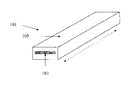
shipping from the manufacturing facility. FIG. 1 shows an exemplary elongated
thermoplastic-
based building product 101 of the present disclosure. "L" is the longitudinal
axis of the building
product 101. The longitudinal axis typically follows the linear direction of
the machining if the
product is produced by a linear machine technique such as, for example,
extruding. The
reinforcing flexing layer 102 is fully embedded (encased) by the thermoplastic
based support
layer 103. FIG. 2 shows the cross sectional profile of another exemplary
thermoplastic-based
building product 101, but with the optional outermost top layer 201 disposed
adjacent to the
thermoplastic based support layer 103.
[0042] As to thickness, the thickness will largely depend on the end use
of the
thermoplastic based building product. For example, in certain embodiments,
when the
thermoplastic based building material is a thermoplastic based wall board, the
wall board has an
average thickness of about 25 mils up to about 500 mils, including about 50
mils to about 410
mils, including about 60 mils to about 360 mils, including about 80 mils to
about 260 mils, and
including about 110 mils to about 160 mils. In certain embodiments, when the
thermoplastic
based building material is a thermoplastic based composite decking, the
composite decking has
an average thickness of about 500 mils up to about 1600 mils, including about
800 mils to about
1000 mils, and including about 200 mils to about 300 mils. As discussed above,
the average
thickness is referred to for the thermoplastic-based building product,
including the various
components that comprise the building product, because thickness may not be
consistent through
{03043787 DOCX.1 } 13
CA 02889442 2015-04-28
the profile. In certain embodiments, the thermoplastic-based building product
has a profile such
that the thickness at bottom edge is greater than the thickness at the top
edge, e.g., a wedge-
shaped profile. Accordingly, in certain embodiments, the each of the top and
bottom edge has a
thickness. In certain such embodiments, the thickness of each of the top and
bottom edges
ranges from about 25 mils to about 1,600 mils. In certain embodiments, the
thermoplastic-based
building product is designed with a tongue and groove type design so as to
aide in installation.
In certain embodiments, the building product will have a leg-type protrusion
to aid in installation
of a wall board to a wall or outer surface of a building.
[0043] The external surface of the thermoplastic-based building product may
be textured
or smooth. Thus, when the thermoplastic-based support layer is the external
surface, the
thermoplastic-based support layer may be textured or smooth. Alternatively,
when the outermost
top layer is the external surface, the outermost top layer is textured or
smooth.
Coefficient of linear thermal expansion
[0044] According to certain embodiments of the present disclosure, the
thermoplastic-
based building product has a coefficient of linear thermal expansion (CLTE)
about 7 to about 45
ppm/ C over the temperature range of -20 C to 70 C. Generally, the closer to
7 that the CLTE
is, the better the building product will perform as relatively less unwanted
expansion will occur.
In certain embodiments, the CLTE is about 20 to about 40 ppm/ C over the
temperature range of
-20 to 70 C. In certain embodiments, the CLTE is about 20 to about 30 ppm/
C, and in other
embodiments, the CLTE is about 30 to about 40 ppm/ C, over the temperature
range of -20 to
70 C.
[0045] As discussed above, thermoplastic-based building products exhibit a
CLTE that is
at least 40% lower than the CLTE of the thermoplastic-based support layer of
the building
products alone (i.e., the CLTE of just the support layer), preferably at least
a 45% lower, and
more preferably at least 50% lower.
Methods for preparing the thermoplastic-based wall board
{03043787.DOCX,1 } 14
CA 02889442 2015-04-28
100461 Another exemplary embodiment is directed to a method for preparing a
thermoplastic-based building product having a front face with a length and a
width, an opposing
back face, opposing top and bottom edges each with a thickness. The method
comprises (a)
preparing at least one thermoplastic-based support layer; (b) bonding at least
one reinforcing
flexing layer to at least one surface of the at least one thermoplastic-based
support layer, and (c)
optionally bonding at least one outermost top layer to a surface of the at
least one reinforcing
flexing layer or to a surface of the at least one thermoplastic-based support
layer.
[0047] It should be understood that the thermoplastic-based support layer
can be
prepared by various methods known to those skilled in the art of producing
elongated building
products such as vinyl siding or composite decking. In certain embodiments,
the support layer is
prepared by extruding or molding. Various types of extruding may be utilized,
including
extrusion processes traditionally used for manufacture of vinyl siding
products, composite
decking products, or other elongated types of building products.
[0048] In certain embodiments, the bonding of the at least one reinforcing
flexing layer
to the at least one surface of the at least one thermoplastic-based support
layer takes place by
extruding, calendaring, molding, or laminating. Various types of extruding can
be utilized for
the foregoing bonding, including, but not limited to, crosshead extrusion,
profile extrusion, sheet
extrusion, compression molding, blow molding, rotomolding, and long fiber
thermoplastics
molding. In certain embodiments, the at least one reinforcing flexing layer
has been extruded,
calendered, compression molded, blow molded, rotomolded, or laminated with at
least one
thermoplastic-based support layer. It should be understood that this bonding
step (b) is not
necessarily exclusive of the preparing the support layer step (a), as the two
steps may be the
same or overlap in function.
[0049] As discussed above, in certain embodiments, the at least one
reinforcing flexing
layer is provided by tape. optionally by more than one tape strip that has
been bonded or
laminated together prior to being bonded to the at least one thermoplastic-
based support layer.
The binder or adhesive associated with the tape may assist in bonding the tape
to the at least one
at least one thermoplastic-based support during the extruding, ealendaring,
molding, or
laminating. In certain embodiments, the bonding is heat bonding, which may
occur as a result of
{03043787 DOCX;1 } 15
CA 02889442 2015-04-28
separately heating the tape prior to incorporation into the at least one
thermoplastic-based
support layer, or as a result of heat applied or generated during the actual
process or step of
extruding, calendaring, molding, or laminating. In certain embodiments, the
tape has been heat
bonded to the thermoplastic-based support layer, preferably at a temperature
of about 300 F to
about 400 F.
[0050] In certain such embodiments, when the at least one thermoplastic-
based support
layer is an external surface of the building product, the method may further
include applying
texture to the at least one thermoplastic-based support layer.
100511 Furthermore, in certain embodiments, at least one outermost top
layer is bonded
to the at least one reinforcing flexing layer or to a surface of the at least
one thermoplastic-based
support layer by extruding (including co-extruding), calendaring, spraying, or
laminating. In
certain such embodiments, the method further includes applying texture to the
at least one
outermost surface.
[0052] Another exemplary embodiment is directed to a method for preparing a
thermoplastic-based wall board having a front face with a length and a width,
an opposing back
face, opposing top and bottom edges each with a thickness. The method
comprises (a) preparing
at least one thermoplastic-based support layer having an average thickness of
about 10 mils to
about 490 mils, including about 40 mils to about 400 mils, including about 50
mils to about 350
mils, including about 70 mils to about 250 mils, including about 100 mils to
about 150 mils; (b)
bonding at least one reinforcing flexing layer having a thickness of about 10
to about 30 mils,
preferably about 10 to about 20 mils, to at least one surface of the at least
one thermoplastic-
based support layer, and (c) optionally bonding at least one outermost top
layer having a
thickness of about 1 to about 10 mils to a surface of the at least one
reinforcing flexing layer or
to a surface of the at least one thermoplastic-based support layer.
EXAMPLES
[0053] The following examples illustrate certain exemplary embodiments
according to
the present disclosure. The examples are given solely for the purpose of
illustration and are not
{03043787 DOCX.1 } 16
CA 02889442 2015-04-28
to be construed as limitations of the general inventive concepts, as many
variations thereof are
possible without departing from the spirit and scope of the general inventive
concepts.
CLTE Analytical Method
[0054] Unless otherwise described herein, the respective CLTE measurements
of the
specimens disclosed in these Examples were obtained in the following manner. A
sample,
predominantly rectangular in shape, was taken from the specimen to be tested
and subjected to a
thennomechanical analysis (TMA) using a TMA Q400 Thermomechanical Analyzer at
a
temperature setting range of -20 C to 70 C using a ramping method of 4
C/min and a N2 purge
rate of 50 mL/min. All samples were polished with sand paper before
introduction into the
TMA. These measurements were obtained in accordance with ASTM E831.
COMPARATIVE EXAMPLE 1 - Preparation of PVC Control Sample and Comparative
Fiber Reinforced PVC Samples
[0055] For this Comparative Example, neat, rigid polyvinyl chloride polymer
was
utilized as the control (referred to herein as "PVC Control"). Three different
experimental
compositions were prepared using the same polyvinyl chloride in combination
with: 30 wt % 0.5
inch glass fiber (Comparative Example 1A and 1B), 50 wt 0.5 inch glass fiber
(Comparative
Examples 1C and 1D), and 20 wt % short fiber carbon fiber (Comparative Example
1E).
[0056] Unless otherwise indicated, the polyvinyl chloride used in the
Examples of the
present disclosure was enhanced PVC (also denoted herein as ePVC, available
from Americhem,
Inc. of Cuyahoga Falls, Ohio). The glass fibers used were fiberglass and
commercially available.
Specifically, the 0.5 inch glass fibers were DS5102--13C, 13 micrometer
filament diameter
(Owens Corning, Toledo, Ohio), Advantex glass type-boron free fibers. The
fiberglass was
sized by the manufacturer to increase compatibility with the polyvinyl
chloride. The carbon
fibers used were short carbon fiber, i.e., about 200-300 mils length, and
generally having a
diameter of 7 pm and commercially available as PAN (polyacrylonitrile)-
precursor, milled
carbon fiber from Finite Fiber of Akron, Ohio. The carbon fibers were sized by
the manufacturer
to increase compatibility with the polyvinyl chloride.
(03043787 DOCX;1 } 17
CA 02889442 2015-04-28
[0057] A single screw extruder was utilized for the long fiber extrusion
(Model No.
150S2310 from C.A. Lawton Company, Wisconsin). The barrel of the extruder was
approximately 3 inches in diameter and had a length to diameter ratio of about
80:1. It was not
equipped with any barrel cooling. The extruder had 10 electric zones, with the
last zone
allowing for material accumulation and pushing out of a charge based on a
programmed finite
length of screw turns. It was also configured so that a hot, compounded charge
could be placed
into an attached mold for compression molding. For these Examples an 11 inch x
18 inch mold
was utilized. The resulting samples produced from this mold were about 11 inch
x about 18
inches x about 250 mils.
[0058] The melt temperature of the extrudate was measured to be 415 F.
The mold
conditions were 165 F and 3,000 psi, 30 seconds of cycle time. 10 neat PVC
panels were
molded. These panels were the PVC Control. The CLTE was obtained for the PVC
Control and
is shown in Table 1 below.
[0059] Then, about 30 lbs PVC comprising 30 wt % of the 0.5 inch glass
fibers (typically
referred to as "long fiber") was added to the extruder and the output was
slowed to provide more
residence time in the barrel. At the natural polyvinyl chloride to glass-fiber
product transition,
the first panel that was molded contained random, high fiber concentration
regions. Thereafter,
with the additional residence time, more uniform looking panels were produced
(filled out and
homogeneous appearance). The melt temperature of the extrudate was measured to
be 450 F.
panels were produced. The CLTE was measured and shown in Table 1 below as
Comparative
Examples IA and 1B. Comparative Example IA refers to the CLTE measured through
the cross
section, middle of the panel sample being measured (e.g., measured near the
centerline of the
cross section), and Comparative Example 1B refers to the measurement of the
cross section, near
the outer edge of the same sample.
[0060] Thereafter, a bucket of neat polyvinyl chloride was placed in the
hopper to mark
the transition to the next trial. Then, about 30 lbs PVC comprising 50 wt % of
the 0.5 inch glass
fibers (long fiber) was added to the extruder, and allowed to sit for a few
minutes to ensure
mixing. The molded panels improved in fiber distribution and homogeneity with
each
progressive sample, and even though the parts were never filled out entirely,
they were
{03043787 DOCX,1 } 18
CA 02889442 2015-04-28
reasonable in overall appearance. The melt temperature of the extrudate was
measured to be 450
F. 10 panels were produced. The CLTE was measured and shown in Table 1 below
as
Comparative Examples 1C and 1D. Comparative Example 1C refers to the CLTE
measured
through the cross section, middle of the panel sample being measured (e.g.,
measured near the
centerline of the cross section), and Comparative Example 1D refers to the
measurement of the
cross section, near the outer edge of the same sample.
100611 In another trial, about 5 lbs of a general purpose rigid PVC (this
is the same PVC
as Example 4 below, but not for Comparative Examples 1A-1D) comprising 20 wt %
of the short
carbon fiber was added to a 25 mm conical counter rotating lab extruder with
slit die. The melt
temperature of the extrudate was measured to be 380 F. A panel 20 feet long
was produced.
The CLTE was measured and shown in Table 1 below as Comparative Example 1E.
EXAMPLE 2 -Extruded PVC Containing Fiberglass Tape as the Reinforcing Flexing
Layer
[0062] In this Example, PVC-based support layer panels containing a
fiberglass
impregnated tape as the reinforcing flexing layer were produced. As discussed
in more detail
below, the fiberglass impregnated tape contains continuous fiberglass fibers
that are
unidirectionally oriented in the tape. The tape was bonded to the PVC-based
support layer using
crosshead extrusion via the use of an aluminum stabilizer strip.
[0063] The materials utilized for this Example included 300 lbs. of a
beige rigid,
enhanced PVC (ePVC, the same ePVC used in Comparative Examples 1A-1D), a
commercially
available glass fiber tape containing about 60-70 wt % glass fiber and a PETG
binder, where the
fibers are unidirectionally oriented in the tape. This tape has a 400 gsm
(grams per square meter)
density and a thickness of about 12 mils. The tape was slit to about 0.5 inch
to accommodate the
crosshead tooling for this Example.
[0064] The extruding equipment utilized in this Example included a 1.5
inch Davis
Standard single crosshead extruder with a 60 mesh screen pack at 90 to the
stabilizer feed.
When the trial began, the line (extruder) was hot at 350 F and ready to go.
Downstream
equipment included a chilled water tank with cleated belt puller (RDN
Manufacturing Co., Inc.,
(03043787 DOCX;1 } 19
CA 02889442 2015-04-28
Bloomingdale, Illinois). Strips of crosshead finished product were cut into 3-
4 foot long
specimens.
[0065] The line was strung up with the standard aluminum stabilizer strip
("stabilizer") at
about 7 feet/min. Extruder conditions were monitored and found to be stable,
with no drift in
zone temperatures and the adaptor pressure transducer was about 6,000 psi. The
rupture disk
was rated for 9,000 psi. The PVC appeared to flow well, and also appeared to
bond very well to
the aluminum stabilizer. A small about 8X optical comparator on the line was
utilized to look at
the cross sections. The PVC containing the aluminum stablizer strip was taken
as a control
(hereinafter referred to as "Crosshead PVC Control"). The aluminum stablizer
strip is
completely embedded/enclosed within the PVC matrix.
[0066] Then, after about 10 minutes the tape was spliced in. The tape for
this example is
completely embedded/enclosed within the PVC matrix. Some outgassing was
observed at the
die exit which was believed to be from the polyvinyl chloride. Twenty 3 foot
strips were taken
and placed in a box for later evaluation as Example 2A. Based upon examination
of the cross
sections, some "waviness" could be seen as the tape wasn't entirely flat like
the aluminum strip
had been. Some bubbles could also be seen in the tape itself; by monitoring
the tape melt on a
hot plate near the line it was verified that the tape was softening and
releasing/curling stresses
within itself
[0067] Thereafter, speed was increased to 15 feet/minute, but no apparent
change in tape
waviness/distribution across the width of the composite strip resulted. Strips
were again taken at
this condition as Example 2B. Overall, use of the aluminum strip alone
resulted in a flat product,
with good adhesion. Use of the tape either results in a somewhat wavy,
irregular cross-section,
with some internal tape voids, but good adhesion or (after increasing the
speed) a generally flat-
laying, but still somewhat irregular cross-section, with slight evidence of
internal tape voiding.
[0068] Thereafter, the temperature was dropped to 340 F, and a spike was
observed in
extruder adaptor pressure to about 8,000 psi. Conditions were held and dried
PVC material was
dropped (extruded 2 hours at 150 F), but no changes were observed. Overall,
no line breaks
occurred and no issues were identified other than the quality of the tape.
Over time some
"fuzzing" was observed at the crosshead die inlet, and the tape was
inconsistent in width, as the
{03043787 DOCX,1 20
CA 02889442 2015-04-28
tape is somewhat brittle and not very amenable to slitting. All composite
finished strips
maintained excellent integrity and flexibility. Cohesive tape failure (where
the fibers/binder of
the tape separated from each other) was observed in the finished parts upon
physically pulling
apart the sandwich with pliers. The cohesive tape failure showed bonding of
the tape to matrix.
[0069] CLTE (measured according to ASTM E831) were obtained on the
Crosshead
PVC Control as well as on Examples 2A and 2B containing the fiber glass tape.
Results are
provided in Table 1.
[0070] As a comparison, the CLTE was obtained for the tape alone, i.e., a
single ply of
the PETG-glass fiber tape containing about 60-70 wt % glass fiber where the
fibers are
unidirectionally oriented in the tape. These results are shown in Table 1 as
"Unidirectional
Fiberglass Tape Control."
EXAMPLE 3 - Dual-ply PETG Fiberglass Tape and Dual-ply PET-containing
Fiberglass
Tape
100711 Another trial was conducted, using modified versions of the
fiberglass tape used
in Example 2. More specifically, in the first modification, 2 single-ply PETG-
fiberglass
impregnated tapes (of the type utilized in Example 2) were laminated together
to create a larger
glass volume cross-ply tape, where the fibers of each ply are oriented at a 0
and 90 with respect
to each other. In the second modification, another dual-ply fiberglass tape
was prepared in the
same manner as the 2 single-ply PETG-fiberglass impregnated tapes of this
Example, but it
contained a PET binder (which has a lower melting temperature) instead of the
PETG binder.
[0072] The thermoplastic materials utilized for the trial included 50 lbs.
of the same
enhanced PVC used in Example 2. The line of the crosshead extruder used in
Example 2 was
again strung up with the standard aluminum strip ("stabilizer") at about 7
ft/min. The conditions
were the same as that of Example 2 with the extruder being flood fed and
barrel/die temps set to
360 F, 27 RPM, generating about 5000 psi adaptor pressure. The "lower"
melting dual-ply
PET-containing tape was spliced in to the aluminum strip by hand, thereby
avoiding a line
shutdown. The dual-ply tape was found to be more stable in feed generally as
compared to the
(03043787 DOCX,1 } 21
CA 02889442 2015-04-28
single-ply tape due to the increased thickness and the curling phenomenon at
die entry that was
observed in the previous was not seen this time.
[0073] The resulting strip through the water bath and out of the puller was
cut and
mechanically separated with pliers to evaluate the polyvinyl chloride bond to
the tape. Using the
pliers, a cohesive tape failure was not achieved, but an adhesive failure was
observed on just the
bottom side where the tape pulled completely away from the PVC. A switch was
made to the
higher melting PETG-fiberglass impregnated dual-ply tape, and the same result
was observed.
In subsequent tests, a manual heat gun was applied to the PETG dual-ply tape
prior to die entry,
and a cohesive bond failure was then observed. IR lamps were then brought to
the line to
substitute for the heat gun. Once again, an adhesive failure was observed in
the strip on the
bottom of the dual-ply PETG-fiberglass impregnated tape. The heat also
decreased the
stability/tension of the tape as the tape could not be kept across the entire
width of the strip and it
curled upon itself in the die.
[0074] After a period of operating at 360 F, the extruder temps were
dropped and
remove the IR heating to "reset" conditions. The tape also appeared to be
outgassing in the heat
gun/IR lamp portion of this Example. Further, the standard aluminum stabilizer
was spliced in to
help clean the tool from buildup and this kept the line up and running. The
lower melt PET dual-
ply tape material was spliced back in and no cohesive failures were observed.
[0075] Finally, the high melt PETG-fiberglass impregnated dual-ply was
spliced back in
at about 360 F barrel zones, 350 F die temperature, with IR lamp applied,
and cohesive failure
was achieved for the second time. Ten 3 ft strips had been cut for each set
point roughly. A
buildup of glass fiber on the felt pads/vise which likely applied initial
tension to the tape.
[0076] Overall, both dual-ply tapes were more consistent in width which was
an
improvement over Example 2. The lower melting PET-containing fiberglass
impregnated tape
had an increased amount of glass fraying/fuzz as compared to the PETG-
containing fiberglass
impregnated tape. Both dual tapes were more stable and did not "curl" upon
entry to the
crosshead die, an improvement over Example 2. Using mechanical pliers no
cohesive bond
failure was generated with the lower melting PET fiberglass impregnated tape;
however, a
cohesive bond failure was generated with the higher melting PETG fiberglass
impregnated tape.
03043787.DOCX; I I 22
CA 02889442 2015-04-28
EXAMPLE 4- Compression Molded PVC
[0077] In another trial, stainless steel molds were designed and
constructed. These molds
were utilized to compress one or more PVC-containing support layer(s) with a
reinforcing
flexing layer. The mold were designed so as to minimize lateral movement of
the tape (and
fibers) during compression. Previous trials had resulted in fibers spreading
from side-to-side and
the molds were designed to assist the tape in holding its shape. As those
skilled in the art will
understand molds of differing dimensions, particularly larger molds, applying
the same concepts
could be designed for commercial production purposes. Unless otherwise
indicated, the PVC
used in this Example was the same general purpose rigid PVC material utilized
in Comparative
Example 1E.
[0078] Using the molds, a single-ply unidirectional PETG- fiberglass
impregnated tape
(the type utilized in Example 2) was sandwiched between two layers of PVC
matrix. This glass
tape PVC sandwich is referred to herein as Example 4A. The thermoplastic
materials utilized for
the trial included the rigid PVC material. The PVC sandwich was prepared
according to the
following procedure, about 5 lbs. of the PVC was extruded into about 1/8 inch
strips with a 25
mm conical counter rotating extruder. 1 inch x 3 inch pieces in the machine
direction were cut
out of the strips, pressed down further to smaller thicknesses of about 30-70
mils, and a sandwich
was assembled with a tape in the middle for a target finished thickness of
about 125 mils. Metal
shims were utilized to make smaller finished thicknesses. 2 pieces of Teflon
were used on the
top and bottom of the sandwich to prevent sticking to the mold. The mold was
soaked on a
Carver press at 400 F for 1-2 hrs. The sandwich was then placed into the mold
and the mold
was placed into the press at various pressures of about 500 psi to about 30
tons per square inch
for 30 s to 2 min. Upon removal the part, temperature was about 300 F and
placed in between
flat stainless steel plates for cooling for about 1-2 min. in a water cooled
press. Upon demolding,
the glass tape molded PVC "sandwich" was at room temperature and stable with
no camber. The
CLTE was obtained for this sandwich of Example 4A. Results are provided in
Table 1 for
Example 4A.
[0079] Using the molds, 2 single-ply PETG- fiberglass impregnated tapes
(the type
utilized in Example 2) were sandwiched between three alternating layers of PVC
matrix. This 2-
{03043787 DOCX,1 } 23
CA 02889442 2015-04-28
glass tapes PVC sandwich (layered between 3 layers of PVC) is referred to
herein as Example
4B. The thermoplastic materials utilized for the trial included 1 lb. of the
rigid PVC compound.
The PVC sandwich was prepared same as above however, the sandwich was
assembled with
alternating layers of PVC (3 total layers) and tape (two total layers) such
that the tapes were
symmetrically distributed throughout the cross-section to form the two glass
tape molded PVC
"sandwich." Specimens were also prepared with 3 layers of single-ply tapes
laminated to each
other in between 2 layers of PVC, at 00 orientation to each other (thus
creating a multilayer
unidirectional fiber tape). The tapes adhered to themselves with heat and
pressure of the mold.
The 3 glass layer PVC "sandwich" (between the 2 layers of PVC) is referred to
herein as
Example 4C. The CLTE was obtained for these sandwiches of Examples 4B and 4C.
Results
are provided in Table 1 for Examples 4B and 4C.
EXAMPLE 5- Compression Molded Polypropylene
100801 Using the molds described in Example 4, a single-ply 85 wt % aramid
fiber
impregnated tape containing a polypropylene binder was sandwiched between two
layers of a
polypropylene resin matrix. The aramid fiber impregnated tape has a 178 gsm
density. The
polypropylene utilized for the trial included 1 lb. of a 35 MI homopolymer
polypropylene (from
Braskem of Philadelphia, Pennsylvania). The resin was fluxed in a Wright split
bowl mixer and
pressed out with a Carver press to about 70 mils thickness sheets. The sheets
were assembled
with the tape as above but at a press temperature of 450 F and primarily 500
psi pressure to
create a polypropylene(PP)/aramid fiber impregnated tape molded "sandwich."
The CLTE was
obtained for this sandwich. Results are provided in Table 1.
[0081] As a comparison, the CLTE of the polypropylene alone, i.e., without
the aramid
fiber impregnated tape, subjected to the same conditions discussed above in
Example 5 was
obtained. The results are shown in Table 1 as "Polypropylene Control."
EXAMPLE 6- Compression Molded HDPE
[0082] Using the molds described in Examples 4 and 5, a commercially
available single-
ply 60-70 wt % fiberglass impregnated tape containing an olefin-type binder
was sandwiched
between two layers of a high density polyethylene (HDPE) based-resin matrix.
The polyethylene
{03043787.DOCX;1 } 24
CA 02889442 2015-04-28
utilized for the trial included 5 lbs. of a commercially available HDPE
composite containing
about 50% by weight rice hulls and paper byproduct filler. The HDPE-composite
resin was
milled on a hot 2 roll mill and pressed out to thicknesses of about 60-125
mils. Sandwiches were
prepared in the manner described above (e.g., in Examples 4A and 5) at a press
temperature of
440 F to create a HDPE-composite/tape molded "sandwich." The CLTE was
obtained for this
sandwich. Results are provided in Table 1 as Example 6 (the CLTE measurements
were
duplicated, and both results are shown in Table 1).
[0083] As a comparison, the CLTE of the commercially available HDPE
composite
alone, i.e., without the fiberglass impregnated tape of this Example,
subjected to the same
conditions under the mold discussed above (in Example 6) was obtained. The
results are shown
in Table 1 as "HDPE Composite Control."
[0084] As a further comparison, the CLTE of neat HDPE, subjected to the
same
conditions under the mold discussed above (in Example 6) was also obtained.
The results are
shown in Table 1 as "HDPE Control."
COMPARATIVE EXAMPLE 7- Other Materials
[0085] As a comparison, the CLTE of other commercially available products
was
obtained. These results are shown in Table 1 as Comparative Examples 7A-7F.
COMPARATIVE EXAMPLE 8- Tape Laminated to PVC Siding
[0086] A single-ply strip of the fiberglass impregnated unidirectional
tape employed in
Example 2 (with PETG binder) was laminated to a commercially available piece
of PVC siding
at 80 feet/minute. This was accomplished under the following conditions:
several discreet tape
lengths of 1-2 feet were fed by hand into an embosser nip, where the tape
stuck and traversed
through the siding line. The siding was not able to be calibrated to shape due
to the tape
interrupting the melt. The CLTE for this sample was obtained and listed in
Table 1 as
Comparative Example 8. Although the CLTE at 27 ppm/ C is consistent with the
samples
prepared in which the tape is completely embedded within the PVC matrix, it
should be
understood that this tape-laminated PVC siding distorted (i.e., exhibited
camber) during the
(03043787 DOCX:1 1 25
CA 02889442 2015-04-28
lamination of the tape to the PVC siding. Such camber did not occur in the
specimens obtained
from Examples 2-6.
Table 1
Example Description CLTE Result
(ppm/ C), -20 C to 70
oc
Comparative ACCOYA Wood (commercial
acetylated 4
Example 7A wood product)
Comparative ULTREX (commercial polyester
thermoset 5
Example 7B Apex pultrusion product)
Comparative GAMRA PUR (commercial
polyurethane 5
Example 7C thermoset pultrusion)
Comparative HARDIE board (commercial
board fiber 6
Example 7D cement product)
Unidirectional Unidirectional fiberglass tape (PETG 10
Fiberglass Tape binder, about 60-70% by weight glass)
Control
Example 4C 3 glass layer PVC sandwich
14
Comparative 50% glass fiber reinforced
(long fiber) PVC 19
Example 1C
Comparative BORAL trim board (commercial
thermoset 20
Example 7E foamed polyurethane reinforced with fly
ash)
Comparative 20% carbon fiber reinforced
(short fiber) 22
Example lE PVC
Comparative 50% glass fiber reinforced
(long fiber) PVC 22
Example 1D
Example 4B 2 glass tapes molded PVC
sandwich 23
Example 2A Crosshead PVC-glass strip,
7'/minute 25
Example 5 PP/aramid fiber impregnated tape sandwich 25
Example 4A Molded PVC/tape sandwich
26
Example 2B Crosshead PVC-glass strip,
15'/minute 27
Comparative PVC Siding with glass tape
laminated to 27
Example 8 back side
Comparative 30% glass fiber reinforced
(long fiber) PVC 33
Example lA
Comparative 30% glass fiber reinforced
(long fiber) PVC 37
Example 1B
Crosshead PVC Crosshead PVC-metal strip, 7'/minute 38
Control
{03043787 DOCX,1 } 26
CA 02889442 2015-04-28
Example 6 HDPE composite/tape molded sandwich 37, 40
Comparative Foamed, filled PVC cladding (EVERLAST 41
Example 7F Polymeric Cladding, a commercial product
of foamed rigid PVC profile piece,
reinforced with talc available)
PVC control PVC (neat PVC) 65
HDPE HDPE composite material 75
Composite
Control
Polypropylene Polypropylene (neat polypropylene) 103
Control
HDPE Control HDPE (neat HDPE) 129
As discussed above, the CLTE results in Table 1 were measured in accordance
with ASTM
E831 .
[0087] To the extent that the term "includes" or "including" is used in
the specification or
the claims, it is intended to be inclusive in a manner similar to the term
"comprising" as that term
is interpreted when employed as a transitional word in a claim. Furthermore,
to the extent that
the term "or" is employed (e.g., A or B) it is intended to mean "A or B or
both." When the
applicants intend to indicate "only A or B but not both" then the term "only A
or B but not both"
will be employed. Thus, use of the term "or" herein is the inclusive, and not
the exclusive use.
Also, to the extent that the term "in" or "into" is used in the specification
or the claims, it is
intended to additionally mean "on" or "onto," respectively. Furthermore, to
the extent the term
"connect" is used in the specification or claims, it is intended to mean not
only "directly
connected to" but also "indirectly connected to" such as connected through
another component
or components.
[0088] While the present application has been illustrated by the
description of
embodiments thereof, and while the embodiments have been described in
considerable detail, it
is not the intention of the applicants to restrict or in any way limit the
scope of the appended
claims to such detail. Additional advantages and modifications will readily
appear to those
skilled in the art. Therefore, the application, in its broader aspects, is not
limited to the specific
details, the representative compositions and processes, and illustrative
examples shown and
described. Accordingly, departures may be made from such details without
departing from the
spirit or scope of the general inventive concept.
{03043787 DOCX,1 27