Language selection

Search

Patent 2889924 Summary

Third-party information liability

Some of the information on this Web page has been provided by external sources. The Government of Canada is not responsible for the accuracy, reliability or currency of the information supplied by external sources. Users wishing to rely upon this information should consult directly with the source of the information. Content provided by external sources is not subject to official languages, privacy and accessibility requirements.

Claims and Abstract availability

Any discrepancies in the text and image of the Claims and Abstract are due to differing posting times. Text of the Claims and Abstract are posted:

  • At the time the application is open to public inspection;
  • At the time of issue of the patent (grant).
(12) Patent Application: (11) CA 2889924
(54) English Title: ROTOR BLADE FOR A WIND TURBINE
(54) French Title: PALE DE ROTOR POUR EOLIENNE
Status: Deemed Abandoned and Beyond the Period of Reinstatement - Pending Response to Notice of Disregarded Communication
Bibliographic Data
(51) International Patent Classification (IPC):
  • F03D 01/06 (2006.01)
(72) Inventors :
  • WEPFER, HANS (Switzerland)
(73) Owners :
  • WEPFER TECHNICS AG
(71) Applicants :
  • WEPFER TECHNICS AG (Switzerland)
(74) Agent: NORTON ROSE FULBRIGHT CANADA LLP/S.E.N.C.R.L., S.R.L.
(74) Associate agent:
(45) Issued:
(86) PCT Filing Date: 2013-10-29
(87) Open to Public Inspection: 2014-05-08
Availability of licence: N/A
Dedicated to the Public: N/A
(25) Language of filing: English

Patent Cooperation Treaty (PCT): Yes
(86) PCT Filing Number: PCT/CH2013/000188
(87) International Publication Number: CH2013000188
(85) National Entry: 2015-04-29

(30) Application Priority Data:
Application No. Country/Territory Date
2171/12 (Switzerland) 2012-10-29

Abstracts

English Abstract

The present invention relates to a rotor blade (1) and a corresponding rotor for a wind turbine having a reduced rotor diameter and improved performance. The rotor blade (1) for a wind turbine has a blade root (3) with a defined first diameter as an attachment to a hub, and a rotor blade end (2), with a second defined diameter, opposite the blade root. The rotor blade (1) also has a trailing edge (7) and a leading edge (8) in relation to the direction of rotation of the rotor blade (1) during operation. The leading edge (8) and the trailing edge (7) each have a curvature. The first diameter is smaller than the second diameter.


French Abstract

L'invention concerne une pale de rotor (1) et un rotor correspondant d'une éolienne présentant un diamètre de rotor réduit pour une performance accrue. Cette pale de rotor (1) destinée à une éolienne comporte une emplanture (3) présentant un premier diamètre défini, comme élément de liaison à un moyeu, et une extrémité (2) de pale de rotor opposée à l'emplanture et présentant un second diamètre défini. Elle présente en outre un bord de fuite (7) et un bord d'attaque (8) par rapport à la direction de rotation de la pale de rotor (1) lorsque celle-ci est en fonctionnement. Le bord d'attaque (8) et le bord de fuite (7) présentent chacun une courbure. Le premier diamètre est inférieur au second diamètre.

Claims

Note: Claims are shown in the official language in which they were submitted.

Claims
1 . A rotor blade (1) for a wind turbine, comprising
a) a wing root (3) as an attachment to a hub, with a first diameter, and
b) a rotor blade end (2) which is opposite the wing root (3), with a second
diameter, and
c) a trailing edge (7) and a leading edge (8) with respect to the slicing
direction of the rotor
blade (1) during operation, and wherein the leading edge (8) and the trailing
edge (7) each
have a curvature, and characterized in that the first diameter is smaller than
the second
diameter.
2. The rotor blade (1) as claimed in claim 1, wherein the diameter of the
rotor blade (1) increases
from the first diameter at the wing root as far as the second diameter at the
rotor blade end (2).
3. The rotor blade (1) as claimed in either of claims 1 and 2, wherein the
rotor blade (1) has a rotor
camber axis (12) which runs in such a manner that the leading edge (8), in
front view, has a first
camber height (4) at the wing root (3) that is lower than a central camber
height (5) in the center
of the rotor blade (1) that, in turn, is higher than an end-side camber height
(6) at the rotor blade
end (2).
4. The rotor blade (1) as claimed in either of claims 1 and 2, wherein the
rotor blade (1) has a rotor
camber axis (12) which runs in such a manner that the leading edge (8), in
front view, has a first
camber height (4) at the wing root (3) that is in particular substantially the
same height as a
central camber height (5) in the center of the rotor blade (1) that, in turn,
is higher than an end-
side camber height (6) at the rotor blade end (2).
5. The rotor blade (1) as claimed in either of claims 1 and 2,
characterized in that the rotor blade (1)
has a rotor camber axis (12) which runs in such a manner that the leading edge
(8), in front view,
has a first camber height (4) at the wing root (3) that is higher than a
central camber height (5) in
-6-

the center of the rotor blade (1) that, in turn, is higher than an end-side
camber height (6) at the
rotor blade end (2).
6. The rotor blade (1) as claimed in one of claims 1 to 5, wherein the
rotor blade end (2) comprises
a double winglet (9).
7. The rotor blade (1) as claimed in one of claims 1 to 5, wherein the
rotor blade end (2) comprises
a winglet (10) on the upper side of the profile.
8. The rotor blade (1) as claimed in one of claims 1 to 6, wherein the rotor
blade (2) comprises a
winglet (11) on the inner side of the profile.
9. The rotor blade (1) as claimed in one of claims 1 to 8, wherein the rotor
blade (1) is
manufactured from an aluminum plate, in particular is composed of aluminum.
10. The rotor blade (1) as claimed in one of claims 1 to 8, wherein the rotor
blade (1) is
manufactured from composite material, in particular is composed of composite
material.
11. A rotor comprising at least one rotor blade (1) as claimed in one of
claims 1 to 10, wherein the
rotor comprises two to sixteen rotor blades (1) as claimed in claim 1.
-7-

Description

Note: Descriptions are shown in the official language in which they were submitted.


CA 02889924 2015-04-29
=
Rotor blade for a wind turbine
Technical field
The present invention relates to a rotor blade and to a corresponding rotor
for wind turbines.
- 1 -

CA 02889924 2015-04-29
Prior art
Long, very slender rotor blades for 3-wing wind turbines have long been known.
In order to obtain
greater performances, the rotor blades to date have become longer and the
rotor circle greater. This
increases the moment of inertia which, in turn, results in it scarcely being
possible any more to make
use of gusts of wind. It is also not possible to suppress blade tip noises.
The production and
maintenance costs remain very high.
It is therefore an object of the invention to provide a rotor blade and a
corresponding rotor having
considerably shorter rotor blades and a narrower rotor circle associated
therewith. In particular, the
intention is to provide a rotor blade and a rotor, the structural
configuration of which saves on
material and maintenance costs.
Summary of the invention
The achievement of the object is defined by the features of the independent
claims.
One aspect of the present invention relates to a rotor blade for a wind
turbine. The rotor blade has a
wing root as an attachment to a hub, with a defined first diameter, and a
rotor blade end which is
opposite the wing root, with a defined second diameter. In addition, the rotor
blade has a trailing
edge and a leading edge with respect to the slicing direction, i.e. the
direction in which the rotor
blade rotates during operation, wherein the leading edge and the trailing edge
each have a curvature.
Said first diameter of the rotor blade is smaller than the second diameter.
In a particular embodiment, the diameter of the rotor blade increases from the
first diameter at the
wing root as far as the second diameter at the rotor blade end. Within the
context of the present
invention, this means that the diameter increases from the wing root outward
to the rotor blade end.
In a particular embodiment, the rotor blade has a rotor camber axis which runs
in such a manner that
the leading edge, in front view, has a first camber height at the wing root
that is lower than a central
- 2 -

CA 02889924 2015-04-29
camber height in the center of the rotor blade that, in turn, is higher than
an end-side camber height
at the rotor blade end.
In an alternative particular embodiment, the rotor blade has an alternative
rotor camber axis which
runs in such a manner that the leading edge, in front view, has a first camber
height at the wing root
that is in particular substantially the same height as a central camber height
in the center of the rotor
blade that, in turn, is higher than an end-side camber height at the rotor
blade end.
In a further alternative particular embodiment, the rotor blade has a rotor
camber axis which runs in
such a manner that the leading edge, in front view, has a first camber height
at the wing root that is
higher than a central camber height in the center of the rotor blade that, in
turn, is higher than an end-
side camber height at the rotor blade end.
In a particular embodiment, the rotor blade end comprises a double winglet.
In a particular embodiment, the rotor blade end comprises a winglet on the
upper side of the profile.
In a particular embodiment, the rotor blade end comprises a winglet on the
inner side of the profile.
In a particular embodiment, the rotor blade is manufactured from an aluminum
plate, in particular
said rotor blade is composed of aluminum.
In a particular embodiment, the rotor blade is manufactured from composite
material, in particular
said rotor blade is composed of composite material.
A further aspect of the present invention relates to a rotor comprising at
least one rotor blade
described at the beginning. The rotor is equipped with two to sixteen such
rotor blades which are
connected via the wing roots thereof to a hub.
-3 -

CA 02889924 2015-04-29
Brief description of the drawings
Further advantageous embodiments and combinations of features of the invention
will become
apparent from the detailed description given below and from all of the patent
claims.
The performance compensation of said comparatively smaller rotor is explained
in more detail below
with reference to the drawing. In the drawings used to illustrate the
exemplary embodiment:
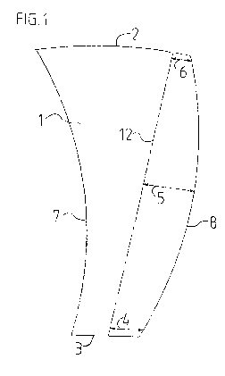
Fig.1 shows a top view of a rotor blade according to the invention;
Fig.2 shows a front view of a rotor blade according to the invention;
Fig.3 shows a rotor blade end in side view with a double winglet;
Fig.4 shows a rotor blade end in front view with a double winglet;
Fig.5 shows a rotor blade end in side view with a winglet on the upper side of
the profile;
Fig.6 shows a rotor blade end in front view with a winglet on the upper side
of the profile;
Fig.7 shows a rotor blade end in side view with a winglet on the inner side of
the profile, and
Fig.8 shows a rotor blade end in front view with a winglet on the inner side
of the profile.
In principle, identical parts are provided with identical reference signs in
the figures.
Ways of implementing the invention
Fig. 1 shows a rotor blade I where, according to the invention, the trailing
edge 7 and the leading
edge 8 are provided with a radius, that is to say, leading edge 8 and trailing
edge 7 each have a
curvature. The curvature extends in a sickle-shaped manner from a wing root 3,
and therefore the
rotor blade 1 is produced in the shape of a scythe. The diameter of the rotor
blade 1 at the wing root
3 is shorter than the diameter of the rotor blade 1 at the rotor blade end,
that is to say, the depth of the
rotor blade increases outward. In other words, the rotor blade 1 shown
involves a sickle shape which
is wider toward the outside, that is to say at the end facing away from a hub
(not shown) than at the
hub-side end. The rotor blade end 2 likewise has a curvature. The respective
curvatures of the
- 4 -

CA 02889924 2015-04-29
leading edge 8 and of the trailing edge 7 do not run parallel to each other,
but rather are increasingly
remote from each other over the course of the distance from the wing root 3.
In addition, the rotor blade shown has a camber. A rotor blade camber axis 12
with the corner values
thereof, and with the first camber height 4, the central camber height 5 and
the end-side camber
height 6 defines the shape here of the rotor blade 1.
The camber of the rotor blade according to the invention can be seen better in
Fig. 2. The latter
shows a front view of a rotor blade 1, that is to say, as viewed from the
direction into which the rotor
blade moves during operation, where it is apparent that the leading edge 8
becomes shallower
outward toward the rotor blade end 2, i.e. becomes less high. The end-side
camber height 6 is lower
in comparison to the central camber height 5. The central camber height 6 is
higher in comparison to
the first camber height 4 at the wing root 3.
Figs. 3 and 4 show a double winglet 9 at the rotor blade end 2 where an
outflow of air on the inside
and also on the upper side is prevented over the entire rotor blade end 2.
Figs. 5 and 6 show a winglet 10 on the rotor blade end where the outflow of
air is prevented over the
entire upper side of the profile.
Figs. 7 and 8 show a winglet 11 on the rotor blade end 2 where the outflow of
air is prevented over
the entire inner side of the profile.
-5 -

Representative Drawing
A single figure which represents the drawing illustrating the invention.
Administrative Status

2024-08-01:As part of the Next Generation Patents (NGP) transition, the Canadian Patents Database (CPD) now contains a more detailed Event History, which replicates the Event Log of our new back-office solution.

Please note that "Inactive:" events refers to events no longer in use in our new back-office solution.

For a clearer understanding of the status of the application/patent presented on this page, the site Disclaimer , as well as the definitions for Patent , Event History , Maintenance Fee  and Payment History  should be consulted.

Event History

Description Date
Common Representative Appointed 2019-10-30
Application Not Reinstated by Deadline 2019-10-29
Time Limit for Reversal Expired 2019-10-29
Deemed Abandoned - Failure to Respond to Maintenance Fee Notice 2018-10-29
Inactive: Abandon-RFE+Late fee unpaid-Correspondence sent 2018-10-29
Inactive: Cover page published 2015-05-26
Inactive: Notice - National entry - No RFE 2015-05-07
Inactive: IPC assigned 2015-05-07
Inactive: First IPC assigned 2015-05-07
Application Received - PCT 2015-05-07
National Entry Requirements Determined Compliant 2015-04-29
Application Published (Open to Public Inspection) 2014-05-08

Abandonment History

Abandonment Date Reason Reinstatement Date
2018-10-29

Maintenance Fee

The last payment was received on 2017-10-30

Note : If the full payment has not been received on or before the date indicated, a further fee may be required which may be one of the following

  • the reinstatement fee;
  • the late payment fee; or
  • additional fee to reverse deemed expiry.

Patent fees are adjusted on the 1st of January every year. The amounts above are the current amounts if received by December 31 of the current year.
Please refer to the CIPO Patent Fees web page to see all current fee amounts.

Fee History

Fee Type Anniversary Year Due Date Paid Date
Basic national fee - standard 2015-04-29
MF (application, 2nd anniv.) - standard 02 2015-10-29 2015-04-29
MF (application, 3rd anniv.) - standard 03 2016-10-31 2016-10-24
MF (application, 4th anniv.) - standard 04 2017-10-30 2017-10-30
Owners on Record

Note: Records showing the ownership history in alphabetical order.

Current Owners on Record
WEPFER TECHNICS AG
Past Owners on Record
HANS WEPFER
Past Owners that do not appear in the "Owners on Record" listing will appear in other documentation within the application.
Documents

To view selected files, please enter reCAPTCHA code :


To view images, click a link in the Document Description column. To download the documents, select one or more checkboxes in the first column and then click the "Download Selected in PDF format (Zip Archive)" or the "Download Selected as Single PDF" button.

List of published and non-published patent-specific documents on the CPD .

If you have any difficulty accessing content, you can call the Client Service Centre at 1-866-997-1936 or send them an e-mail at CIPO Client Service Centre.


Document
Description 
Date
(yyyy-mm-dd) 
Number of pages   Size of Image (KB) 
Drawings 2015-04-28 1 12
Abstract 2015-04-28 1 14
Claims 2015-04-28 2 61
Representative drawing 2015-04-28 1 5
Description 2015-04-28 5 151
Notice of National Entry 2015-05-06 1 192
Courtesy - Abandonment Letter (Request for Examination) 2018-12-09 1 167
Courtesy - Abandonment Letter (Maintenance Fee) 2018-12-09 1 178
Reminder - Request for Examination 2018-07-02 1 125
PCT 2015-04-28 8 246