Note: Descriptions are shown in the official language in which they were submitted.
CA 02890186 2015-05-01
WO 2014/058815
PCT/US2013/063775
ROLLING BLACKOUT ADJUSTABLE COLOR
LED ILLUMINATION SOURCE
I. Field of the Invention
[0001] The present
disclosure relates to an adjustable color light source in the
illumination arts, light arts, and related arts. More particularly, the
present disclosure
relates to an adjustable light emitting diode (LED) illumination device that
varies the off
time for each of multiple light emitting diode (LED) chip colors in succession
in order to
produce white light and to stabilize the color-shifting or degradation that
gradually occurs
in LEDs.
Background of the Invention
[0002] In solid
state lighting devices, including a plurality of LEDs of different
colors, control of both intensity and color is commonly achieved using pulse
width
modulation (PWM). Such PWM control is well-known, and indeed, commercial PWM
controllers have long been available specifically for driving LEDs. See, e.g.,
Motorola
Semiconductor Technical Data Sheet for MC68HCO5D9 8-bit microcomputer with
PWM outputs and LED drive (Motorola Ltd., 1990). In PWM, a train of pulses is
applied at a fixed frequency, and the pulse width (that is, the time duration
of the pulse)
is modulated to control the time-integrated power applied to the light
emitting diode.
Accordingly, the time-integrated applied power is directly proportional to the
pulse
width, which can range between 0% duty cycle (no power applied) to 100% duty
cycle
(power applied during the entire period).
1
CA 02890186 2015-05-01
WO 2014/058815
PCT/US2013/063775
[0003] Known PWM illumination control has certain disadvantages. In
particular,
known systems and methods introduce a highly non-uniform load on the power
supply.
For example, if the illumination source includes red, green, and blue
illumination
channels and driving all three channels simultaneously consumes 100% power,
then
at any given time the power output may be 0%, 33%, 66%, or 100%, and the power
output may cycle between two, three, or all four of these levels during each
pulse width
modulation period. Such power cycling is stressful for the power supply, and
dictates using a power supply with switching speeds fast enough to accommodate
the rapid power cycling. Additionally, the power supply must be large enough
to
supply the full 100% power, even though that amount of power is consumed only
part
of the time.
[0004] Power variations during PWM may be avoided by diverting current of
each "off' channel through a "dummy load" resistor. However, the diverted
current
does not contribute to light output and hence introduces substantial power
inefficiency.
[0005] Known PWM control systems are also problematic as relating to
feedback
control. To provide feedback control of a color-adjustable illumination source
employing known PWM techniques, the power level of each of the red, green, and
blue
channels must be independently measured. This typically dictates the use of
three
different light sensors each having a narrow spectral receive window centered
at the
respective red, green, and blue wavelengths. If further division of the
spectrum is
desired, the problem becomes very expensive to solve. If, for instance, a five
channel
2
CA 02890186 2015-05-01
WO 2014/058815
PCT/US2013/063775
system has two colors that are very close to one another, only a very narrow
band
detector is able to detect variations between the two sources.
[0006] In order to
overcome these problems, one known illumination system utilizes
a multi-channel light source having different channels that generate
illumination of
different colors corresponding to the different channels. The system includes
a power
supply that selectively energizes the channels by utilizing time division
multiplexing
(TDM) to generate illumination of a selected time-averaged color. However,
this system
was designed to cover a large color space. In order to achieve this large
color space, the
system uses TDM to selectively vary the "on" time of one individual LED color
at a time
for a specified duration. Therefore, because only one color of LED is used at
a time, a
large number of LEDs are required to produce some colors, particularly white
light.
Further, while this approach can provide any color within the full range of
available LED
chips, it has a low utilization of LEDs. This large quantity of LEDs provides
a large
Gamut, but does not make efficient use of LEDs.
[0007] Therefore,
there remains a need for an illumination system that economically
and effectively produces white light by concurrently utilizing a majority of
the LED chips
in the system. There also remains a need for an illumination system that
quickly and
efficiently stabilizes the color-shifting or degradation that gradually occurs
in LEDs.
III. Brief Description of the Invention
[0008] In at least
one aspect, the present disclosure provides an adjustable color light
source including a light source having different channels for generating
illumination of
different colors corresponding to the different channels, and a set of light
emitting diodes
3
CA 02890186 2015-05-01
WO 2014/058815
PCT/US2013/063775
associated with each of the different channel. In operation, the different
channels are
selectively energized to maintain all but one of the different channels in the
operational
state at any given time in order to produce a selected time-averaged color
such as white
light. In at least a further aspect, the present disclosure provides an
electrical power
supply that selectively energizes the different channels using time division
multiplexing
to generate illumination of a selected time-averaged color. The electrical
power supply
includes a power source that generates a substantially constant root-mean-
square drive
current on a timescale longer than a period of the time division multiplexing,
and
circuitry that time division multiplexes the substantially constant root-mean-
square drive
current into selected ones of the different channels.
[0009] In at least
another aspect, the present disclosure provides an adjustable light
source including a light source having different sets of LEDs wherein each set
of LEDs is
formed of a single unique color. The sets of LEDs each form channels that
generate
illumination of different colors corresponding to the different channels, and
an electrical
power supply selectively energizing the channels using time division
multiplexing to
generate illumination of a selected time-averaged color. The light source
includes solid
state lighting devices grouped into N channels, wherein the solid state
lighting devices of
each channel are electrically energized together when the channel is
selectively
energized. The electrical power supply includes switching circuitry that, in
operation,
energizes all but one of the channels at any given time, and a color
controller that causes
the switching circuitry to operate over a time interval in accordance with a
selected time
division of the time interval to generate illumination of the selected time-
averaged color.
4
CA 02890186 2015-05-01
WO 2014/058815
PCT/US2013/063775
[0010] In yet
another aspect, the present disclosure provides a method for generating
adjustable color including generating a drive electrical current and
energizing selected
channels of a multi-channel light source using the drive electrical current,
wherein the
selected channels include all but one of the channels of the multi-channel
light source.
The method further includes rotating the energizing amongst the selected
channels of the
multi-channel light source fast enough to substantially suppress visually
perceptible
flicker. The method further includes controlling a time division of the
rotating to
generate a selected time-averaged color, wherein the selected time-averaged
color is
white light.
IV. Brief Description of the Drawings
[0011] FIG. 1
illustrates a diagram of an illumination system in accordance with at
least one embodiment of the present disclosure.
[0012] FIG. 2
illustrates a diagram of a timing cycle in accordance with at least one
embodiment of the present disclosure.
[0013] FIG. 3
illustrates a flow chart of a calculation loop for a color controller of an
illumination system in accordance with at least one embodiment of the present
disclosure.
[0014] FIG. 4
illustrates an electrical circuit of an adjustable color illumination
system in accordance with at least one embodiment of the present disclosure.
[0015] FIG. 5
illustrates a flow chart for a control process for operation of the
adjustable color illumination system in accordance with at least one
embodiment of the
present disclosure.
CA 02890186 2015-05-01
WO 2014/058815
PCT/US2013/063775
[0016] The present
disclosure may take form in various components and
arrangements of components, and in various process operations and arrangements
of
process operations. The present disclosure is illustrated in the accompanying
drawings,
throughout which, like reference numerals may indicate corresponding or
similar parts in
the various figures. The drawings are only for purposes of illustrating
preferred
embodiments and are not to be construed as limiting the disclosure. Given the
following
enabling description of the drawings, the novel aspects of the present
disclosure should
become evident to a person of ordinary skill in the art.
V. Detailed Description of the Drawings
[0017] The
following detailed description is merely exemplary in nature and is not
intended to limit the applications and uses disclosed herein. Further, there
is no intention
to be bound by any theory presented in the preceding background or summary or
the
following detailed description. While embodiments of the present technology
are
described herein primarily in connection with light emitting diodes (LEDs),
the concepts
are also applicable to other types of lighting devices including solid state
lighting devices.
Solid state lighting devices include, for example, LEDs, organic light
emitting diodes
(OLEDs), semiconductor laser diodes, and the like. While adjustable color
solid state
lighting devices are illustrated as examples herein, the adjustable color
control
techniques and apparatuses disclosed herein are readily applied to other types
of
multicolor light sources, such as incandescent light sources, incandescent,
halogen, other
spotlight sources, and the like.
6
CA 02890186 2015-05-01
WO 2014/058815
PCT/US2013/063775
[0018] In at least
one embodiment, a system and method is provided, which provides
an adjustable LED illumination device that utilizes multiple colors of LED
chips to create
a desired color temperature. In at least one embodiment, the system and method
varies
the "off' time of each LED and deduces the light output from that LED by
subtraction.
The system, in one or more embodiments, includes a control system that
utilizes the light
output information to vary the output of the individual LEDs to compensate for
variations
in light output due to, for example, degradation and the like. By varying the -
off' time,
the system concurrently utilizes the majority of the LEDs, thus enabling the
production of
stable white light with fewer LEDs. In one or more embodiments, the system
allows for
a wide choice of chip colors and quantities in order to produce a wider and
more even
spectral distribution of color (when compared to traditional LED white
methods) thereby
providing superior color rendering.
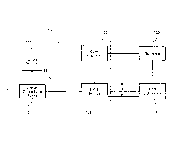
[0019] FIG. 1
illustrates a diagram of an illumination system 100 in accordance with
an embodiment of the present disclosure. The illumination system 100 may be,
for
example, a solid state lighting system including an R/G/B light source 118, a
photosensor
120, a constant current source 112, an R/G/B switch 114, and a color
controller 116. The
constant current source 112, R/G/B switch 114, and color controller 116 form a
color
control circuit or R/G/B control circuit 110 that controls the light output by
the light
source 118. The R/G/B light source 118 includes a plurality of red, green, and
blue light
emitting diodes (LEDs) (not shown). The red LEDs are electrically
interconnected to be
driven by a red input line R. The green LEDs are electrically interconnected
to be driven
by a green input line G. The blue LEDs are electrically interconnected to be
driven by
7
256081
blue input line B. The light source 118 is shown as an illustrative example
only. In
general, the light source 118 can be any multi-color light source having sets
of solid state
light sources electrically connected to define different color channels. In
some
embodiments, for example, the red, green, and blue LEDs arc arranged as red,
green and
blue LED strings. Moreover, the different colors can be other than red, green,
and blue,
and there can be more or fewer than three different colors that span a color
range less
than that of a full-color RGB light source, but including a "whitish" color
achievable by
suitable blending of the blue and yellow channels. The LEDs can be
semiconductor-
based LEDs (optionally including integral phosphor), organic LEDs (sometimes
represented in the art by the acronym OLED), semiconductor laser diodes, and
the like.
[0020] A constant
current power source 112 drives the light source 118 via a R/B/G
switch 114. The constant current power source 112 outputs a "constant current"
or
constant rms (root-mean-square) current. In some embodiments, the constant rms
current
is a constant direct current. However, the constant rms current can be a
sinusoidal
current with a constant rms value, or the like. The "constant current" is
optionally
adjustable, but should be understood that the current output by the constant
current power
source 112 is not cycled rapidly as is the case for PWM. According to one or
more
embodiments, an optional current controller 113 is provided and is configured
to
communicate with the constant current power source 112 to adjust the current
level of the
substantially constant root-mean-square drive current. The output of the
constant current
power source 112 is input to a R/B/G switch 114. The R/B/G switch 114
functions as
a demultiplexer (demux) or one-to-three switch to channel the constant current
into two
of the three color channels R, G, B at any given time. The R/B/G switch 114 of
the
present embodiment ensures that only one of the total available colors is
"off" at any
given time, i.e., only one of the three colors is "off" at any time. It should
be noted
8
CA 2890186 2017-09-22
CA 02890186 2015-05-01
WO 2014/058815
PCT/US2013/063775
that while the present embodiment has been described in terms of a three
channel switch
that ensures that two and only two colors are concurrently "on" while the
third color is
simultaneously "off', other embodiments arc envisioned that utilize different
numbers of
colors including but not limited to, for example, four and five colors without
departing
from the disclosure. In embodiments that employ four colors, three of the four
colors
will be concurrently "on" at any given time while the fourth color is
simultaneously
"off'. Similarly, in embodiments that employ five colors, four of the five
colors will be
concurrently "on" at any given time while the fifth color is simultaneously
"off'.
[0021] FIG. 2
illustrates a diagram of a timing cycle 200 for operation of the
adjustable color illumination system of FIG. 1. The timing diagram 200
provides the
basic concept of the color control achieved using the constant current power
source 112
and the R/G/B switch 114. The switching of the R/G/B switch 114 is performed
over a
time interval T that is greater than or equal to 150 Hertz. The time interval
is divided into
three time sub-intervals defined by fractional time periods Ti, T2, and T3
that correspond
to phases P1, P2, and P3, respectively. Fractional time period Ti is
represented by the
equation Ti = R1 + G1 and includes a corresponding energy measurement of El =
Ti (R1
+ G1). Fractional time period T2 is represented by the equation T2= R1 + B1
and
includes a corresponding energy measurement of E2 = T2 (G1 + B1). Fractional
time
period T3 is represented by the equation T3 = B1 + R1 and includes a
corresponding
energy measurement of E3 = T3 (B1 + R1). A color controller 116 outputs a
control
signal indicating the fractional time periods Ti x T2 x T3. For example, the
color
controller 116 may, in an illustrative embodiment, outputs a two-bit digital
signal having
9
CA 02890186 2015-05-01
WO 2014/058815
PCT/US2013/063775
value "00" indicating the fractional time period Ti, and switching to a value
"01" to
indicate the fractional time period T2, and switching to a value "10" to
indicate the
fractional time period T3, and switching back to "00" to indicate the next
occurrence of
the fractional time period Ti, and so on. In other embodiments, the control
signal can be
an analog control signal (e.g., 0 volts, 0.5 volts, and 1.0 volts indicating
the first, second,
and third fractional time periods, respectively) or can take another format.
As yet another
illustrative approach, the control signal can indicate transitions between
fractional time
periods, rather than holding a constant value indicative of each time period.
In the latter
approach, the R/G/B switch 114 is merely configured to switch from one pair of
color
channels to the next when it receives a control pulse, and the color
controller 116 outputs
a control pulse at each transition from one fractional time period to the next
fractional
time period.
[0022] Each of the
three fractional time periods Ti, T2, and T3 corresponds to two
selected color channels being concurrently "on" during that time.
Alternatively stated,
each of the three fractional time periods Ti, T2, T3 corresponds to one
selected color
channel being "off" during that time. Specifically, fractional time period Ti
corresponds
to the red color channel R1 and the green color channel G1 being "on", i.e.,
Ti = R1 +
Gl. Fractional time period T2 corresponds to the green color channel G1 and
the blue
color channel B1 being "on", i.e., T2 = G1 + Bl. Fractional time period T3
corresponds
to the blue color channel and the red color channel R1 being "on", i.e., T3 =
B1 + R1 .
During the first fractional time period Tithe R/G/B switch 114 is set to flow
the constant
current from the constant current power source 112 into two of the color
channels, i.e.,
CA 02890186 2015-05-01
WO 2014/058815
PCT/US2013/063775
into the red color channel R1 and the green color channel G1 . As a result,
the light
source 118 generates only red and green light during the first fractional time
period Ti,
i.e., the red and green lights arc maintained in the "on" state. During this
time, no power
is supplied to the blue lights and the blue lights are maintained in the "off'
state. During
the second fractional time period T2 the R/G/B switch 114 is set to flow the
constant
current from the constant current power source 112 into a second pair of the
color
channels, i.e., into the green color channel G1 and the blue color channel Bl.
As a result,
the light source 118 generates only green and blue light during the second
fractional time
period T2, i.e., the green and blue lights are maintained in the "on" state.
During this
time, no power is supplied to the red lights and the red lights are maintained
in the "off'
state. During the third fractional time period T3 the R/B/G switch 114 is set
to flow the
constant current from the constant current power source 112 into a third pair
of the color
channels, i.e., into the blue color channel B1 and the red color channel R1 .
As a result,
the light source 118 generates only blue and red light during the third
fractional time
period T3, i.e., the blue and red lights are maintained in the "on" state.
During this time,
no power is supplied to the green lights and the green lights are maintained
in the "off'
state. This cycle continues to repeat with the time period T.
[0023] The time
period T is selected to be shorter than the flicker fusion threshold,
which is defined herein as the period below which the flickering caused by the
light color
switching becomes substantially visually imperceptible, such that the light is
visually
perceived as a substantially constant blended color. That is, T is selected to
be short
enough that the human eye blends the light output during the fractional time
periods Ti,
11
CA 02890186 2015-05-01
WO 2014/058815
PCT/US2013/063775
T2, and T3 so that the human eye perceives a uniform blended color. For
example, the
period T should be below about 1/10 second, and preferably below about 1/24
second,
and more preferably below about 1/30 second, or still shorter. A lower limit
on the time
period T is imposed by the switching speed of the R/G/B switch 114, which can
be quite
fast since its operation does not entail changing current levels.
[0024] The color
can be computed quantitatively, as follows. The total energy of the
red light and green light output by the red and green LEDs during the first
fractional time
period Ti is given by El = Ti (R1 + GO. The total energy of the green light
and blue
light output by the green and blue LEDs during the second fractional time
period T2 is
given by E2 = T2 (G1 + B1). The total energy of the blue light and red light
output by the
blue and red LEDs during the third fractional time period T3 is given by E3 =
T3 (B1 +
R1). If the fractional time period had proportionality Pl:P2:P3 = 1:1:1 then
the light
output would be visually perceived as an equal blending of red, green, and
blue light,
which would produce a light output that is in the center of the gamut. The
generation of
white light is thus dependent on the choices of the LEDs and the ratios of P1
to P2 to P3.
[0025] The current
output by the constant current power source 112 into the light
source 118 remains substantially constant at all times. That is to say that
the constant
current power source 112 outputs a substantially constant current to the load
comprising
the components 114, 118.
[0026] In some
embodiments, the switching between fractional time periods
performed by the color controller 116 is done in an open-loop fashion, i.e.,
without
reliance upon optical feedback. In these embodiments, stored information,
e.g., a look-up
12
CA 02890186 2015-05-01
WO 2014/058815
PCT/US2013/063775
table, stored mathematical curves, or other stored information, associates the
values of
the fractional ratios with various colors. For example, if a 1=a2=a3 then the
values P1=
P2= P3=1/3 may be suitably associated with the "color" white.
[0027] In other
embodiments, the color is optionally controlled using optical
feedback. With further reference to FIG. 1, a photosensor 120 monitors the
light output
by the RIG/B light source 118. The photosensor 120 has a sufficiently broad
wavelength
in order to sense any of red, green, and blue light. For simplicity, it is
assumed herein
that the photosensor 120 has equal sensitivity for red, green and blue light.
However, in
embodiments where the photosensor 120 does not have equal sensitivity for red,
green,
and blue light, a suitable scaling factor may be incorporated to compensate
for spectral
sensitivity differences. The photosensor 120 measures the light output by
R/G/B light
source 118 during successive fractional time periods Ti, T2, T3. During
fractional time
period Ti, the photosensor 120 measures only red and green light, as no blue
light is
output during this time period. The photosensor 120 also generates a
measurement
output for the first color energy El during this time period. During
fractional time period
T2, the photosensor 120 measures only green and blue light, as no red light is
output
during this time period. The photosensor 120 also generates a measurement
output for
the second color energy E2 during this time period. During fractional time
period T3, the
photosensor 120 measures only blue and red light, as no green light is output
during this
time period. The photosensor 120 also generates a measurement output for the
third
color energy E3 during this time period. The photosensor 120 is capable of
generating all
13
CA 02890186 2015-05-01
WO 2014/058815
PCT/US2013/063775
three of the measured first color energy El, the measured second color energy
E2, and
the measured third color energy E3.
[0028] Instead of
measuring one color at a time for a specified time duration, the
R/G/B control circuit 110 ensures that two and only two sets of LEDs of
different colors
are energized to be operational ("on") at any given time. Utilizing two sets
of operational
("on") LEDs of different colors at a time allows the color controller 116 to
calculate the
color output and changes in the color output of each color phase by varying
the -off' time
of the third set of LEDs, and then deducing the light output by subtraction.
This allows
the system to stabilize and compensate for the small color-shifting that
occurs in the
LEDs over time due to degradation and the like. Utilizing two sets of
concurrently
operational ("on") LEDs allows the system to produce a white light with far
fewer LEDs
and more even spectral distribution of color when compared to systems that
utilize only
one set of operational ("on") LEDs at a time, thereby providing a more
efficient and
economical system. Further, utilizing two sets of concurrently operational
("on") LEDs
also allows for more rapid and accurate correction of color-shifting due to
degradation
and the like, thereby producing superior color rendering and providing the
ability to track
color to maintain a color temperature within one ellipse over the life of the
system.
[0029] The color
controller 116 uses the measured color energies El, E2, E3 to
provide feedback color control. In operation, the photosensor 120 measures
various light
outputs from the light source 118 in rapid sequence, i.e., at a rate that a
person cannot
perceive changes in light intensity due to inherent human persistence of
vision. The
photosensor 120 measures the change in light output for each pair of LED
channels. The
14
CA 02890186 2015-05-01
WO 2014/058815
PCT/US2013/063775
color controller 116 uses the output information and compares it to a baseline
to deduce
the light output of that particular set of LEDs. For example, the color
controller 116 may
utilize an algorithm to calculate the light output for each pair of LEDs of
the R/G/B light
source 118. Since two pairs of LEDs or sources are on simultaneously, the
system
utilizes subtraction to determine the light output for each pair of LEDs.
[0030] Assuming that P1, P2, and P3 correspond to photosensor measurements
during Ti, T2, and T3, respectively (i.e., P1 = photo sensor during Ti; P2 =
photo sensor
during T2; and P3 = photo sensor during T3), calculation of the energy output
for each of
the red, green, and blue sets of LEDs is respectively provided by the
following:
R (T1) = (P1 + P3 ¨ P2) / 2 (1)
G (T2) = (P2 + P1 ¨ P3) / 2 (2)
B (T3) = (P3 + P2 ¨ P1) / 2 (3)
[0031] FIG. 3 illustrates a calculation loop 300 for the process utilized
by the system
of the present disclosure to determine the energy of each set of LEDs, as
discussed above.
The calculation loop 300 begins at 302. At 302, the system measures PI, P2, P3
for each
fractional time period Ti, T2, T3. At 304, the system calculates the
corresponding
energy output ER, EG, EB for each individual set of red light, green light,
and blue light,
respectively. At 306, the system compares the calculated energy outputs to set
point
values (or to the last calculated output values). At 308, the system
determines whether
the energy output for red light is less than the set point value, i.e.,
whether ER is less than
ERSET. When ER < ERSET, the system increases both Ti and T3 by 1 or (Ti + 1;
T3 +
1), and decreases T2 by 2 or (T2 ¨ 2). At 310, the system determines whether
the energy
CA 02890186 2015-05-01
WO 2014/058815
PCT/US2013/063775
output for green light is less than the set point value, i.e., whether EG is
less than EGSET.
When EG < EGSET, the system increases both T2 and Ti by 1 or (T2 + 1; Ti + 1),
and
decreases T3 by 2 or (T3 ¨ 2). At 312, the system determines whether the
energy output
for blue light is less than the set point value, i.e., whether EB is less than
EBSET. When
EB < EBSET, the system increases both T3 and T2 by 1 or (T3 + 1; T2 + 1). At
314, the
system outputs the calculated times to the R/G/B control circuit 110. The
calculation
loop 300 is continually repeated in order to update the calculations such that
the color
controller 116 can vary the output of the sets of LEDs to compensate for light
output
variations in the LEDs due to, for example, color-shifting, degradation and
the like.
[0032] The term
"color" as used herein is to be broadly construed as any visually
perceptible color. The term -color" is to be construed as including white, and
is not to be
construed as limited to primary colors. The term "color" may refer to, for
example, an
LED that outputs two or more distinct spectral peaks (for example, an LED
package
including red and yellow LEDs to achieve an orange-like color having distinct
red and
yellow spectral peaks). The term "color" may also refer to, for example, an
LED that
outputs a broad spectrum of light, such as an LED package including a
broadband
phosphor that is excited by electroluminescence from a semiconductor chip. An
"adjustable color light source" as used herein is to be broadly construed as
any light
source that can selectively output light of different spectra. An adjustable
color light
source is not limited to a light source providing full color selection. For
example, in
some embodiments an adjustable color light source may provide only white
light, but the
16
CA 02890186 2015-05-01
WO 2014/058815
PCT/US2013/063775
white light is adjustable in terms of color temperature, color rendering
characteristics, and
the like.
[0033] FIG. 4
illustrates a schematic of an adjustable color light source 400 in
accordance with an embodiment of the present disclosure. The adjustable color
light
source 400 includes a set of three series-connected strings Si, S2, S3 of five
LEDs each.
The first string Si includes five LEDs emitting at a peak wavelength of about
617 nm,
corresponding to a shallow red. The second string S2 includes five LEDs
emitting at 530
nm, corresponding to green. The third string S3 includes five LEDs emitting at
a peak
wavelength of about 455 nm, corresponding to blue. Drive and control circuitry
includes
a constant current source CC and three conducting transistors with inputs R1,
Gl, B1
arranged to drive current flow through the first, second, and third LED
strings Si, S2, S3,
respectively. An operational state table for the adjustable color light source
of FIG. 4 is
listed below in Table 1.
TABLE 1
Fractional Conducting Channel Illumination Channel
Time Transistors Peak Wavelength(s) Colors
Period (Qualitative)
Ti R1 and G1 617 nm and 530 nm Red and Green
T2 G1 and B1 530 nm and 455 nm Green and Blue
T3 B1 and R1 455 nm and 617 nm Blue and Red
[0034] While the
present embodiment discloses a set of three series-connected
strings of five LEDs each, other embodiments are contemplated without
departing from
17
CA 02890186 2015-05-01
WO 2014/058815
PCT/US2013/063775
the disclosure. The set of LEDs may be of a number other than three and may
include,
for example, four or five strings of LEDs of different colors. In each
embodiment, the
control circuit 110 operates to maintain one and only one string of LEDs in
the "off' state
at any time while all other strings of LEDs are concurrently in the
operational or "on"
state. Similarly, while the present embodiment discloses five LEDs per string,
the
number of LEDs may be selected based on the use and technical requires of the
adjustable color light source, e.g., desired light output and the like.
Therefore, each string
may include any number of LEDs without departing from the disclosure. Further,
while
LEDs of particular wavelengths are disclosed herein these wavelengths have
been
selected for simplicity (e.g., to fall within the ranges of red light, green
light, and blue
light, respectively) and should not be deemed as limiting. LEDs of varying
wavelengths
may be utilized without departing from the disclosure. Further still, each
string of LEDs
may also include LEDs of different wavelengths, e.g., multiple LED within the
same or
similar color range, without departing from the disclosure.
[0035] Referring
further to FIG. 2, the timing cycle 200 also plots the diagram for
operation of the adjustable color illumination system of FIG. 4. It is noted
that the LED
wavelengths or colors of the adjustable color illumination system of FIG. 4
are not
selected to provide adjustable full-color illumination, but rather are
selected to provide
white light of varying quality including, for example, warm white light
(biased toward
the red) or cold white light (biased toward the blue). The adjustable color
illumination
system of FIG. 4 has three color channels, as labeled in Table 1. The three
transistors are
operated to provide a two-of-three switch operating over a time interval T,
which in FIG.
18
CA 02890186 2015-05-01
WO 2014/058815
PCT/US2013/063775
2 is 1/150 sec (6.67 ms) in accordance with a selected time division of the
time interval T
to generate white light with selected quality or characteristics. The time
interval T=1/150
sec is shorter than the flicker fusion threshold for a typical viewer. The
time interval T is
time-division multiplexed into three fractional time periods Ti, T2, T3 where
the three
fractional time periods are non-overlapping and sum to the time interval T,
that is T = Ti
+ T2 + T3. In the embodiment of FIG. 2, the energy measurement for each pair
of color
channels associated with the respective fractional time periods is acquired at
an
intermediate time substantially centered within each fractional time period,
as indicated
by the arrows and energy measurement notations El, E2, E3 indicating the
operating
wavelengths at each color energy measurement. Fractional time period Ti is
represented
by the equation Ti = R1 + G1 and includes a corresponding energy measurement
of El =
Ti (R1 + G1). Fractional time period T2 is represented by the equation T2 = R1
+ B1 and
includes a corresponding energy measurement of E2 = T2 (G1 + B1). Fractional
time
period T3 is represented by the equation T3 = B1 + R1 and includes a
corresponding
energy measurement of E3 = T3 (Bl + R1).
[0036] FIG. 5
illustrates a control process for operation of the adjustable color
illumination system including three transistors, as discussed above with
respect to FIG. 4.
The control process 500 starts, at 502, by loading existing time values for
the fractional
time periods Ti, T2, T3 into a controller. At 504, 506, 508 successive
operations are
initiated for the three fractional time periods Ti, T2, T3 during which a
single
photosensor performs respective energy measurements. At 510, a calculation
block uses
the measurements to compute updated values for the fractional time periods Tl,
T2, T3.
19
CA 02890186 2015-05-01
WO 2014/058815
PCT/US2013/063775
For example, the relationship [El x Ti] / [E2 x T2] = C12 wherein C12 is a
constant
reflecting the desired red-green/green-blue color ratio is suitably used to
constrain the
fractional time periods Ti and T2; the relationship [E2 x T2] / [E3 x T3] =
C23 where C23
is a constant reflecting the desired green-blue/blue-red color ratio is
suitably used to
constrain the fractional time periods T2 and T3; and the relationship [E3 x
T3] / [El x
T 1] = C31 where C31 is a constant reflecting the desired blue-red/red-green
color ratio is
suitably used to constrain the fractional time periods T3 and Ti. The
calculation block
suitably simultaneously solves these three equations along with the
constraints T = T1 +
T2 + T3 to obtain the updated values for the fractional time periods Ti, T2,
T3. In some
embodiments, the calculation block operates in the background in an
asynchronous
manner respective to the cycling of the light source at time interval T. At
520, to
accommodate such asynchronous operation, a decision block monitors the
calculation
block and determines whether the timing calculations are done. If "No", the
timing
calculations are loaded at 502. If "Yes", the new timing values are loaded at
522 and
input at 504. The control process 500 is continually repeated, i.e., loops, in
order to
measure the energy output by the sets of LEDs such that new timing values can
be
computed to suitably control the fractional time periods Ti, T2, T3 associated
with each
of the phases Pi, P2, and P3, respectively.
[0037] Alternative
embodiments, examples, and modifications which would still be
encompassed by the disclosure may be made by those skilled in the art,
particularly in
light of the foregoing teachings. Further, it should be understood that the
terminology
256081
used to describe the disclosure is intended to be in the nature of words of
description
rather than of limitation.
[0038] Those
skilled in the art will also appreciate that various adaptations and
modifications of the preferred and alternative embodiments described above can
be
configured without departing from the scope of the disclosure. Therefore, it
is to be
understood that, within the scope of the appended claims, the disclosure may
be practiced
other than as specifically described herein.
21
CA 2890186 2017-09-22