Language selection

Search

Patent 2890883 Summary

Third-party information liability

Some of the information on this Web page has been provided by external sources. The Government of Canada is not responsible for the accuracy, reliability or currency of the information supplied by external sources. Users wishing to rely upon this information should consult directly with the source of the information. Content provided by external sources is not subject to official languages, privacy and accessibility requirements.

Claims and Abstract availability

Any discrepancies in the text and image of the Claims and Abstract are due to differing posting times. Text of the Claims and Abstract are posted:

  • At the time the application is open to public inspection;
  • At the time of issue of the patent (grant).
(12) Patent: (11) CA 2890883
(54) English Title: DISSOLVABLE TOOL AND METHOD OF DISSOLVING SAME
(54) French Title: OUTIL SOLUBLE ET PROCEDE DE DISSOLUTION DE CELUI-CI
Status: Granted and Issued
Bibliographic Data
(51) International Patent Classification (IPC):
  • E21B 34/06 (2006.01)
  • E21B 33/124 (2006.01)
  • E21B 34/14 (2006.01)
(72) Inventors :
  • MAILAND, JASON C. (United States of America)
  • JOHNSON, CHARLES C. (United States of America)
  • KITZMAN, JEFFERY D. (United States of America)
(73) Owners :
  • BAKER HUGHES INCORPORATED
(71) Applicants :
  • BAKER HUGHES INCORPORATED (United States of America)
(74) Agent: MARKS & CLERK
(74) Associate agent:
(45) Issued: 2017-09-19
(86) PCT Filing Date: 2013-11-01
(87) Open to Public Inspection: 2014-05-15
Examination requested: 2015-05-05
Availability of licence: N/A
Dedicated to the Public: N/A
(25) Language of filing: English

Patent Cooperation Treaty (PCT): Yes
(86) PCT Filing Number: PCT/US2013/068070
(87) International Publication Number: US2013068070
(85) National Entry: 2015-05-05

(30) Application Priority Data:
Application No. Country/Territory Date
13/670,902 (United States of America) 2012-11-07

Abstracts

English Abstract

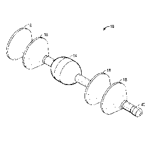
A dissolvable tool includes a body having at least a portion configured to dissolve in a fluid, and a barrier connected to the body. The barrier is configured to slidably fluidically seal to a structure that the body and the barrier are movable within to maintain a volume of the fluid between the barrier and the body while the barrier and the body are moved through the structure.


French Abstract

L'invention concerne un outil soluble comprenant un corps ayant au moins une partie conçue pour se dissoudre dans un fluide, et une barrière reliée au corps. La barrière est conçue pour se sceller de manière coulissante du point de vue des fluides à une structure au sein de laquelle le corps et la barrière sont mobiles pour maintenir un volume du fluide entre la barrière et le corps tandis que la barrière et le corps sont déplacés à travers la structure.

Claims

Note: Claims are shown in the official language in which they were submitted.


What is claimed is:
1. A dissolvable tool comprising:
a body having at least a portion configured to dissolve in a known fluid; and
at least one barrier connected to the body configured to slidably fluidically
seal to a
structure that the body and the at least one barrier are movable within to
maintain a known
volume of the known fluid between the at least one barrier and the body while
the at least one
barrier and the body are moved through the structure.
2. The dissolvable tool of claim 1, wherein the structure is in a borehole
in an earth
formation.
3. The dissolvable tool of claim 1 or 2, wherein the body is configured to
slidably
sealably engage to the structure as it moves therethrough.
4. The dissolvable tool of any one of claims 1 to 3, wherein the at least
one barrier is
dissolvable in the fluid.
5. The dissolvable tool of any one of claims 1 to 4, wherein the at least
one barrier has a
frustoconical shape.
6. The dissolvable tool of any one of claims 1 to 4, wherein the at least
one barrier is two
barriers and each of the two barriers is located on an opposing side of the
body from one
another.
7. The dissolvable tool of any one of claims 1 to 4, wherein the at least
one barrier is
flexible to allow it to deform while passing through localized dimensional
reductions in an
inner dimension of the structure.
8. The dissolvable tool of any one of claims 1 to 4, wherein the at least
one barrier is
releasably attachable to the body.
9. The dissolvable tool of any one of claims 1 to 4, wherein the at least
one barrier is
releasable attachable to others of the at least one barrier.

10. The dissolvable tool of any one of claims 1 to 9, wherein the at least
a portion of the
body has a partially spherical shape.
11. The dissolvable tool of any one of claims 1 to 10, wherein the body is
a plug capable of
seating against a seat and allowing pressure built there against to actuate
another tool or treat an
earth formation.
12. The dissolvable tool of any one of claims 1 to 11, wherein the volume
is selected to be
sufficient to completely dissolve the body.
13. The dissolvable tool of any one of claims 1 to 12, further comprising a
spacer
configured to connect between the body and the at least one barrier to allow
for alterations in
the volume.
14. The dissolvable tool of any one of claims 1 to 13, further comprising a
nose piece
configured to attached to at least one of the body and the at least one
barrier to resist hanging
up of the dissolvable tool as it is moved through the structure.
15. The dissolvable tool of any one of claims 1 to 14, wherein the body is
hollow.
16. The dissolvable tool of any one of claims 1 to 15, wherein the at least
one barrier is
substantially non-dissolvable in the fluid.
17. A method comprising:
positioning a fluid configured to dissolve a body of the tool within a
structure;
positioning the body and at least one barrier attached thereto within the
structure such
that at least a portion of the fluid is positioned between the body and the at
least one barrier;
running the body and the at least one barrier through the structure; and
maintaining the fluid between the body and the at least one barrier.
18. The method of dissolving a tool of claim 17, further comprising
dissolving at least a
portion of the body with the fluid.
6

19. The method of dissolving a tool of claim 17 or 18, further comprising
slidably sealing
the at least one barrier to the structure.
20. The method of dissolving a tool of claim 17 or 18, further comprising
slidably sealing
the body to the structure.
21. The method of dissolving a tool of any one of claims 17 to 20, further
comprising
positioning a second of the at least one barrier to the body on a side
opposite that of the first of
the at least one barrier.
22. The method of dissolving a tool of claim 21, further comprising
maintaining the fluid
between the two at least one barriers.
7

Description

Note: Descriptions are shown in the official language in which they were submitted.


CA 02890883 2016-09-14
DISSOLVABLE TOOL AND METHOD OF DISSOLVING SAME
BACKGROUND
[0001] Temporarily plugging passageways through tubular systems allows
operators to
build pressure against the temporary plug to perform an operation. For
example, the
hydrocarbon recovery and carbon dioxide sequestration industries employ
temporary plugs in
earth formation boreholes to actuate valves, to fracture earth formations and
to pump
proppant or acid into earth formations. After the usefulness of the pluggage
is complete it is
often desirable to remove the pluggage. Intervention to drill or mill out the
plug is one
method commonly employed, however the time and equipment required for such
intervention
may be undesirable. Dissolvable plugs have been developed that do not require
an
intervention and many work well for their intended purpose. The industry is
however, always
interested in new systems and methods to improve the art of temporarily
plugging tubular
passageways.
BRIEF DESCRIPTION
[0002] Accordingly, in one aspect there is provided a dissolvable tool
comprising: a
body having at least a portion configured to dissolve in a known fluid; and at
least one barrier
connected to the body configured to slidably fluidically seal to a structure
that the body and the
at least one barrier are movable within to maintain a known volume of the
known fluid between
the at least one barrier and the body while the at least one barrier and the
body are moved
through the structure.
[0002a] According to another aspect there is provided a method comprising:
positioning a fluid configured to dissolve a body of the tool within a
structure; positioning the
body and at least one barrier attached thereto within the structure such that
at least a portion of
the fluid is positioned between the body and the at least one barrier; running
the body and the at
least one barrier through the structure; and maintaining the fluid between the
body and the at
least one barrier.
1

CA 02890883 2015-05-05
WO 2014/074412 PCT/US2013/068070
BRIEF DESCRIPTION OF THE DRAWINGS
[0003] The following descriptions should not be considered limiting in any
way.
With reference to the accompanying drawings, like elements are numbered alike:
[0004] FIG. 1 depicts a perspective view of an embodiment of a dissolvable
tool
disclosed herein;
[0005] FIG. 2 depicts a cross sectional view of the dissolvable tool of FIG.
1;
[0006] FIG. 3 depicts a cross sectional view of the dissolvable tool of FIG. 1
positioned within a structure; and
[0007] FIG. 4 depicts a cross sectional view of an alternate body employable
in a
dissolvable tool disclosed herein.
DETAILED DESCRIPTION
[0008] A detailed description of one or more embodiments of the disclosed
apparatus
and method are presented herein by way of exemplification and not limitation
with reference
to the Figures.
[0009] Referring to Figure 1-3, an embodiment of a dissolvable tool disclosed
herein
is illustrated at 10. The dissolvable tool 10 includes a body 14 and at least
one barrier 18,
with four of the barriers 18 being shown in the Figures. The dissolvable tool
10 is movable
within a structure 22, illustrated herein as a casing or drill string in a
borehole in an earth
formation (Figure 3), such as a wellbore as is commonly used in the oil and
gas recovery
industry, for example, or a borehole in the carbon dioxide sequestration
industry. The
barriers 18 are configured to slidable sealingly engage with interior walls 26
of the structure
22 while moving therethrough. This sealing maintains a volume 30 of a fluid 34
in positional
relationship to the barrier 18 and the body 14 while the tool 10 is moved
through the structure
22. The body 14 is made of a material dissolvable in the fluid 34. One example
of such a
material is disclosed in U.S. Patent Application Number 12/633,686 assigned to
the same
assignee as this application and filed on 12/08/2009, the entire contents of
which are
incorporated herein by reference.
[0010] By maintaining the known volume 30 of the known fluid 34 the
dissolvable
tool 10 is a reliable and dependable configuration that provides predictable
timing to dissolve
the tool 10. This reliability avoids expensive downtime associated with
unpredictable
dissolving times of typical systems that rely on downhole fluid alone, or
fluid pumped
downhole but not sealably separated from existing downhole fluid, to dissolve
a tool.
2

CA 02890883 2015-05-05
WO 2014/074412 PCT/US2013/068070
[0 0 1 1] The dissolvable tool 10 as illustrated is constructed to allow for
simple
detachment and reattachment of the barriers 18 to the body 14. This
configurability allows an
operator to customize the tool 10 for each particular application. Such
customization
includes varying the number of barriers 18 positioned to either side of the
body 14 as well as
altering the volume 30 through use of differently sized spacers 38 that are
positionable
between adjacent barriers 18 or between a barrier 18 and the body 14. The
spacers 38 can
attach to the barriers 18 and the body 14 via the same attachment means
employed between
the barriers and the body 14 directly. One such common attachment means
includes
threadable engagement between components, for example. Altering the volume 30
may be
desirable to further control the rate of dissolution of the body 14 within the
fluid 34 as well as
to assure that there is an adequate amount of the fluid 34 to fully dissolve
the body 14. An
optional nose piece 40 may be attached to one of the barriers 18 or to a
spacer 38 attached to
one of the barriers 18 or the body 14 directly to minimize hanging up of the
tool 10 as it is
run through the structure 22.
[0012] The barriers 18 can be made of the same materials as the body 14
thereby
being dissolvable in the fluid 34 as well, or can be of an alternate material
that is substantially
non-dissolvable in the fluid 34. Regardless of the material employed, the
barriers 18 may be
configured to flex to allow a largest radial dimension thereof to remain in
continuous contact
with the interior walls 26 of the structure 22 while being run therethrough.
This flexibility
can allow the barriers 18 to pass through areas 42 of the structure 22 having
a locally reduced
radial dimension 46 without the tool 10 becoming stuck. The barriers 18 of the
illustrated
embodiment have a frustoconical shape when nondeformed as shown in Figures 1
and 2, and
have a curved funnel shape when deformed as shown in Figure 3. It should be
noted that
alternate barrier shapes are also employable such as disk shaped, spherical
and oval, for
example.
[0013] The reduced radial dimension 46 of the areas 42 may include a seat 50
configured to be seatingly engaged by the body 14 to temporarily plug the
structure 22. The
body 14 may have a spherical shape 54 at least on one end 58 to facilitate
seatingly engaging
with the seat 50. As such, the body 14 while seated at the seat 50 can allow
pressure to build
thereagainst to perform an operation, such as actuating another tool (not
shown) or fracturing
or treating an earth formation, for example. Once the body 14 has sufficiently
dissolved and
its largest radial dimensions reduced it can be pumped through the seat 50
thereby removing
the plug without requiring an intervention and the downtime associated
therewith. It should
be noted that the body 14 may be sized to effectively slidably sealingly
engage with the inner
3

CA 02890883 2015-05-05
WO 2014/074412 PCT/US2013/068070
radial walls 26 of the structure 22 in locations other than areas 42 with the
seat 50. Such a
seal can aid in maintaining the fluid 34 between the barrier 18 and the body
14 thereby
avoiding diluting the fluid 34 with other downhole fluids.
[0014] Referring to Figure 4, an alternate embodiment of a body 114 usable in
the
tool 10 is illustrated. The body 114 differs from the body 14 in that only a
portion 160, that
surrounds a core 164, is dissolvable in the fluid 34. By locating the portion
160 at the largest
radial dimension only of the body 114 a sufficient reduction in size of the
body 114 will
occur to allow the body 114 to pass through the seat 50 after dissolving has
occurred. Other
alternate embodiments of a body of the tool 10 are also contemplated. For
example, a body
could be hollow such that only a shell thereof is made of a solid dissolvable
material while
the inside is filled with a fluid.
[0015] While the invention has been described with reference to an exemplary
embodiment or embodiments, it will be understood by those skilled in the art
that various
changes may be made and equivalents may be substituted for elements thereof
without
departing from the scope of the invention. In addition, many modifications may
be made to
adapt a particular situation or material to the teachings of the invention
without departing
from the essential scope thereof. Therefore, it is intended that the invention
not be limited to
the particular embodiment disclosed as the best mode contemplated for carrying
out this
invention, but that the invention will include all embodiments falling within
the scope of the
claims. Also, in the drawings and the description, there have been disclosed
exemplary
embodiments of the invention and, although specific terms may have been
employed, they
are unless otherwise stated used in a generic and descriptive sense only and
not for purposes
of limitation, the scope of the invention therefore not being so limited.
Moreover, the use of
the terms first, second, etc. do not denote any order or importance, but
rather the terms first,
second, etc. are used to distinguish one element from another. Furthermore,
the use of the
terms a, an, etc. do not denote a limitation of quantity, but rather denote
the presence of at
least one of the referenced item.
4

Representative Drawing
A single figure which represents the drawing illustrating the invention.
Administrative Status

2024-08-01:As part of the Next Generation Patents (NGP) transition, the Canadian Patents Database (CPD) now contains a more detailed Event History, which replicates the Event Log of our new back-office solution.

Please note that "Inactive:" events refers to events no longer in use in our new back-office solution.

For a clearer understanding of the status of the application/patent presented on this page, the site Disclaimer , as well as the definitions for Patent , Event History , Maintenance Fee  and Payment History  should be consulted.

Event History

Description Date
Common Representative Appointed 2019-10-30
Grant by Issuance 2017-09-19
Inactive: Cover page published 2017-09-18
Inactive: Final fee received 2017-08-03
Pre-grant 2017-08-03
Notice of Allowance is Issued 2017-02-10
Letter Sent 2017-02-10
Notice of Allowance is Issued 2017-02-10
Inactive: Q2 passed 2017-02-06
Inactive: Approved for allowance (AFA) 2017-02-06
Amendment Received - Voluntary Amendment 2016-09-14
Inactive: S.30(2) Rules - Examiner requisition 2016-03-21
Inactive: Report - No QC 2016-03-17
Inactive: Cover page published 2015-05-29
Inactive: Acknowledgment of national entry - RFE 2015-05-14
Inactive: IPC assigned 2015-05-14
Application Received - PCT 2015-05-14
Inactive: First IPC assigned 2015-05-14
Letter Sent 2015-05-14
National Entry Requirements Determined Compliant 2015-05-05
Request for Examination Requirements Determined Compliant 2015-05-05
All Requirements for Examination Determined Compliant 2015-05-05
Application Published (Open to Public Inspection) 2014-05-15

Abandonment History

There is no abandonment history.

Maintenance Fee

The last payment was received on 2016-10-07

Note : If the full payment has not been received on or before the date indicated, a further fee may be required which may be one of the following

  • the reinstatement fee;
  • the late payment fee; or
  • additional fee to reverse deemed expiry.

Patent fees are adjusted on the 1st of January every year. The amounts above are the current amounts if received by December 31 of the current year.
Please refer to the CIPO Patent Fees web page to see all current fee amounts.

Fee History

Fee Type Anniversary Year Due Date Paid Date
MF (application, 2nd anniv.) - standard 02 2015-11-02 2015-05-05
Request for examination - standard 2015-05-05
Basic national fee - standard 2015-05-05
MF (application, 3rd anniv.) - standard 03 2016-11-01 2016-10-07
Final fee - standard 2017-08-03
MF (patent, 4th anniv.) - standard 2017-11-01 2017-10-06
MF (patent, 5th anniv.) - standard 2018-11-01 2018-10-11
MF (patent, 6th anniv.) - standard 2019-11-01 2019-10-22
MF (patent, 7th anniv.) - standard 2020-11-02 2020-10-21
MF (patent, 8th anniv.) - standard 2021-11-01 2021-10-20
MF (patent, 9th anniv.) - standard 2022-11-01 2022-10-24
MF (patent, 10th anniv.) - standard 2023-11-01 2023-10-19
Owners on Record

Note: Records showing the ownership history in alphabetical order.

Current Owners on Record
BAKER HUGHES INCORPORATED
Past Owners on Record
CHARLES C. JOHNSON
JASON C. MAILAND
JEFFERY D. KITZMAN
Past Owners that do not appear in the "Owners on Record" listing will appear in other documentation within the application.
Documents

To view selected files, please enter reCAPTCHA code :


To view images, click a link in the Document Description column. To download the documents, select one or more checkboxes in the first column and then click the "Download Selected in PDF format (Zip Archive)" or the "Download Selected as Single PDF" button.

List of published and non-published patent-specific documents on the CPD .

If you have any difficulty accessing content, you can call the Client Service Centre at 1-866-997-1936 or send them an e-mail at CIPO Client Service Centre.


Document
Description 
Date
(yyyy-mm-dd) 
Number of pages   Size of Image (KB) 
Abstract 2015-05-04 2 68
Description 2015-05-04 4 221
Representative drawing 2015-05-04 1 20
Claims 2015-05-04 2 80
Drawings 2015-05-04 3 109
Description 2016-09-13 4 214
Claims 2016-09-13 3 80
Representative drawing 2017-08-20 1 10
Acknowledgement of Request for Examination 2015-05-13 1 174
Notice of National Entry 2015-05-13 1 201
Commissioner's Notice - Application Found Allowable 2017-02-09 1 162
PCT 2015-05-04 14 515
Examiner Requisition 2016-03-20 4 244
Amendment / response to report 2016-09-13 7 233
Final fee 2017-08-02 2 69