Language selection

Search

Patent 2891165 Summary

Third-party information liability

Some of the information on this Web page has been provided by external sources. The Government of Canada is not responsible for the accuracy, reliability or currency of the information supplied by external sources. Users wishing to rely upon this information should consult directly with the source of the information. Content provided by external sources is not subject to official languages, privacy and accessibility requirements.

Claims and Abstract availability

Any discrepancies in the text and image of the Claims and Abstract are due to differing posting times. Text of the Claims and Abstract are posted:

  • At the time the application is open to public inspection;
  • At the time of issue of the patent (grant).
(12) Patent Application: (11) CA 2891165
(54) English Title: LIGHTING ASSEMBLY, SYSTEM AND INSTALLATION METHOD FOR HARDSCAPES AND STEPS
(54) French Title: DISPOSITIF D'ECLAIRAGE, SYSTEME ET METHODE D'INSTALLATION DANS LES MATERIAUX INERTES ET LES MARCHES
Status: Deemed Abandoned and Beyond the Period of Reinstatement - Pending Response to Notice of Disregarded Communication
Bibliographic Data
(51) International Patent Classification (IPC):
  • F21V 23/06 (2006.01)
  • F21K 9/00 (2016.01)
  • F21V 15/01 (2006.01)
  • F21V 21/02 (2006.01)
  • H05B 45/37 (2020.01)
(72) Inventors :
  • FREILL, PETER E. (Canada)
(73) Owners :
  • PETER E. FREILL
(71) Applicants :
  • PETER E. FREILL (Canada)
(74) Agent:
(74) Associate agent:
(45) Issued:
(22) Filed Date: 2015-05-14
(41) Open to Public Inspection: 2016-11-14
Availability of licence: N/A
Dedicated to the Public: N/A
(25) Language of filing: English

Patent Cooperation Treaty (PCT): No

(30) Application Priority Data: None

Abstracts

English Abstract


An outdoor lighting assembly, system and installation method for hardscapes
and steps using
network cables to supply power to a plurality of lighting assemblies is
disclosed. The lighting
assembly contains a LED, a voltage conversion circuit and two RJ45 connectors.
Power is delivered
from network cables carrying low voltage power.


Claims

Note: Claims are shown in the official language in which they were submitted.

1
Claims
What is claimed is:
1. A lighting assembly comprising:
two RJ45 connectors;
voltage conversion circuit and protective housing;
thin circuit board; and
a LED.
2. A lighting assembly according to claim 1, further comprising RJ45 pins
defined as pins 4 and/or
positive low voltage with respect to pins 7 and/or 8 as return.
3. A lighting assembly according to claim 1, further comprising of a
protective material to repel
water and surrounding materials.
4. A lighting assembly according to claim 1, further comprising a thin
printed circuit card to fit
between elements of such items as hardscapes or steps.
5. A lighting assembly according to claim 1, further comprising an
installation method into steps.
6. A lighting assembly according to claim 1, further comprising the use of
network cables to
provide power to a plurality of said lighting assemblies.
7. A lighting assembly according to claim 1, further comprising an
installation method into
hardscapes between the supporting structure and the above cap.
8. An installation method according to claim 7, further comprising a final
installation where no part
of lighting assembly of claim 1 is readily visible.

Description

Note: Descriptions are shown in the official language in which they were submitted.


CA 02891165 2015-05-14
1
Description:
Field of the Invention
This invention relates to a lighting assembly, system and installation method
lighting for
hardscapes and steps.
Background Art:
Most patents in this field address mechanical housings that provide ease of
use such as CA
2654119 or are of a novel construction to improve installation and maintenance
such as CA
2661412. All patents addressing landscape or hardscape feature a specific
housing that is either
powered by AC mains power such as 120VAC to 240VAC, a safe low voltage as
derived from the AC
mains power such as 12VDC or, in some cases, solar power.
The mechanical features of all patents in this field resemble a housing that
is visible after the final
installation. This detracts from the beauty and simplicity of hardscape walls
and steps. A form of
LED lighting whose housing that cannot be seen and is hidden in a hardscape
wall or under steps is
aesthetically pleasing and therefore highly desirable.
The connection of the power source to all patented outdoor LED lights is
either not addressed or is
made via various wires of different compositions and terminated with various
connectors. The
wires are often not as rugged as they should be and splicing or adding extra
lengths of wire can be
onerous for typical landscape installers.
This patent introduces two cost effective ways of providing outdoor LED
lighting that has not been
addressed in any earlier patents. The first is the mechanical features of the
lighting assembly,
which converts the low voltage power into light, where the housing is hidden
in the supporting
structure. The second is the means of providing power to said lighting
assembly via industry
standard network cables.

CA 02891165 2015-05-14
2
Summary of Invention:
The lighting assembly of this invention comprises a circuit card consisting of
two RJ45 connector
jacks and voltage conversion circuit enclosed in a protective housing at one
end, with a LED light at
the other end.
The circuit card of the lighting assembly is thin enough to be conspicuous
when installed but strong
enough to withstand the weight of a hardscape cap material on top while being
supported by a
hardscape block underneath. With minor adjustments, the lighting assembly can
be installed in
steps as well. The lighting assembly provides current limited power via the
voltage conversion
circuit to the LED light. The resulting light is projected downward.
The two RJ45 connector jacks share common pin connections to provide power to
the lighting
assembly, which simultaneously facilitates a daisy-chain power connection to a
plurality of lighting
assemblies in the system. Power is provided by network cables that are
terminated with the
matching RJ45 connector plugs.
Brief Description of the Drawings
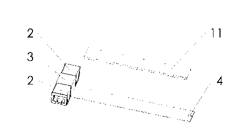
Figure 1 is a perspective drawing of the lighting assembly of this invention.
Figure 2 is a drawing of a wiring system of this invention.
Figure 3a and figure 3b are perspective sectional drawings of the lighting
assembly installed in a
hardscape walls.
Figure 4 is a perspective drawing of the lighting assembly installed in steps.
Figure 5 is a prospective drawing of a network cable.

CA 02891165 2015-05-14
3
Detailed Description of the Invention
The lighting assembly [1] of this invention comprises a circuit card
consisting of two RJ45 connector
jacks [2] and voltage conversion circuit enclosed in a protective housing [3]
at one end and a LED
light [4] at the other end. A RJ45 connector is defined herein as the IEC
60603-7 8P8C modular
connector with eight conductors.
The RJ45 connector jacks [2] use pins 4 and/or 5 for positive DC power; pins 7
and/or 8 for return.
This pin numbering is per definition of Power over Ethernet (PoE) 802.3af mode
B. Power can be
supplied to either RJ45 connector jacks. If no further lighting assemblies are
required, the second
RJ45 connector [2] is left unconnected.
The lighting assembly [1] circuit card may be made of, for example, FR-4
material, is constructed
thin enough that its presence does not cause a noticeable change in height of
the cap [8] or step
[9] installed above said lighting assembly. If a small adjustment in cap or
step height is required, a
spacer [11], made of surplus circuit board material, is provided. The
conductors in the circuit card
of the lighting assembly [1] are buried to avoid damage from the supporting
elements. The lighting
assembly [1] uses various means to displace water to ensure it maintains its
function by adding a
protective coating on the circuit board and water displacement material place
in the connectors.
The LED light [4] may be, for example, a warm white LED.
Figure 2 illustrates the connection of power to the lighting assembly [1].
Providing power to the
lighting assembly is done via a plurality of network cables [6]. The network
cables [6] contain 8
solid conductors and may be, for example, category 5, 5e or 6 according to
ANSI/TIA/EIA-568.
Figure 5 is a prospective illustration of a network cable [6]. These cables
are terminated with RJ45
connector plugs [12] as each end. Both plugs share the same pin numbering and
conductor
mapping.

CA 02891165 2015-05-14
4
The method of injecting power into the network cable may be, for example, an
indoor power
injector [5] with a matching power source. The power source may be, for
example, a wall mount
adapter [13]. Power may be, for example, 12VDC.
Figures 3a and 3b provide prospective sectional illustrations of lighting
assembly [1] installed in a
hardscape wall [7] and under associated cap [8]. The length of the thin
portion of said lighting
assembly, between the RJ45 connectors [2] and LED [4] of [1] must be longer
than the width of
supporting block [7] as shown in figure 3a or, alternatively, the distance
from the top grove to the
edge of block [7], as shown in figure 3b.
Figure 4 provides a prospective illustration of lighting assembly [1]
installed in steps. In this
instance, the thin portion of [1] must be longer than the support material as
shown under each
step [9].
It should be understood that the drawings shown herein are of a typical size
and any modification
of the shape of the circuit card or connector placement to suit the hardscape
or steps by a person
skilled in the art would be considered part of this invention. Mechanical
features may be added to
facilitate the securing of the lighting assembly to a particular support
structure. LED colour,
intensity and duty cycle many be changed to optimize use of available material
and operation. The
unused pins of the RJ45 may be used for signaling or added power. Any low
voltage power supply
(AC or DC) may be used. All such variations and modifications are intended to
be within the scope
of this invention.

Representative Drawing
A single figure which represents the drawing illustrating the invention.
Administrative Status

2024-08-01:As part of the Next Generation Patents (NGP) transition, the Canadian Patents Database (CPD) now contains a more detailed Event History, which replicates the Event Log of our new back-office solution.

Please note that "Inactive:" events refers to events no longer in use in our new back-office solution.

For a clearer understanding of the status of the application/patent presented on this page, the site Disclaimer , as well as the definitions for Patent , Event History , Maintenance Fee  and Payment History  should be consulted.

Event History

Description Date
Inactive: IPC assigned 2020-08-11
Inactive: IPC deactivated 2020-02-15
Inactive: IPC expired 2020-01-01
Inactive: IPC removed 2019-12-31
Inactive: IPC assigned 2019-04-02
Time Limit for Reversal Expired 2018-05-15
Application Not Reinstated by Deadline 2018-05-15
Deemed Abandoned - Failure to Respond to Maintenance Fee Notice 2017-05-15
Inactive: Cover page published 2016-11-16
Application Published (Open to Public Inspection) 2016-11-14
Revocation of Agent Request 2016-11-09
Inactive: IPC expired 2016-01-01
Inactive: Filing certificate - No RFE (bilingual) 2015-05-21
Filing Requirements Determined Compliant 2015-05-21
Inactive: IPC assigned 2015-05-20
Inactive: First IPC assigned 2015-05-20
Application Received - Regular National 2015-05-19
Inactive: QC images - Scanning 2015-05-14
Small Entity Declaration Determined Compliant 2015-05-14
Inactive: Pre-classification 2015-05-14

Abandonment History

Abandonment Date Reason Reinstatement Date
2017-05-15

Fee History

Fee Type Anniversary Year Due Date Paid Date
Application fee - small 2015-05-14
Owners on Record

Note: Records showing the ownership history in alphabetical order.

Current Owners on Record
PETER E. FREILL
Past Owners on Record
None
Past Owners that do not appear in the "Owners on Record" listing will appear in other documentation within the application.
Documents

To view selected files, please enter reCAPTCHA code :


To view images, click a link in the Document Description column. To download the documents, select one or more checkboxes in the first column and then click the "Download Selected in PDF format (Zip Archive)" or the "Download Selected as Single PDF" button.

List of published and non-published patent-specific documents on the CPD .

If you have any difficulty accessing content, you can call the Client Service Centre at 1-866-997-1936 or send them an e-mail at CIPO Client Service Centre.


Document
Description 
Date
(yyyy-mm-dd) 
Number of pages   Size of Image (KB) 
Description 2015-05-14 4 127
Abstract 2015-05-14 1 8
Claims 2015-05-14 1 22
Drawings 2015-05-14 5 41
Representative drawing 2016-10-18 1 6
Cover Page 2016-11-16 1 30
Filing Certificate 2015-05-21 1 178
Notice: Maintenance Fee Reminder 2017-02-15 1 120
Courtesy - Abandonment Letter (Maintenance Fee) 2017-06-27 1 171
Second Notice: Maintenance Fee Reminder 2017-11-15 1 130
Notice: Maintenance Fee Reminder 2018-02-15 1 120
Correspondence 2016-11-09 3 216