Note: Descriptions are shown in the official language in which they were submitted.
METHOD AND APPARATUS FOR DETERMINING ENCODING MODE
[Technical Field]
[1] Apparatuses and methods consistent with exemplary embodiments relate to
audio encoding and decoding, and more particularly, to a method and an
apparatus for
determining an encoding mode for improving the quality of a reconstructed
audio signal,
by determining an encoding mode appropriate to characteristics of an audio
signal and
preventing frequent encoding mode switching, a method and an apparatus for
encoding
an audio signal, and a method and an apparatus for decoding an audio signal.
[Background Art]
[2] It is widely known that it is efficient to encode a music signal in the
frequency
domain and it is efficient to encode a speech signal in the time domain.
Therefore,
various techniques for determining the class of an audio signal, in which the
music
signal and the speech signal are mixed, and determining an encoding mode in
correspondence to the determined class have been suggested.
[3] However, due to frequency encoding mode switching, not only delays
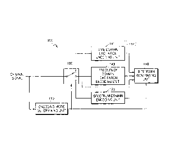
occur, but
also decoded sound quality is deteriorated. Furthermore, since there is no
technique for
correcting a primarily determined encoding mode, i.e. class, if an error
occurs during
determination of an encoding mode, the quality of a reconstructed audio signal
is
deteriorated.
[Disclosure]
[Technical Problem]
[4] Aspects of one or more exemplary embodiments provide a method and an
apparatus for determining an encoding mode for improving the quality of a
reconstructed audio signal, by determining an encoding mode appropriate to
characteristics of an audio signal, a method and an apparatus for encoding an
audio
signal, and a method and an apparatus for decoding an audio signal.
[5] Aspects of one or more exemplary embodiments provide a method and an
apparatus for determining an encoding mode appropriate to characteristics of
an
1
CA 2891413 2018-02-20
CA 02891413 2015-05-13
audio signal and reducing delays due to frequent encoding mode switching, a
method and an apparatus for encoding an audio signal, and a method and an
apparatus for decoding an audio signal.
[Technical Solution]
[6] According to an aspect of one or more exemplary embodiments, there is a
method of determining an encoding mode, the method including determining one
from among a plurality of encoding modes including a first encoding mode and a
second encoding mode as an initial encoding mode in correspondence to
characteristics of an audio signal, and if there is an error in the
determination of the
initial encoding mode, generating a corrected encoding mode by correcting the
initial
encoding mode to a third encoding mode.
[7] According to an aspect of one or more exemplary embodiments, there is a
method of encoding an audio signal, the method including determining one from
among a plurality of encoding modes including a first encoding mode and a
second
encoding mode as an initial encoding mode in correspondence to characteristics
of
an audio signal, if there is an error in the determination of the initial
encoding mode,
generating a corrected encoding mode by correcting the initial encoding mode
to a
third encoding mode, and performing different encoding processes on the audio
signal based on either the initial encoding mode or the corrected encoding
mode.
[8] According to an aspect of one or more exemplary embodiments, there is a
method of decoding an audio signal, the method including parsing a bitstream
comprising one of an initial encoding mode obtained by determining one from
among
a plurality of encoding modes including a first encoding mode and a second
encoding mode in correspondence to characteristics of an audio signal and a
third
encoding mode corrected from the initial encoding mode if there is an error in
the
determination of the initial encoding mode, and performing different decoding
processes on the bitstream based on either the initial encoding mode or the
third
encoding mode.
[Advantageous Effects]
[9] According to exemplary embodiments, by determining the final encoding
mode of a current frame based on correction of the initial encoding mode and
encoding modes of frames corresponding to a hangover length, an encoding mode
2
CA 02891413 2015-05-13
adaptive to characteristics of an audio signal may be selected while
preventing
frequent encoding mode switching between frames.
[Description of Drawings]
[10] FIG. 1 is a block diagram illustrating a configuration of an audio
encoding
apparatus according to an exemplary embodiment;
[11] FIG. 2 is a block diagram illustrating a configuration of an audio
encoding
apparatus according to another exemplary embodiment;
[12] FIG. 3 is a block diagram illustrating a configuration of an encoding
mode
determining unit according to an exemplary embodiment;
[13] FIG. 4 is a block diagram illustrating a configuration of an initial
encoding
mode determining unit according to an exemplary embodiment;
[14] FIG. 5 is a block diagram illustrating a configuration of a feature
parameter
extracting unit according to an exemplary embodiment;
[15] FIG. 6 is a diagram illustrating an adaptive switching method between a
linear
prediction domain encoding and a spectrum domain according to an exemplary
embodiment;
[16] FIG. 7 is a diagram illustrating an operation of an encoding mode
correcting
unit according to an exemplary embodiment;
[17] FIG. 8 is a block diagram illustrating a configuration of an audio
decoding
apparatus according to an exemplary embodiment; and
[18] FIG. 9 is a block diagram illustrating a configuration of an audio
decoding
apparatus according to another exemplary embodiment.
[Mode for Invention]
[19] Reference will now be made in detail to embodiments, examples of which
are
illustrated in the accompanying drawings, wherein like reference numerals
refer to
like elements throughout. In this regard, the present embodiments may have
different forms and should not be construed as being limited to the
descriptions set
forth herein. Accordingly, the embodiments are merely described below, by
referring to the figures, to explain aspects of the present description.
[20] Terms such as "connected" and "linked" may be used to indicate a directly
connected or linked state, but it shall be understood that another component
may be
interposed therebetween.
3
CA 02891413 2015-05-13
[21] Terms such as "first" and "s,econd" may be used to describe various
components, but the components shall not be limited to the terms. The terms
may
be used only to distinguish one component from another component.
[22] The units described in exemplary embodiments are independently
illustrated
to indicate different characteristic functions, and it does not mean that each
unit is
formed of one separate hardware or software component. Each unit is
illustrated
for the convenience of explanation, and a plurality of units may form one
unit, and
one unit may be divided into a plurality of units.
[23] FIG. 1 is a block diagram illustrating a configuration of an audio
encoding
apparatus 100 according to an exemplary embodiment.
[24] The audio encoding apparatus 100 shown in FIG. 1 may include an encoding
mode determining unit 110, a switching unit 120, a spectrum domain encoding
unit
130, a linear prediction domain encoding unit 140, and a bitstream generating
unit
150. The linear prediction domain encoding unit 140 may include a time domain
excitation encoding unit 141 and a frequency domain excitation encoding unit
143,
where the linear prediction domain encoding unit 140 may be embodied as at
least
one of the two excitation encoding units 141 and 143. Unless it is necessary
to be
embodied as a separate hardware, the above-stated components may be integrated
into at least one module and may be implemented as at least one processor (not
shown). Here, the term of an audio signal may refer to a music signal, a
speech
signal, or a mixed signal thereof.
[25] Referring to FIG. 1, the encoding mode determining unit 110 may
analyze
characteristics of an audio signal to determine the class of the audio signal,
and
determine an encoding mode in correspondence to a result of the
classification.
The determining of the encoding mode may be performed in units of
superfrannes,
frames, or bands. Alternatively, the determining of the encoding mode may be
performed in units of a plurality of superframe groups, a plurality of frame
groups, or
a plurality of band groups. Here, examples of the encoding modes may include a
spectrum domain and a time domain or a linear prediction domain, but are not
limited
thereto. If performance and processing speed of a processor are sufficient and
delays due to encoding mode switching may be resolved, encoding modes may be
subdivided, and encoding schemes may also be subdivided in correspondence to
the encoding mode. According to an exemplary embodiment, the encoding mode
determining unit 110 may determine an initial encoding mode of an audio signal
as
4
CA 02891413 2015-05-13
one of a spectrum domain encoding mode and a time domain encoding mode.
According to another exemplary embodiment, the encoding mode determining unit
110 may determine an initial encoding mode of an audio signal as one of a
spectrum
domain encoding mode, a time domain excitation encoding mode and a frequency
domain excitation encoding mode. If the spectrum domain encoding mode is
determined as the initial encoding mode, the encoding mode determining unit
110
may correct the initial encoding mode to one of the spectrum domain encoding
mode
and the frequency domain excitation encoding mode. If the time domain encoding
mode, that is, the time domain excitation encoding mode is determined as the
initial
encoding mode, the encoding mode determining unit 110 may correct the initial
encoding mode to one of the time domain excitation encoding mode and the
frequency domain excitation encoding mode. If the
time domain excitation
encoding mode is determined as the initial encoding mode, the determination of
the
final encoding mode may be selectively performed. In other words, the initial
encoding mode, that is, the time domain excitation encoding mode may be
maintained. The encoding mode determining unit 110 may determine encoding
modes of a plurality of frames corresponding to a hangover length, and may
determine the final encoding mode for a current frame. According to an
exemplary
embodiment, if the initial encoding mode or a corrected encoding mode of a
current
frame is identical to encoding modes of a plurality of previous frames, e.g.,
7
previous frames, the corresponding initial encoding mode or corrected encoding
mode may be determined as the final encoding mode of the current frame.
Meanwhile, if the initial encoding mode or a corrected encoding mode of a
current
frame is not identical to encoding modes of a plurality of previous frames,
e.g., 7
previous frames, the encoding mode determining unit 110 may determine the
encoding mode of the frame just before the current frame as the final encoding
mode
of the current frame.
[26] As described above, by determining the final encoding mode of a current
frame based on correction of the initial encoding mode and encoding modes of
frames corresponding to a hangover length, an encoding mode adaptive to
characteristics of an audio signal may be selected while preventing frequent
encoding mode switching between frames.
[27] Generally, the time domain encoding, that is, the time domain excitation
encoding may be efficient for a speech signal, the spectrum domain encoding
may
5
CA 02891413 2015-05-13
be efficient for a music signal, and the frequency domain excitation encoding
may be
efficient for a vocal and/or harmonic signal.
[28] In correspondence to an encoding mode determined by the encoding mode
determining unit 110, the switching unit 120 may provide an audio signal to
either the
spectrum domain encoding unit 130 or the linear prediction domain encoding
unit
140. If the linear prediction domain encoding unit 140 is embodied as the time
domain excitation encoding unit 141, the switching unit 120 may include total
two
branches. If the linear prediction domain encoding unit 140 is embodied as the
time
domain excitation encoding unit 141 and the frequency domain excitation
encoding
unit 143, the switching unit 120 may have total 3 branches.
[29] The spectrum domain encoding unit 130 may encode an audio signal in
the
spectrum domain. The spectrum domain may refer to the frequency domain or a
transform domain. Examples of coding methods applicable to the spectrum domain
encoding unit 130 may include an advance audio coding (AAC), or a combination
of
a modified discrete cosine transform (MDCT) and a factorial pulse coding
(FPC), but
are not limited thereto. In detail, other quantizing techniques and entropy
coding
techniques may be used instead of the FPC. It may be efficient to encode a
music
signal in the spectrum domain encoding unit 130.
[30] The linear prediction domain encoding unit 140 may encode an audio signal
in
a linear prediction domain. The linear prediction domain may refer to an
excitation
domain or a time domain. The linear prediction domain encoding unit 140 may be
embodied as the time domain exc;:tation encoding unit 141 or may be embodied
to
include the time domain excitation encoding unit 141 and the frequency domain
excitation encoding unit 143. Examples of coding methods applicable to the
time
domain excitation encoding unit 141 may include code excited linear prediction
(CELP) or an algebraic CELP (ACELP), but are not limited thereto. Examples of
coding methods applicable to the frequency domain excitation encoding unit 143
may include general signal coding (GSC) or transform coded excitation (TCX),
are
not limited thereto. It may be efficient to encode a speech signal in the time
domain
excitation encoding unit 141, whereas it may be efficient to encode a vocal
and/or
harmonic signal in the frequency domain excitation encoding unit 143.
[31] The bitstream generating unit 150 may generate a bitstream to include the
encoding mode provided by the encoding mode determining unit 110, a result of
6
CA 02891413 2015-05-13
encoding provided by the spectrum domain encoding unit 130, and a result of
encoding provided by the linear prediction domain encoding unit 140.
[32] FIG. 2 is a block diagram illustrating a configuration of an audio
encoding
apparatus 200 according to another exemplary embodiment.
[33] The audio encoding apparatus 200 shown in FIG. 2 may include a common
pre-processing module 205, an encoding mode determining unit 210, a switching
unit 220, a spectrum domain encoding unit 230, a linear prediction domain
encoding unit 240, and a bitstream generating unit 250. Here, the linear
prediction
domain encoding unit 240 may include a time domain excitation encoding unit
241
and a frequency domain excitation encoding unit 243, and the linear prediction
domain encoding unit 240 may be embodied as either the time domain excitation
encoding unit 241 or the frequency domain excitation encoding unit 243.
Compared
to the audio encoding apparatus 100 shown in FIG.1, the audio encoding
apparatus
200 may further include the common pre-processing module 205, and thus
descriptions of components identical to those of the audio encoding apparatus
100
will be omitted.
[34] Referring to FIG. 2, the common pre-processing module 205 may perform
joint stereo processing, surround processing, and/or bandwidth extension
processing.
The joint stereo processing, the surround processing, and the bandwidth
extension
processing may be identical to those employed by a specific standard, e.g.,
the
MPEG standard, but are not limited thereto. Output
of the common pre-processing
module 205 may be in a mono channel, a stereo channel, or multi channels.
According to the number of channels of an signal output by the common
pre-processing module 205, the switching unit 220 may include at least one
switch.
For example, if the common pre-processing module 205 outputs a signal of two
or
more channels, that is, a stereo channel or a multi-channel, switches
corresponding
to the respective channels may be arranged. For example, the first channel of
a
stereo signal may be a speech channel, and the second channel of the stereo
signal
may be a music channel. In this case, an audio signal may be simultaneously
provided to the two switches. Additional information generated by the common
pre-processing module 205 may be provided to the bitstream generating unit 250
and included in a bitstream. The additional information may be necessary for
performing the joint stereo processing, the surround processing, and/or the
bandwidth extension processing in a decoding end and may include spatial
7
CA 02891413 2015-05-13
parameters, envelope information, energy information, etc. However, there may
be
various additional information based on processing techniques applied thereto.
[35] According to an exemplary embodiment, at the common pre-processing
module 205, the bandwidth extension processing may be differently performed
based on encoding domains. The audio signal in a core band may be processed by
using the time domain excitation encoding mode or the frequency domain
excitation
encoding mode, whereas an audio signal in a bandwidth extended band may be
processed in the time domain. The bandwidth extension processing in the time
domain may include a plurality of modes including a voiced mode or an unvoiced
mode. Alternatively, an audio signal in the core band may be processed by
using
the spectrum domain encoding mode, whereas an audio signal in the bandwidth
extended band may be processed in the frequency domain. The bandwidth
extension processing in the frequency domain may include a plurality of modes
including a transient mode, a normal mode, or a harmonic mode. To perform
.. bandwidth extension processing in different domains, an encoding mode
determined
by the encoding mode determining unit 110 may be provided to the common
pre-processing module 205 as a signaling information. According to an
exemplary
embodiment, the last portion of the core band and the beginning portion of the
bandwidth extended band may overlap each other to some extent. Location and
size of the overlapped portions may be set in advance.
[36] FIG. 3 is a block diagram illustrating a configuration of an encoding
mode
determining unit 300 according to an exemplary embodiment.
[37] The encoding mode determining unit 300 shown in FIG. 3 may include an
initial encoding mode determining'unit 310 and an encoding mode correcting
unit
330.
[38] Referring to FIG. 3, the initial encoding mode determining unit 310
may
determine whether an audio signal is a music signal or a speech signal by
using
feature parameters extracted from the audio signal. If the
audio signal is
determined as a speech signal, linear prediction domain encoding may be
suitable.
Meanwhile, if the audio signal is determined as a music signal, spectrum
domain
encoding may be suitable. The initial encoding mode determining unit 310 may
determine the class of the audio signal indicating whether spectrum domain
encoding, time domain excitation encoding, or frequency domain excitation
encoding
is suitable for the audio signal by using feature parameters extracted from
the audio
8
CA 02891413 2015-05-13
signal. A corresponding encoding mode may be determined based on the class of
the audio signal. If a switching unit (120 of FIG. 1) has two branches, an
encoding
mode may be expressed in 1-bit. If the switching unit (120 of FIG. 1) has
three
branches, an encoding mode may be expressed in 2-bits. The initial encoding
mode determining unit 310 may determine whether an audio signal is a music
signal
or a speech signal by using any cif various techniques known in the art.
Examples
thereof may include FD/LPD classification or ACELP/TCX classification
disclosed in
an encoder part of the USAC standard and ACELPTTCX classification used in the
AMR standards, but are not limited thereto. In other words, the initial
encoding
mode may be determined by using any of various methods other than the method
according to embodiments described herein.
[39] The encoding mode correcting unit 330 may determine a corrected
encoding
mode by correcting the initial encoding mode determined by the initial
encoding
mode determining unit 310 by using correction parameters. According to an
exemplary embodiment, if the spectrum domain encoding mode is determined as
the
initial encoding mode, the initial encoding mode may be corrected to the
frequency
domain excitation encoding mode based on correction parameters. If the time
domain encoding mode is determined as the initial encoding mode, the initial
encoding mode may be corrected to the frequency domain excitation encoding
mode
based on correction parameters. In other words, it is determined whether there
is
an error in determination of the initial encoding mode by using correction
parameters.
If it is determined that there is no error in the determination of the initial
encoding
mode, the initial encoding mode may be maintained. On the contrary, if it is
determined that there is an error in the determination of the initial encoding
mode,
the initial encoding mode may be corrected. The correction of the initial
encoding
mode may be obtained from the spectrum domain encoding mode to the frequency
domain excitation encoding mode and from the time domain excitation encoding
mode to frequency domain excitation encoding mode.
[40] Meanwhile, the initial encoding mode or the corrected encoding mode may
be
a temporary encoding mode for a current frame, where the temporary encoding
mode for the current frame may be compared to encoding modes for previous
frames within a preset hangover length and the final encoding mode for the
current
frame may be determined.
9
CA 02891413 2015-05-13
[41] FIG. 4 is a block diagram illustrating a configuration of an initial
encoding
mode determining unit 400 according to an exemplary embodiment.
[42] The initial encoding mode determining unit 400 shown in FIG. 4 may
include a
feature parameter extracting unit 410 and a determining unit 430.
[43] Referring to FIG. 4, the feature parameter extracting unit 410 may
extract
feature parameters necessary for determining an encoding mode from an audio
signal. Examples of the extracted feature parameters include at least one or
two
from among a pitch parameter, a voicing parameter, a correlation parameter,
and a
linear prediction error, but are not limited thereto. Detailed descriptions of
individual
parameters will be given below.
[44] First, a first feature parameter F, relates to a pitch parameter, where a
behavior of pitch may be determined by using N pitch values detected in a
current
frame and at least one previous frame. To prevent an effect from a random
deviation or a wrong pitch value, M pitch values significantly different from
the
average of the N pitch values may be removed. Here, N and M may be values
obtained via experiments or simulations in advance. Furthermore, N may be set
in
advance, and a difference between a pitch value to be removed and the average
of
the N pitch values may be determined via experiments or simulations in
advance.
The first feature parameter F, may be expressed as shown in Equation 1 below
by
.. using the average rnp, and the variance crp, with respect to (N-M) pitch
values.
[45] [Equation 11
F1 ¨ ______________
rn r
[46] A second feature parameter F2 also relates to a pitch parameter and may
indicate reliability of a pitch value detected in a current frame. = The
second feature
parameter F2 may be expressed as shown in Equation 2 bellow by using variances
GsFi and CYSF2 of pitch values respectively detected in two sub-frames SF, and
SF2 of
a current frame.
[47] [Equation 2]
cov(S.F1, SF2)
F2 -
181,43ST,
[48] Here, cov(SF1,SF2) denotes the covariance between the sub-frames SF, and
SF2. In other words, the second feature parameter F2 indicates correlation
between
CA 02891413 2015-05-13
two sub-frames as a pitch distance. According to an exemplary embodiment, a
current frame may include two or more sub-frames, and Equation 2 may be
modified
based on the number of sub-frames.
[49] A third feature parameter F3 may be expressed as shown in Equation 3
below
based on a voicing parameter Voicing and a correlation parameter Corr.
[50] [Equation 3]
I C Voicing 7 CO/7-C2
[51] Here, the voicing parameter Voicing relates to vocal features of sound
and
may be obtained any of various methods known in the art, whereas the
correlation
parameter Corr may be obtained by summing correlations between frames for each
band.
[52] A fourth feature parameter F4 relates to a linear prediction error ELpc
and may
be expressed as shown in Equation 4 below.
[53] [Equation 4]
(E/pci -WEirc))2
= F4 ¨
[54] Here, M(Ei_pc) denotes the average of N linear prediction errors.
[55] The determining unit 430 may determine the class of an audio signal by
using
at least one feature parameter provided by the feature parameter extracting
unit 410
and may determine the initial encoding mode based on the determined class. The
determining unit 430 may employ soft decision mechanism, where at least one
mixture may be formed per feature parameter. According to an exemplary
embodiment, the class of an audio signal may be determined by using the
Gaussian
mixture model (GMM) based on mixture probabilities. A probability f(x)
regarding
one mixture may be calculated according to Equation 5 below.
[56] [Equation 51
1 -0.5 (x-rn)TC (x-rn)
f(x)
V (211)N det(C 1)
¨ (lc 1,... ,x
In ¨ (Cx1C,...,CxNC)
[57] Here, x denotes an input vector of a feature parameter, m
denotes a mixture,
11
CA 02891413 2015-05-13
and c denotes a covariance matrix.
[58] The determining unit 430 may calculate a music probability Pm and a
speech
probability Ps by using Equation 6 below.
[59] [Equation 6]
Pm Q .P Pa Q .P
/MI triS
[60] Here, the music probability Pm may be calculated by adding probabilities
Pi of
M mixtures related to feature parameters superior for music determination,
whereas
the speech probability Ps may be Calculated by adding probabilities Pi of S
mixtures
related to feature parameters superior for speech determination.
[61] Meanwhile, for improved precision, the music probability Pm and the
speech
probability Ps may be calculated according to Equation 7 below.
[62] [Equation 7]
P m = Q 2#(1-P7r) Q P i(P7)
it.AI ibS
P a Q P 71)ein) Q P i(Peirr)
lbS i311
Orr
[63] Here, Pi denotes error probability of each mixture. The error probability
may be obtained by classifying training data incuding clean speech signals and
clean
music signals using each of mixtures and counting the number of wrong
classifications.
[64] Next, the probability Pm that all frames include music signals only
and the
speech probability Ps that all frames include speech signals only with
respect,to a
plurality of frames as many as a constant hangover length may be calculated
according to Equation 8 below. The hangover length may be set to 8, but is not
limited thereto. Eight frames may include a current frame and 7 previous
frames.
[65] [Equation 81
12
CA 02891413 2016-10-27
-7
P(õii)
Ar I .0
P .7 .7
t- (1 m(i) pt,i)
-7
0 Pls:"
$ 1=0
P
0 p( 4. 0 ptih
m
i-o
s
"
[66] Next, a plurality of conditions sets {D1} and {.1--ry 1) may be
calculated by using
the music probability Pm or the speech probability Ps obtained using Equation
5 or
Equation 6. Detailed descriptions thereof will be given below with reference
to FIG.
6. Here, it may be set such that each condition has a value 1 for music and
has a
value 0 for speech.
[67] Referring to FIG. 6, in an operation 610 and an operation 620, a sum of
music
conditions M and a sum of voice conditions S may be obtained from the
plurality of
,s
m
condition sets {D1} and {III} that are calculated by using the music
probability Pm
and the speech probability Ps. In other words, the sum of music conditions M
and
the sum of speech conditions S may be expressed as shown in Equation 9 below.
[68] [Equation 9]
M
S Q
[69] In an operation 630, the sum of music conditions M is compared to a
designated threshold value Tm. If the sum of music conditions M is greater
than the
threshold value Tm, an encoding mode of a current frame is switched (operation
650) to a music mode, that is, the spectrum domain encoding mode. If the sum
of
music conditions M is smaller than or equal to the threshold value Tm, the
encoding
mode of the current frame is not changed (operation 670).
[70] In an operation 640, the sum of speech conditions S is compared to a
designated threshold value Ts. If the sum of speech conditions S is greater
than the
threshold value Ts, an encoding mode of a current frame is switched (operation
660) to a speech mode, that is, the linear prediction domain encoding mode. If
the
sum of speech conditions S is smaller than or equal to the threshold value Ts,
the
encoding mode of the current frame is not changed (operation 670).
13
CA 02891413 2016-10-27
[71] The threshold value Tm and the threshold value Ts may be set to values
obtained via experiments or simulations in advance.
[72] FIG. 5 is a block diagram illustrating a configuration of a feature
parameter
extracting unit 500 according to an exemplary embodiment.
[73] An initial encoding mode determining unit 500 shown in FIG. 5 may include
a
transform unit 510, a spectral parameter extracting unit 520, a temporal
parameter
extracting unit 530, and a determining unit (430 of FIG. 4).
[74] In FIG. 5, the transform unit 510 may transform an original audio signal
from
the time domain to the frequency domain. Here, the transform unit 510 may
apply
any of various transform techniques for representing an audio signal from a
time
domain to a spectrum domain. Examples of the techniques may include fast
Fourier
transform (FFT), discrete cosine transform (DCT), or modified discrete cosine
transform (MDCT), but are not limited thereto.
[75] The spectral parameter extracting unit 520 may extract at least one
spectral
parameter from a frequency domain audio signal provided by the transform unit
510.
Spectral parameters may be categorized into short-term feature parameters and
long-term feature parameters. The short-term feature parameters may be
obtained
from a current frame, whereas the long-term feature parameters may be obtained
from a plurality of frames including the current frame and at least one
previous
frame.
[76] The temporal parameter extracting unit 530 may extract at least one
temporal
parameter from a time domain audio signal. Temporal parameters may also be
categorized into short-term feature parameters and long-term feature
parameters.
The short-term feature parameters may be obtained from a current frame,
whereas
the long-term feature parameters may be obtained from a plurality of frames
including the current frame and at least one previous frame.
[77] A determining unit (430 of FIG. 4) may determine the class of an audio
signal
by using spectral parameters provided by the spectral parameter extracting
unit 520
and temporal parameters provided by the temporal parameter extracting unit 530
and may determine the initial encoding mode based on the determined class. The
determining unit (430 of FIG. 4) may employ soft decision mechanism.
14
CA 02891413 2015-05-13
[78] FIG. 7 is a diagram illustrating an operation of an encoding mode
correcting
unit 310 according to an exemplary embodiment.
[79] Referring to FIG. 7, in an operation 700, an initial encoding mode
determined
by the initial encoding mode determining unit 310 is received and it may be
determined whether the encoding mode is the time domain mode, that is, the
time
domain excitation mode or the spectrum domain mode.
[80] In an operation 701, if it is determined in the operation 700 that the
initial
encoding mode is the spectrum domain mode (state-rs == 1), an index state-r-
rss
indicating whether the frequency domain excitation encoding is more
appropriate
may be checked. The index state-rms indicating whether the frequency domain
excitation encoding (e.g., GSC) is more appropriate may be obtained by using
tonalities of different frequency bands. Detailed descriptions thereof will be
given
below.
[81] Tonality of a low band signal may be obtained as a ratio between a sum
of a
plurality of spectrum coefficients having small values including the smallest
value
and the spectrum coefficient having the largest value with respect to a given
band.
If given bands are 0-1 kHz, 1-2 kHz, and 2-4 kHz, tonalities tot t12, and t24
of the
respective bands and tonality tL of a low band signal, that is, the core band
may be
expressed as shown in Equation 10 below.
[82] [Equation 10]
max(x)
foi ¨ 0.2 log10( _______ µ. IVH [ 0, ....,1kHZI
Q SO/1(X
jr0
ratIX(X,)
t I2 0.2 k)g. 1 ) UHf i...,2k[IzJ
Q sori(rj)
jO
inax(x,)
t,4 = 0.2 log 10( m_i ijH[2,....,4A-Hz1
Qsort(xj)
j-0
ti max(tol 412424)
[83] Meanwhile, the linear prediction error err may be obtained by using a
linear
prediction coding (LPC) filter and may be used to remove strong tonal
components.
In other words, the spectrum domain encoding mode may be more efficient with
CA 02891413 2015-05-13
respect to strong tonal components than the frequency domain excitation
encoding
mode.
[84] A front condition condfront for switching to the frequency domain
excitation
encoding mode by using the tonalities and the linear prediction error obtained
as
described above may be expressed as shown in Equation 11 below.
[85] [Equation 11]
condfront= 112 > 1-12fiont and t24 > i24fron, and tL> t and err >
err
[86] Here, .12front, t24front, tLfront, and errfront are threshold values
and may have values
obtained via experiments or simulations in advance.
[87] Meanwhile, a back condition condbaok for finishing the frequency domain
excitation encoding mode by using the tonalities and the linear prediction
error
obtained as described above may be expressed as shown in Equation 12 below.
[88] [Equation 12]
can dbewk = t12 12back and t24< 124back and t1< lback
[89] Here, tl2back, t24back, kback are threshold values and may have values
obtained
via experiments or simulations in advance.
[90] In other words, it may be determined whether the index stateuss
indicating
whether the frequency domain excitation encoding (e.g., GSC) is more
appropriate
than the spectrum domain encoding is 1 by determining whether the front
condition
shown in Equation 11 is satisfied or the back condition shown in Equation 12
is not
satisfied. Here, the determination of the back condition shown in Equation 12
may
be optional.
[91] In an operation 702, if the index stateuss is 1, the frequency domain
excitation encoding mode may be determined as the final encoding mode. In this
case, the spectrum domain encoding mode, which is the initial encoding mode,
is
corrected to the frequency domain excitation encoding mode, which is the final
encoding mode.
[92] In an operation 705, if it is determined in the operation 701 that the
index
state-n-ss is 0, an index states for determining whether an audio signal
includes a
strong speech characteristic may be checked. If there is an error in the
determination of the spectrum domain encoding mode, the frequency domain
excitation encoding mode may be more efficient than the spectrum domain
encoding
16
CA 02891413 2015-05-13
mode. The index statess for determining whether an audio signal includes a
strong
speech characteristic may be obtained by using a difference vc between a
voicing
parameter and a correlation parameter.
[93] A front condition condfront for switching to a strong speech mode by
using the
difference vc between a voicing parameter and a correlation parameter may be
expressed as shown in Equation 13 below.
[94] [Equation 13]
cond = vc > vcfm7,1
[95] Here, vcfront is a threshold value and may have a value obtained via
.. experiments or simulations in advance.
[96] Meanwhile, a back condition condbaok for finishing the strong speech mode
by
using the difference vc between a voicing parameter and a correlation
parameter
may be expressed as shown in Equation 14 below.
[97] [Equation 14]
condback =
1')C < VC back
[98] Here, vcbaok is a threshold value and may have a value obtained via
experiments or simulations in advance.
[99] In other words, in an operation 705, it may be determined whether the
index
statess indicating whether the frequency domain excitation encoding (e.g. GSC)
is
more appropriate than the spectrum domain encoding is 1 by determining whether
the front condition shown in Equation 13 is satisfied or the back condition
shown in
Equation 14 is not satisfied. Here, the determination of the back condition
shown in
Equation 14 may be optional.
[100] In an operation 706, if it is determined in the operation 705 that the
index
statess is 0, i.e. the audio signal does not include a strong speech
characteristic, the
spectrum domain encoding mode may be determined as the final encoding mode.
In this case, the spectrum domain encoding mode, which is the initial encoding
mode,
is maintained as the final encoding mode.
[101] In an operation 707, if it is determined in the operation 705 that the
index
statess is 1, i.e. the audio signal includes a strong speech characteristic,
the
frequency domain excitation encoding mode may be determined as the final
encoding mode. In this case, the spectrum domain encoding mode, which is the
initial encoding mode, is corrected to the frequency domain excitation
encoding
mode, which is the final encoding mode.
17
CA 02891413 2015-05-13
[102] By performing the operations 700, 701, and 705, an error in the
determination
of the spectrum domain encoding mode as the initial encoding mode may be
corrected. In detail, the spectrum domain encoding mode, which is the initial
encoding mode, may be maintained or switched to the frequency domain
excitation
encoding mode as the final encoding mode.
[103] Meanwhile, if it is determined in the operation 700 that the initial
encoding
mode is the linear prediction domain encoding mode (stateTs == 0), an index
statesm
for determining whether an audio signal includes a strong music characteristic
may
be checked. If there is an error in the determination of the linear prediction
domain
encoding mode, that is, the time domain excitation encoding mode, the
frequency
domain excitation encoding mode may be more efficient than the time domain
excitation encoding mode. The statesm for determining whether an audio signal
includes a strong music characteristic may be obtained by using a value 1-vc
obtained by subtracting the difference vc between a voicing parameter and a
correlation parameter from 1.
[104] A front condition condfront for switching to a strong music mode by
using the
value 1-vc obtained by subtracting the difference vc between a voicing
parameter
and a correlation parameter from 1 may be expressed as shown in Equation 15
below.
[105] [Equation 15]
conclt = 1 -vc > win f7Qõ,
[106] Here, vcmfront is a threshold value and may have a value obtained via
experiments or simulations in advance.
[107] Meanwhile, a back condition condback for finishing the strong music mode
by
using the value 1-vc obtained by subtracting the difference vc between a
voicing
parameter and a correlation parameter from 1 may be expressed as shown in
Equation 16 below.
[108] [Equation 16]
conciback = 1 - vie < vcmback
[109] Here, vcmback is a threshold value and may have a value obtained via
experiments or simulations in advance.
18
CA 02891413 2015-05-13
[110] In other words, in an operation 709, it may be determined whether the
index
statesm indicating whether the frequency domain excitation encoding (e.g. GSC)
is
more appropriate than the time domain excitation encoding is 1 by determining
whether the front condition shown in Equation 15 is satisfied or the back
condition
shown in Equation 16 is not satisfied. Here, the determination of the back
condition
shown in Equation 16 may be optional.
[111] In an operation 710, if it is determined in the operation 709 that the
index
statesm is 0 i.e. the audio signal does not include a strong music
characteristic, the
time domain excitation encoding mode may be determined as the final encoding
mode. In this case, the linear prediction domain encoding mode, which is the
initial
encoding mode, is switched to the time domain excitation encoding mode as the
final
encoding mode. According to an exemplary embodiment, it may be considered that
the initial encoding mode is maintained without changes, if the linear
prediction
domain encoding mode corresponds to the time domain excitation encoding mode.
.. [112] In an operation 707, if it is determined in the operation 709 that
the index
statesm is 1 i.e. the audio signal includes a strong music characteristic, the
frequency
domain excitation encoding mode may be determined as the final encoding mode.
In this case, the linear prediction domain encoding mode, which is the initial
encoding mode, is corrected to the frequency domain excitation encoding mode,
which is the final encoding mode.
[113] By performing the operations 700 and 709, an error in the determination
of the
initial encoding mode may be corrected. In detail, the linear prediction
domain
encoding mode (e.g., the time domain excitation encoding mode), which is the
initial
encoding mode, may be maintained or switched to the frequency domain
excitation
.. encoding mode as the final encoding mode.
[114] According to an exemplary embodiment, the operation 709 for determining
whether the audio signal includes a strong music characteristic for correcting
an
error in the determination of the linear prediction domain encoding mode may
be
optional.
[115] According to another exemplary embodiment, a sequence of performing the
operation 705 for determining whether the audio signal includes a strong
speech
characteristic and the operation 701 for determining whether the frequency
domain
excitation encoding mode is appropriate may be reversed. In other words, after
the
operation 700, the operation 705 may be performed first, and then the
operation 701
19
CA 02891413 2015-05-13
may be performed. In this case, parameters used for the determinations may be
changed as occasions demand.
[116] FIG. 8 is a block diagram illustrating a configuration of an audio
decoding
apparatus 800 according to an exemplary embodiment.
[117] The audio decoding apparatus 800 shown in FIG. 8 may include a bitstream
parsing unit 810, a spectrum domain decoding unit 820, a linear prediction
domain
decoding unit 830, and a switching unit 840. The linear prediction domain
decoding
unit 830 may include a time domain excitation decoding unit 831 and a
frequency
domain excitation decoding unit 833, where the linear prediction domain
decoding
unit 830 may be embodied as at least one of the time domain excitation
decoding
unit 831 and the frequency domain excitation decoding unit 833. Unless it is
necessary to be embodied as a separate hardware, the above-stated components
may be integrated into at least one module and may be implemented as at least
one
processor (not shown).
[118] Referring to FIG. 8, the bitstream parsing unit 810 may parse a received
bitstream and separate information on an encoding mode and encoded data. The
encoding mode may correspond to either an initial encoding mode obtained by
determining one from among a plurality of encoding modes including a first
encoding
mode and a second encoding mode in correspondence to characteristics of an
audio
signal or a third encoding mode corrected from the initial encoding mode if
there is
an error in the determination of the initial encoding mode.
[119] The spectrum domain decoding unit 820 may decode data encoded in the
spectrum domain from the separated encoded data.
[120] The linear prediction domain decoding unit 830 may decode data encoded
in
the linear prediction domain from the separated encoded data. If the linear
prediction domain decoding unit 830 includes the time domain excitation
decoding
unit 831 and the frequency domain excitation decoding unit 833, the linear
prediction
domain decoding unit 830 may perform time domain excitation decoding or
frequency domain exciding decoding with respect to the separated encoded data.
[121] The switching unit 840 may switch either a signal reconstructed by the
spectrum domain decoding unit 820 or a signal reconstructed by the linear
prediction
domain decoding unit 830 and may provide the switched signal as a final
reconstructed signal.
CA 02891413 2015-05-13
[122] FIG. 9 is a block diagram illustrating a configuration of an audio
decoding
apparatus 900 according to another exemplary embodiment.
[123] The audio decoding apparatus 900 may include a bitstream parsing unit
910,
a spectrum domain decoding unit 920, a linear prediction domain decoding unit
930,
a switching unit 940, and a common post-processing module 950. The linear
prediction domain decoding unit 930 may include a time domain excitation
decoding
unit 931 and a frequency domain excitation decoding unit 933, where the linear
prediction domain decoding unit 930 may be embodied as at least one of time
domain excitation decoding unit 931 and the frequency domain excitation
decoding
unit 933. Unless it is necessary to be embodied as a separate hardware, the
above-stated components may be integrated into at least one module and may be
implemented as at least one processor (not shown). Compared to the audio
decoding apparatus 800 shown in FIG. 8, the audio decoding apparatus 900 may
further include the common post-processing module 950, and thus descriptions
of
.. components identical to those of the audio decoding apparatus 800 will be
omitted.
[124] Referring to FIG. 9, the common post-processing module 950 may perform
joint stereo processing, surround processing, and/or bandwidth extension
processing,
in correspondence to a common pre-processing module (205 of FIG. 2).
[125] The methods according to the exemplary embodiments can be written as
computer-executable programs and can be implemented in general-use digital
computers that execute the programs by using a non-transitory computer-
readable
recording medium. In addition, data structures, program instructions, or data
files,
which can be used in the embodiments, can be recorded on a non-transitory
computer-readable recording medium in various ways. The non-transitory
computer-readable recording medium is any data storage device that can store
data
which can be thereafter read by a computer system. Examples of the non-
transitory
computer-readable recording medium include magnetic storage media, such as
hard
disks, floppy disks, and magnetic tapes, optical recording media, such as CD-
ROMs
and DVDs, magneto-optical media, such as optical disks, and hardware devices,
such as ROM, RAM, and flash memory, specially configured to store and execute
program instructions. In addition, the non-transitory computer-readable
recording
medium may be a transmission medium for transmitting signal designating
program
instructions, data structures, or the like. Examples of the program
instructions may
21
CA 02891413 2015-05-13
include not only mechanical language codes created by a compiler but also
high-level language codes executable by a computer using an interpreter or the
like.
[126] While exemplary embodiments have been particularly shown and described
above, it will be understood by those of ordinary skill in the art that
various changes
in form and details may be made therein without departing from the spirit and
scope
of the inventive concept as defined by the appended claims. The exemplary
embodiments should be considered in descriptive sense only and not for
purposes of
limitation. Therefore, the scope of the inventive concept is defined not by
the detailed
description of the exemplary embodiments but by the appended claims, and all
differences within the scope will be construed as being included in the
present
inventive concept.
22