Note: Descriptions are shown in the official language in which they were submitted.
CA 02892272 2015-05-22
WO 2014/078910 PCT/AU2013/001359
FOULING RESISTANT FLOW MAINIFOLD
FIELD OF THE INVENTION
[0001] The present invention relates generally to manifolds for sensor
equipment used
in monitoring the flow of liquids. While the invention is described with
particular reference
to sewage, effluent and grey water management, it may also be applied to other
types of
fluids.
BACKGROUND OF THE INVENTION
[0002] The following discussion of the prior art is intended to facilitate an
understanding of the invention and to enable the advantages of it to be more
fully
understood. It should be appreciated, however, that any reference to prior art
throughout
the specification should not be construed as an express or implied admission
that such
prior art is widely known or forms part of common general knowledge in the
field.
[0003] Monitoring of fluids which contain solid, semi-solid, suspended or
dissolved
matter with sensors can be problematic. Many of these types of fluids include
or carry
material prone to accumulating on the internal surfaces of the pipes and
manifolds used
to transport the fluid and in which sensors are located. For instance, greasy
and/or fatty
fouling matter, biological/organic materials, scum, sludge and residues may
adhere or
accumulate on internal conduit surfaces. In the cases where sensors need
physical
contact with the fluid stream in order to function or are precisely calibrated
to function
through a known thickness and material of a manifold wall, matter accumulating
on the
face of the sensors or internal surfaces of the passageway, can often render
them
inoperative or erroneous.
[0004] The issue is exacerbated by prolonged exposure to such fluids such
as during
long-term and constant monitoring for management. Of particular concern are
sewage,
effluent and grey water management. However, fouling can also be problematic
for other
types of fluids from chemical build up in chemical manufacturing, storage
and/or
distribution, to the build up of biological and/or organic materials in for
instance, marine or
aquatic environments, and various components in food and dairy manufacture and
processing.
CA 02892272 2015-05-22
WO 2014/078910 PCT/AU2013/001359
- 2 -
[0005] One method of reducing fouling is to pump the fluid at very high
flow rates so
that the fluid itself sweeps away any matter build up. However achieving high
flow rates
is often not practical as it generally requires costly additional pumping
equipment, up-
rated conduits to cope with the higher driving pressures which can damage
sensors.
Moreover sensors may not function correctly at such flow rates.
[0006] Another method for addressing the problem of fouling requires
regular
maintenance of the sensor and manual cleaning. However, it is usually
necessary to shut
down the system so that the sensor and/or manifold can be disassembled and
cleaned.
[0007] In some applications it may be possible to add chemical cleaners
into the fluid
flowing through the manifold, or through jets directed at sensor surfaces.
However, the
addition of cleaning chemicals in many cases may not be possible or may be
expensive
or undesirable.
[0008] Another method is to provide a mechanical wiper in the manifold to
clean the
sensor. However, such mechanical devices are prone to failure and usually add
complexity and cost to the manifold.
[0009] Another solution involves the use of spray jets which spray a stream
of liquid
onto the sensor, whereby the stream spreads out radially from the point of
impact to
produce a thin, high velocity layer of cleaning fluid. However such wall jets
are prone to
damaging sensor surfaces, particularly sensors having delicate and/or flexible
interfaces
(e.g. polymer membranes). Moreover, often the jet can cause sensor error. In
addition,
these systems can be ineffective in submerged sensors and, like mechanical
systems,
add complexity and cost to the manifold.
[0010] It is an object of the present invention to overcome or
substantially ameliorate
one or more of the deficiencies of the prior art, or at least to provide a
useful alternative.
SUMMARY OF THE INVENTION
[0011] According to a first aspect, the invention provides a fouling
resistant sensor
manifold for directing a fluid to a sensor mounted on the manifold, the
manifold including:
a fluid inlet;
a fluid outlet;
a fluid channel connecting the inlet to the outlet;
CA 02892272 2015-05-22
WO 2014/078910 PCT/AU2013/001359
- 3 -
a manifold wall defining an inner channel surface including a sensor mounting
area for mounting the sensor for exposure to fluid flowing through the
channel;
a deflection formation disposed upstream of the sensor mounting area to
accelerate a stream of the fluid, whereby a resultant change in velocity
gradient of the
fluid stream induces a localised increase in wall shear at the sensor mounting
area,
thereby in use to resist fouling of the sensor.
[0012] Preferably, the deflection formation includes one or more of: an
elbow bend in
the manifold channel; a constriction of the channel; a venturi formation; a
baffle; a
deflection surface; a deflection vane; a fin; a change in channel cross-
sectional profile; a
wall surface finish; channel rifling and/or a nozzle formation.
[0013] In one embodiment, the deflection formation includes a bend in the
fluid
channel. Preferably, the bend is between 45 degrees and around 135 degrees,
more
preferably between 60 degrees and around 120 degrees; and most preferably
between
75 degrees and around 105 degrees. In one preferred embodiment, the bend is
around
90 degrees.
[0014] In one embodiment, the deflection formation includes a constriction
of the
channel to accelerate the stream. Preferably, the constriction includes a
nozzle having a
nozzle inlet upstream of a nozzle outlet for directing the stream. Preferably,
the nozzle
tapers progressively from the nozzle inlet to the nozzle outlet.
[0015] In one embodiment, the nozzle includes a stepped change in cross
sectional
area between the nozzle inlet and the nozzle outlet.
[0016] The nozzle outlet may have a generally circular and/or elongate
cross-sectional
profile.
[0017] In one embodiment, the nozzle provides a cross-sectional area,
nozzle
reduction ratio of the channel cross-sectional area with respect to the nozzle
outlet cross-
sectional area of greater than 1. However preferably, the nozzle reduction
ratio is greater
than 4 and in some embodiments is preferably greater than 15.
[0018] The nozzle outlet may be generally centrally located within the
channel or in
one preferred embodiment, is offset from the centre of the channel.
CA 02892272 2015-05-22
WO 2014/078910 PCT/AU2013/001359
- 4 -
[0019] The deflection formation may be an insert within the channel or may
be formed
integrally with the manifold wall.
[0020] In one preferred embodiment, the nozzle outlet is disposed upstream
of a
defection surface and adapted to direct the accelerated stream onto the
deflection
surface.
[0021] In another embodiment, the nozzle outlet is disposed upstream of a
bend in the
fluid channel to direct the accelerated stream into the bend. The bend may
include a
deflection surface.
[0022] In one embodiment, the deflection formation is adapted to initiate a
downstream
vortex flow.
[0023] Preferably, the wall shear at the sensor mounting area is greater
than 25Pa and
however more preferably, the wall shear at the sensor mounting area is greater
than
34 Pa.
[0024] In another aspect, the invention provides a fouling resistant sensor
manifold for
directing a fluid to a sensor mounted on the manifold, the manifold including:
a fluid inlet;
a fluid outlet;
a fluid channel connecting the inlet to the outlet, the channel having
generally
circular or square cross-section with a maximum width D of between around 7mm
and
15cm;
a manifold wall defining an inner channel surface including a sensor mounting
area for mounting the sensor;
a deflection formation disposed upstream of the sensor mounting area to
accelerate a stream of the fluid, whereby a resultant change in velocity
gradient of the
fluid stream induces a localised increase in wall shear at the manifold wall
within the
sensor mounting area, thereby in use to resist fouling of the sensor, the
deflection
formation including an elbow bend in the channel defining an angular
deflection of
between 45 and around 135 degrees.
[0025] In one embodiment, the channel has a maximum width D of around
1.5cm.
CA 02892272 2015-05-22
WO 2014/078910 PCT/AU2013/001359
- 5 -
[0026] In one embodiment, the sensor mounting area is disposed within a
distance of
5D downstream of the bend. However, preferably the sensor mounting area is
disposed
within a distance of 2D downstream of the bend.
[0027] Preferably, the deflection formation further includes a fluid nozzle
having an
upstream nozzle inlet and a downstream nozzle outlet, the nozzle disposed
within the
channel for directing a stream of fluid from the nozzle outlet into the bend.
In one
embodiment, the nozzle has a nozzle length LN of around 3D.
[0028] In one embodiment, the nozzle outlet is disposed adjacent the
channel way to
direct the stream generally parallel to the wall.
[0029] Preferably, the nozzle outlet is spaced upstream the bend by a
distance of
between 0 and around 0.65D.
[0030] In one embodiment, the nozzle provides a nozzle reduction ratio of
the channel
cross-section area to the outlet nozzle cross-section area (i.e. area to area
ratio) of
greater than around 4 and preferably, greater than around 15.
[0031] In one embodiment, the nozzle outlet is an elongate slot having a
transverse
width of between 0.03D and around 0.2D.
[0032] In one embodiment, the channel has a generally D-shaped cross
section
comprising a generally semi circular section opposed to a generally flat
section.
[0033] Preferably, the generally flat section defines a generally planar
sensor mounting
area and the nozzle outlet is disposed adjacent the generally semi circular
section.
[0034] Advantageously, in preferred embodiments, the invention provides a
significant
improvement in technology for long-term monitoring and control of wastewater
treatment
plants, and source control in sewer catchments.
BRIEF DESCRIPTION OF THE DRAWINGS
[0035] Preferred embodiments of the invention will now be described, by way
of
example only, with reference to the accompanying drawings in which:
CA 02892272 2015-05-22
WO 2014/078910 PCT/AU2013/001359
- 6 -
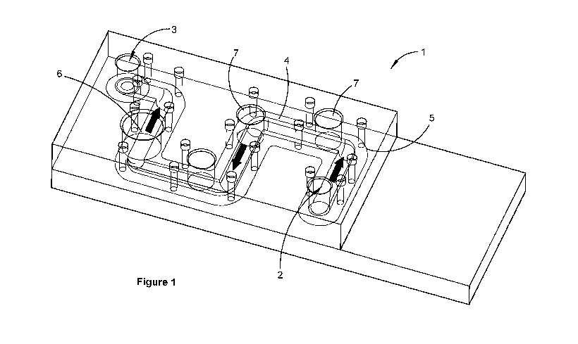
[0036] Figure 1 is a perspective view of a manifold in accordance with a
first
embodiment of the invention;
[0037] Figure 2 is a perspective view showing the internal volume of
another manifold
in accordance with the invention forming the internal channel;
[0038] Figure 3 is a cross sectional view of the channel shown in Figure 2;
[0039] Figure 4 is a plan view of a manifold in accordance with another
embodiment of
the invention;
[0040] Figure 5 is a top view graphical representation of the resultant
wall shear
mapped onto the channel surface in accordance with Example 1, wherein the
channel
includes a 90 degree elbow bend and the Figure includes a shading key
indicating ranges
of wall shear;
[0041] Figure 6 is a side view graphical representation of the resultant
wall shear
mapped onto the channel surface in accordance with Example 2, wherein the
channel
includes a nozzle and the Figure includes a shading key indicating ranges of
wall shear;
[0042] Figure 7 is a top view graphical representation of the resultant
wall shear
mapped onto the channel surface in accordance with Example 2;
[0043] Figure 8 is a cross-sectional view of the manifold channel of
Example 2;
[0044] Figure 9 is a top view graphical representation of the resultant
wall shear
mapped onto the channel surface in accordance with Example 3, wherein the
channel
includes a 90 degree elbow bend and a nozzle, and the Figure includes a
shading key
indicating ranges of wall shear;
[0045] Figure 10 is a top view of the internal volume of the manifold
channel surface of
Example 3;
[0046] Figure 11 is a side view of the internal volume of the manifold
channel surface
shown in Example 3;
CA 02892272 2015-05-22
WO 2014/078910 PCT/AU2013/001359
- 7 -
[0047] Figure 12 is a top view graphical representation of the resultant
wall shear
mapped onto the channel surface in accordance with Example 4, wherein the
channel
includes a 45 degree elbow bend and a nozzle, and the Figure includes a
shading key
indicating ranges of wall shear;
[0048] Figure 13 is a top view graphical representation of the resultant
wall shear
mapped onto the channel surface in accordance with Example 5, wherein the
channel
includes a 135 degree elbow bend and a nozzle;
[0049] Figure 14 is a top view graphical representation of the resultant
wall shear
mapped onto the channel surface in accordance with Example 6, wherein the
Figure
includes a shading key indicating ranges of wall shear;
[0050] Figure 15 is a top view graphical representation of the resultant
wall shear
mapped onto the channel surface in accordance with Example 7;
[0051] Figure 16 is a top view graphical representation of the resultant
wall shear
mapped onto the channel surface in accordance with Example 8, wherein the
Figure
includes a shading key indicating ranges of wall shear;
[0052] Figure 17 is a top view graphical representation of the resultant
wall shear
mapped onto the channel surface in accordance with Example 9, wherein the
Figure
includes a shading key indicating ranges of wall shear;
[0053] Figure 18 is a top view graphical representation of the resultant
wall shear
mapped onto the channel surface in accordance with Example 10, wherein the
Figure
includes a shading key indicating ranges of wall shear;
[0054] Figure 19 is a top view graphical representation of the resultant
wall shear
mapped onto the channel surface in accordance with Example 11, wherein the
Figure
includes a shading key indicating ranges of wall shear;
[0055] Figure 20 is a top view graphical representation of the resultant
wall shear
mapped onto the channel surface in accordance with Example 12, wherein the
Figure
includes a shading key indicating ranges of wall shear;
CA 02892272 2015-05-22
WO 2014/078910 PCT/AU2013/001359
- 8 -
[0056] Figure 21 is a top view graphical representation of the resultant
wall shear
mapped onto the channel surface in accordance with Example 13, wherein the
Figure
includes a shading key indicating ranges of wall shear;
[0057] Figure 22 is a top view of a manifold having a plurality of sensor
ports in
accordance with the invention;
[0058] Figure 23 is a series of views depicting alternative forms of
deflection formation
in accordance with the invention; and
[0059] Figure 24 is a venturi type deflection formation in accordance with
the invention.
PREFERRED EMBODIMENTS OF THE INVENTION
[0060] The invention is directed toward a fouling resistant manifold for
mounting a fluid
monitoring sensor used to monitor various fluid parameters of a fluid flowing
within a fluid
channel of the manifold.
[0061] One preferred embodiment of the invention is shown in Figure 1. The
manifold
1 includes a fluid inlet 2 and a fluid outlet 3 connected by a fluid channel
4. A manifold
wall 5 having an inner channel surface 6 defines the fluid channel 4. The
manifold
includes at least one sensor mounting area or, as shown in Figure 1, a
plurality of sensor
mounting areas 7. To facilitate sensor exposure to the fluid in the channel,
each sensor
mounting area 7 may be provided with at least one aperture or port in the
manifold wall 5.
Of course, some types of sensor may not require direct contact with the fluid
and may
operate equally well through the manifold wall. While Figure 1 shows a single
port at
each mounting area, multiple ports and/or sensors may be located at each of
the sensor
mounting areas.
[0062] Figure 2 displays another preferred embodiment of the invention.
However, in
this figure for clarity, the manifold and manifold wall 5 have been removed to
reveal the
shape of the three dimensional channel 4 as a volume that is defined by the
inner surface
6 of the omitted manifold wall 5. This volume also represents the
channel/manifold wall
interface and as such, the inner surface 6 of the channel as defined by the
manifold wall.
The manifold is configured for fluid flow from the inlet 2 to the outlet 3.
The position of a
sensor mounting area 7 is shown on the surface of the channel 4.
CA 02892272 2015-05-22
WO 2014/078910 PCT/AU2013/001359
- 9 -
[0063] It will be appreciated that it is the shape of the channel 4 defined
by the
manifold rather than the external shape or appearance of the manifold which is
significant
in determining the internal flow characteristics of the manifold. Hence the
figures used in
the examples presented below display the shape and dimensions of the channel
volume
as would be defined by a respective manifold.
[0064] The term "manifold" as used herein is intended to convey any flow-
through
conduit on which a sensor is mounted thereby providing the sensor with
exposure to the
fluid. As such "manifold" would equally include any section of a main line
conduit for
mounting a sensor, as well as an auxiliary conduit arrangement specifically
designed for
drawing a portion of fluid from a main flow line to be presented to the sensor
and then
returned to the main flow, or otherwise. The manifold or conduit in this
context may
therefore have one or more fluid inlets and one or more fluid outlets.
[0065] Furthermore, the term "exposure" includes any operational exposure
as
required by a sensor in order to function effectively as intended. "Exposure"
may
therefore include physical contact with the fluid flow or exposure by close
proximity
through an optically transparent window or the manifold wall. The type of
exposure
required will depend on the operational characteristics of the particular
sensor.
[0066] Referring to Figure 2, the manifold channel 4 defines a fluid flow
path from the
fluid inlet 2 to the fluid outlet 3. A flow deflection formation 9 is included
to control the
flow characteristics of the fluid in selected regions of the channel. In
particular, the
deflection formation is disposed upstream of the respective sensor mounting
area 7 to
accelerate a stream of the fluid. The resultant change in velocity gradient of
the fluid
stream caused by the acceleration of the fluid induces a localised increase in
shear stress
immediately adjacent the manifold wall, referred to as wall shear, at
predetermined
sensor mounting area 7 of the channel surface 6. The flow deflection formation
is also
configured to minimise direct impact of fouling material onto the sensor
mounting area
and therefore the sensor surfaces.
[0067] Wall shear in respect of the invention refers to shear stress that
the moving fluid
(with a substantially constant viscosity) imparts onto the inner surface of
the wall defining
the channel, at a specified location. It has been found that increasing the
wall shear
reduces the tendency for suspended matter in the fluid to attach to the
channel surface
and also may provide a cleaning effect by dislodging any matter that does
accumulate.
CA 02892272 2015-05-22
WO 2014/078910 PCT/AU2013/001359
- 10 -
[0068] Clearly the invention may not eliminate fouling in all situations
because the
tendency for fouling depends on a range of factors including but not limited
to the nature
of the fluid, the overall flow rate of the fluid and channel diameter, the
surface properties
of the channel wall, the inherent stickiness of the fouling matter,
temperature, viscosity
etc. The aim of the invention is, however, to employ a deflection formation in
the channel
upstream of the sensor mounting area to induce an increase in the average wall
shear
exerted on the manifold wall within the sensor mounting area when compared to
the
average wall shear exerted on the manifold wall within the same sensor
mounting area in
the absence of the deflection formation, thereby reducing the propensity for
fouling in the
vicinity of the sensor.
[0069] The deflection formation 9 may take a variety of forms including one
or more of:
an elbow bend in the manifold channel; a constriction of the channel; a
venturi formation;
baffles, deflection surfaces, vanes and/or fins; modifications to the channel
cross-section
shape or profile of the internal surface 6; channel ribbing or rifling; a
nozzle; and/or other
features, formations or devices, adapted individually or in combination to
induce the
specified effect on the fluid in the vicinity of the sensor mounting area.
[0070] For instance, fluid flow around an elbow bend is rarely uniform and
usually
includes different areas of fluid flowing at comparatively different speeds
and directions.
In the context of the invention, the uneven flow distribution is exploited to
provide
increased levels of wall shear at particular locations in the channel
downstream of the
bend. Similarly, venturi formations or channel constructions can be used to
increase
dynamic pressure all wall shear at particular areas. Vanes, fins, surface
formations and
channel shapes can be used to direct fluid within the channel, to create
defined areas of
increased wall shear, while nozzles may be used to direct a comparatively high
velocity
jet of fluid, with respect to the baseline flow in the channel, over targeted
sensor mounting
areas. Accordingly the shear stress induced at the sensor mounting area is
greater than
the average shear stress imparted to the manifold wall within the manifold.
[0071] The invention may be used for a wide variety of sensors for
monitoring various
parameters of the fluid flowing through the manifold. Such sensors include but
are not
limited to sensors for monitoring fluid: flow rate, temperature, pressure,
viscosity, acidity
(pH), transparency, dissolved oxygen (DO) concentration, oxidation reduction
potential
(ORP) and/or turbidity.
CA 02892272 2015-05-22
WO 2014/078910 PCT/AU2013/001359
- 11 -
[0072] Various examples of flow deflection formations are shown in Figure
23. Figure
23A displays a stepped reduction nozzle or plug insert of length LN, outside
or inlet
diameter of di and outlet diameter of do. In this particular embodiment, LN is
around 5cm
while di and do are around 1.5cm and 1 cm respectively.
[0073] Figure 23B shows a conical nozzle with circular inlet/outlet. The
nozzle tapers
from the inlet to the outlet thereby reducing the cross sectional area of the
channel/nozzle
by a nozzle reduction ratio. For instance, a circular channel and nozzle as
shown in
Figure 23B has a nozzle reduction ratio given by (d1/d0)2. In one embodiment,
for
instance, di is around 15.3 mm while do is around 4 mm providing a nozzle
reduction ratio
of 14.6 or around 15. It is also noted that the nozzle outlet is generally
centrally, coaxially
positioned in the channel.
[0074] Figure 230 shows a similar conical reduction nozzle. However the
outlet of the
nozzle in this case is offset from the channel centre. The nozzle outlet in
Figure 230 is
circular while the nozzle shown in Figure 23D includes a rectangular outlet.
[0075] Figure 23E shows a nozzle having a stepped reduction in cross
section and
includes an outlet generally perpendicular to the longitudinal axis of the
channel. Figure
24 is a venturi type device.
[0076] It will be appreciated that while the examples shown in Figures 23
and 24 are
illustrated as plug inserts to be inserted into a channel of corresponding
diameter, they
could equally be formed integrally with the channel wall as part of the
manifold. These
formations may also be used in conjunction with other complementary flow
deflection
devices, such as specifically configured pipe bends, and/or internal channel
profiles, to
induce the desired flow characteristics in the vicinity of the sensor mounting
area, as
described more fully below. The manifold is thereby resistant to the effects
of sensor
fouling and consequentially reduced flow rates, advantageously allowing it to
operate for
comparatively extended periods without maintenance and/or cleaning. In this
regard,
while the invention may be used for a wide range of fluids, its potential
advantages may
only be realised when used in conjunction with fluids which by nature are
prone to fouling
the conduits in which they flow. As previously noted, such fluids include but
are not
limited to sewage, effluent and grey water which require long-term and
constant
monitoring for effective management. Many of these types of fluids include
greasy and/or
fatty fouling material that along with microorganisms and biofilms are prone
to
CA 02892272 2015-05-22
WO 2014/078910 PCT/AU2013/001359
- 12 -
accumulating on the internal surfaces of pipes and the manifolds in or to
which sensors
are mounted.
[0077] Turning now to describe the apparatus in more detail, the sensor
mounting area
7 includes a sensor mounting port for mounting a sensor. Preferably, the
mounting area
is a generally flat surface which can be advantageous for aligning and
mounting the
sensor flush with the inner channel surface. However, providing a flat sensor
mounting
surface may also influence the shape of the channel. For instance, Figure 3
displays a
sectional view of the channel 4 in one form of the invention.
[0078] The channel in this embodiment is generally circular, however as
illustrated,
has a generally D-shaped cross section comprising a rounded semi-circular
portion 10, at
the bottom as shown on the page, and an upper, squarish portion 11 including a
generally
flat section 12. While other shapes may be used, here, the flat section 12
provides the
channel with a generally planar surface for sensor mounting while the opposing
rounded
side of the manifold is volumetrically efficient and also, as will be seen,
can enhance
vortex flow generation following a bend in the manifold by acting as a
deflection surface,
particularly in combination with the planar top surface. Otherwise, the width
and height of
the channel are generally equivalent. As such, the channel can be referred to
herein as
having a diameter D although it may not strictly have a circular cross
section.
[0079] As shown in Figure 2, the generally flat planar surface may extend
over the
length of the channel to provide a channel having a constant cross section.
However, it
will also be appreciated that this may not always be the case and that in some
embodiments, the cross section of the channel may vary significantly along its
length.
For instance, the channel may include a portion for sensor mounting comprising
a length
of channel having a U-shaped cross-section, and revert to a volumetrically
efficient
circular cross section for the remaining portion of the manifold.
[0080] The channel shown in Figures 2 and 3 provides for comparatively easy
sensor
access from above. However the sensors could alternatively be mounted and/or
the
planar surface provided, at any orientation as required. For instance,
inverting the
manifold would present the planar sensor mounting surface facing downward
thereby
providing access from underneath.
CA 02892272 2015-05-22
WO 2014/078910 PCT/AU2013/001359
- 13 -
[0081] As noted, the deflection formation may take a variety of forms, and
may
comprise one or more elements, used in combination or separately. In one form
the
deflection formation is a simple elbow bend 13 in the fluid channel. In
another form, the
deflection formation is a fluid nozzle or internal jet 14. In still further
embodiments, as
shown in Figure 2, a combination of an elbow bend and a nozzle is used.
[0082] Figure 4 shows an embodiment of the manifold having both an elbow
bend and
an internal fluid nozzle. The direction of flow is indicated by arrow (F). As
can be seen,
fouling matter (M) impinges and accumulates near the entrance to each bend,
while a
zone of increased wall shear is generated after the bend exit. The increased
level of wall
shear results in an inherent cleaning effect on the inner surface shown as
clean zone
(CZ). Locating the sensor mounting area 7 and the sensors in the clean zone of
increased wall shear, prevents or reduces the tendency for build-up of
material on the
sensor.
[0083] As a starting point, testing of the embodiments of the manifold
demonstrated
that cleaning of the channel walls occurred at 15-25 I/min for a bare elbow
and 6-8 I/min
for a nozzle and elbow in combination. Computational Fluid Dynamics (CFD)
analysis
was used to illustrate ranges, in terms of physical size, elbow angle and flow
rate, over
which the same cleaning action can be reproduced in the channel. In this and
all
examples herein, the fluid is assumed to be Newtonian having a viscosity of
water.
Examples
[0084] It is not possible to illustrate every conceivable form of the
manifold. However,
in support of the invention, several illustrative examples are now presented
and
summarised in the table below.
Example Nozzle Pipe Elbow Separation Flow Note
Height Diameter Angle [s] [mm] Rate
[h] [mm] [0] [I/min]
1 Nil 15.3 90 N/A 22 Baseline
2 Slit (1mm)* 15.3 0 10 8 Nozzle
3 Slit (1mm) 15.3 90 10 8 Bend + Nozzle
4 Slit (1mm) 15.3 45 10 8 Elbow bend
Slit (1mm) 15.3 135 10 8 angle
6 Slit (0.5mm) 7.65 90 5 2 X0.5
7 Slit (10mm) 153 90 100 800 X10
8 Slit (10mm) 153 90 10 800 X10
9 Slit (1mm) 15.3 90 10 4 Flow Rate
Slit (1mm) 15.3 90 10 6
CA 02892272 2015-05-22
WO 2014/078910 PCT/AU2013/001359
- 14 -
11 Slit (3mm) 15.3 90 10 6 Flow rate with
12 Slit (3mm) 15.3 90 10 8 larger nozzle
13 Slit (3mm) 15.3 90 10 12 outlet
* Nozzle is placed along the top flat wall
Example 1: Baseline case - Simple elbow bend - Figure 5
[0085] In order to quantitatively define the level of cleaning, a
simulation was first
performed for the bare elbow case at fluid flow rate of 22 I/min. The channel
used in this
example is shown in Figure 5 where fluid flows from the inlet 2 to the outlet
3 and
includes elbow bend 13. The channel is divided by the bend into an inlet
section of length
Linlet and an outlet section of length Loutlet. In the embodiment shown Linlet
is 8cm and
Loutiet. is 6cm.
[0086] The cross-section of the channel is constant and is shown in Figure
3. Here the
radius (r) of the semi-circular portion is 7.65mm providing a diameter (D)
which
determines the width of the channel as 15.3mm. The height (z) of the square
portion is
5.8mm and each radius r, of the chamfered corners is 2mm. The bend is
preferably 90
degrees but bends of between 45 degrees and 135 degrees may also be applied as
will
be seen.
[0087] The simulated distribution of wall shear stress (t) is plotted on
the channel walls
with ranges in Pa as shown by the Wall Shear key. The area of interest is the
sensor
mounting area 7 immediately downstream of the bend. Accordingly the sensor
mounting
area is divided into zones, increasing in distance from the bend. In Figure 5,
three
equally sized zones have been predetermined with boundaries selected at
equally
increasing distances from the bend. Distances from the bend exit are expressed
as a
function of the diameter D of the channel 4 so as to be scalable with respect
to the
channel dimensions.
Zone A - OD to 0.65D (Ocm to 1cm)
Zone B - 0.65D to 1.3D (1cm to 2cm)
Zone C - 1.3D to 2D (2cm to 3cm)
[0088] Each of these zones is area-averaged over three individual zones
positioned at
0-1 cm, 1-2 cm and 2-3 cm downstream of the elbow on the flat section of the
channel
wall (see Figure 1 for an example). The bend exit is taken to be the point
where the
CA 02892272 2015-05-22
WO 2014/078910 PCT/AU2013/001359
- 15 -
channel transitions from a bend or curve to a straight section. These zones
represent
possible sensor locations. The maximum averaged wall shear value was then used
as a
benchmark (Tcnt) to assess the level of cleaning in all subsequent simulations
for different
channel designs. A t value exceeding icnt is then considered to provide
stronger cleaning
than that experimentally observed in a bare elbow at high flow (>22 I/min).
[0089] In Figure 5, ranges of wall shear are mapped on the surface of the
channel with
shading. The darker areas display higher wall shear values, whilst the lighter
areas are of
lower shear stress as indicated by the key.
[0090] From the figure, it can clearly be seen that a zone of comparative
higher wall
shear is generated after the exit of the bend. As noted above, the wall shear
is caused by
uneven distribution of flow velocity in the channel immediately downstream of
the bend,
partially enhanced by the fluid in the bend striking the curved lower rear
channel wall of
the bend and being deflected upwardly. It is noted that the asymmetrical cross
section of
the channel means that this deflection effect provided by the lower side wall
is not
balanced by an equal but opposite deflection of the upper sidewall. The
increased level
of wall shear results in a reduction of the tendency for the channel surface
to accumulate
fouling matter in that area.
[0091] While the figure shows the pattern of wall shear values mapped onto
the
channel surface, the averaged wall shear is also calculated for each of Zones
A, B and C.
In this regard the channel generates an average wall shear of 34 Pa in both
Zone A and
Zone B. This value is known to reduce fouling in real test cases. Accordingly,
it is used
as a baseline critical value for the wall shear (T,,,t) in all subsequent
examples. Wall shear
above icnt is considered sufficient to reduced or eliminate fouling build up.
[0092] At 22 I/min, the predicted pressure drop is 2.2 kPa.
Example 2: Internal Nozzle - Figures 6, 7 & 8
[0093] As noted, in another form, the deflection formation is an internal
fluid nozzle 14.
The nozzle is configured to direct fluid to generate higher shear in the
sensor mounting
area 7.
CA 02892272 2015-05-22
WO 2014/078910 PCT/AU2013/001359
- 16 -
[0094] An
example of an internal fluid nozzle is shown in Figures 6, 7 and 8 which
show respective side, top and cross sectional end views of a straight channel
of generally
uniform cross-section other than the nozzle section, as will be explained. The
cross¨
sectional profile of the channel shown in Figure 8 is identical to that from
Example 1 and
shown in Figure 3.
[0095] In
this configuration, a nozzle 14 includes a tapered section between a nozzle
inlet 15 and a nozzle outlet 16. The taper is generally formed by the
intersection of an
angled planar surface 17 with the channel which acts as a ramp of length LN
extending
along the length of the channel. As can be seen in Figure 8 the nozzle outlet
16 is
formed as an elongate slit positioned adjacent the planar channel wall. In
this
embodiment LN is 5cm and the ramp begins 2cm downstream of the inlet at the
bottom or
semicircular portion and is angled toward the square, upper portion of the
channel ending
1 mm before the channel roof thereby forming the nozzle outlet as a slit 1mm
in height
(h=1mm) with a cross sectional area of 12.5mm2. The sensor mounting area 7 is
positioned by separation distance s, 1cm downstream of the nozzle and is split
into zones
A, B and C as per Example 1.
[0096] The
reduction in cross-sectional area in the nozzle causes an increase in fluid
flow velocity and wall shear stresses. These were recorded in Zones A, B and C
as 170,
125 and 90 Pa respectively which are all well above the calculated minimum
value of 34
Pa for icnt. It should also be noted that these high values of wall shear were
simulated at
a reduced flow rate of 8 I/min (down from 22 I/min in Example 1).
Example 3: Offset Nozzle, Elbow and Defection Surface - Figures 9, 10 & 11
[0097] As
previously noted the combination of a nozzle and a bend is also
contemplated and shown in Figure 9. In this example, the nozzle 14 is fitted
1cm
upstream of a 90 degree bend 13. However in contrast to Example 2, the nozzle
outlet
16 is configured adjacent the semicircular portion of the channel wall (i.e.
opposite the
sensor side).
[0098]
Otherwise the nozzle dimensions are the same as for Example 2, where nozzle
length LN is 5cm and the nozzle outlet is 1mm in height (h=1mm) with a cross
sectional
area of around 12.5mm2. Separation distance s now becomes the nozzle outlet-
bend
entry displacement but remains at 1cm.
CA 02892272 2015-05-22
WO 2014/078910 PCT/AU2013/001359
- 17 -
[0099] The channel example 3 is shown in Figure 9. Here the length Loutiet
of the outlet
section of the channel, after the bend, is 12cm. Figures 10 and 11 show
partial views of
the channel from the top and side respectively. The exit portion of the
channel has been
shortened in Figure 10.
[0100] In this configuration, the offset nozzle directs a thin accelerated
stream of fluid
onto the lower, transverse channel wall at the exit of the bend. The stream
sweeps along
the channel wall, directly raising wall shear stress along its path. The
curved shape of the
circular wall in combination with the outer periphery of the bend acts as a
deflection
surface deflecting the stream upwardly and into the bend exit, initiating a
"swirling" or
vortex flow around the bend and in the channel downstream of the bend,
generally raising
the velocity of the fluid adjacent the manifold wall. The vortex is strongest
immediately
after the bend and particularly at the top planar surface mounting area,
dissipating with
increasing distance from the bend. However, the higher wall shear stress
region
persisted for more than 5 channel diameters downstream of the elbow.
Accordingly,
while the sensor mounting area provides the strongest cleaning action at Zone
A of the
sensor area, the cleaning effect and potential sensor mounting area is
feasible within
area B and C and up to 7.5cm from the bend (5 times D).
[0101] The average values of wall shear in Zones A, B and Care 215, 178 and
67 Pa
respectively which again are all well above the calculated minimum value of
icnt 34 Pa.
As with example 2, it is noted that these high values of wall shear were
simulated at a
reduced flow rate of 8 I/min (down from 22 I/min in Example 1). By comparison,
although
not presented herein as an example, placing the nozzle at the top flat side
produces
stronger cleaning in Zone B.
Examples 4 & 5: 45 and 135 degree elbow angle - Figures 12 & 13
[0102] Examples 4 and 5 display the effect of the angle of the bend 13 of
the elbow.
The channel of Example 4 as shown in Figure 12 uses a combination bend and
nozzle as
per Example 3, however the channel includes an acute bend angle of 45 . In
Example 5,
shown in Figure 13, the bend angle is 135 .
[0103] The wall shear values are mapped onto the respective 45 degree bend
and 135
degree bend channels in Figures 12 & 13.
CA 02892272 2015-05-22
WO 2014/078910 PCT/AU2013/001359
- 18 -
[0104] The average values of wall shear in Zones A, B and Care presented in
the
table below. It is noted that in contrast to all other Examples, the average
shear values
increased from Zone A to Zone C in Example 4.
Example 4 Example 3 Example 5
Bend angle Bend angle Bend angle
(45 degrees) (90 degrees) (135 degrees)
Figure 12 Figure 9 Figure 13
Zone C (t) / Pa 175 67 110
Zone B (t) / Pa 162 178 138
Zone A (t) / Pa 129 215 159
[0105] Both acute and obtuse angles reduce the peak shear value. However,
the
benefit is a more uniform distribution of high wall shear across all three
zones. For the
45 elbow case (Figure 12), the high wall shear region elongated slightly and
occurs
further downstream of the bend whereas the 135 case in Example 5 shows the
higher
shear occurring closer to the bend.
Example 6 & 7: Scale effect - Figure 14 & 15
[0106] The channel and the nozzle were scaled down by a factor of 1/2 in
Example 6 as
shown in Figure 14 and up by a factor of 10 in Example 7 (Figure 15). A
comparative
table of dimensions of the channels used in Examples 6 and 7, as compared to
Example
3, is presented below.
Example 6 Example 3 Example 7
Scale (1/2 x) Scale (1x) Scale (10x)
Figure 14 Figure 9 Figure 15
Radius (r) / mm 3.825 7.65 76.5
Height (z) / mm 2.9 5.8 58
Lmiet mm 40 80 800
Loutiet mm 30 60 600
Separation (s) / mm 5 10 100
Zone A / mm 0-5 0-10 0-100
Zone B / mm 5-10 10-20 100-200
Zone C/ mm 10-15 20-30 200-300
[0107] The simulated distribution of wall shear stresses (t) is plotted on
the channel
walls and shown in Figure 14 and Figure 15. It should be noted that Figures 14
and 15
are not drawn to comparative scale.
CA 02892272 2015-05-22
WO 2014/078910 PCT/AU2013/001359
- 19 -
[0108] In order to maintain the same fluid flow velocity inside the
channel, due to the
increase of cross-sectional area, the flow rate was necessarily scaled down
and up by
factors of 1/4 and 100, respectively. Thus the flow rate in Example 6 is 2 1/m
and 800 l/min
in Example 7.
[0109] As can be seen with reference to the figures, the wall shear pattern
is relatively
similar as between Examples 3, 6 and 7 in that the high wall shear stress
regions are
located within the sensor area and particularly Zones A and B, dropping in
Zones C.
Example 6 Example 3 Example 7
Scale (1/2 x) Scale (1x) Scale (10x)
Figure 14 Figure 9 Figure 15
Zone C (t) / Pa 65 67 58
Zone B (t) / Pa 162 178 121
Zone A (t) / Pa 204 215 129
[0110] In all cases, the averaged wall shear peaked in Zone A. However, the
value is
smaller at larger (x10) scale (Example 7), indicating that the underlying flow
pattern does
not scale up linearly with channel size and hence the wall shear level does
not remain the
same for a larger channel diameter. Nevertheless, the averaged wall shears
within the
three windows were all well above icnt for the three channel diameters tested.
It is
therefore reasonable to expect effective cleaning of the channel wall for
channel
diameters ranging between around 7 mm and at least around 150 mm. It is
important to
note that sizes of the zones were also scaled relative to the channel.
Example 8: Reduced slit to bend distance - Figure 16
[0111] One of the effects of the non-linear nature of the scaling is shown
in Example 8.
With reference to Example 7, due to the scaling, the separation distance s
between
nozzle and bend in the x10 case (Example 7) is 10 cm rather than 1cm as for
the base
scale (x1) case in Example 3. Accordingly, dissipation of the stream of fluid
from the
nozzle is a greater factor at 10 cm than it is with a smaller separation
distance s, leading
to weaker cleaning downstream of the elbow. In Example 8, shown in Figure 16,
the
nozzle separation distance s is reduced by a factor of 10-1 to 1cm.
CA 02892272 2015-05-22
WO 2014/078910 PCT/AU2013/001359
- 20 -
[0112] The plotted results are presented in Figure 16 and summarised in the
table
below. It can be seen that reducing the scaled separation distance s (i.e.
from 10cm to
1cm upstream of the elbow) reduces spreading and stream decay wall shear,
particularly
within Zone A (Figure 16). The average wall shear in each zone A, B and C are
presented below. The results of Example 7 are included for comparative
illustration.
Example 7 Example 8
Scale (10x) Scale (10x)
d = 100mm d = 10mm
Figure 15 Figure 16
Zone C (t) / Pa 58 58
Zone B (t) / Pa 121 117
Zone A (t) / Pa 129 168
Example 9 and 10: Effect of flow rate - Figures 17 & 18
[0113] With reference to the average shear in each zone in the previous
examples, it is
noted that all average values comfortably exceed the minimum value of icnt (34
Pa)
determined as required for effective cleaning. Since flow rate directly
affects the level of
wall shear and hence cleaning downstream of the elbow, it should be possible
to reduce
the flow rate while maintaining adequate (but reduced) cleaning. Naturally
reducing the
flow rate requires less pumping pressure and pumping losses.
[0114] Examples 9 and 10 reduce the flow rate from 8 I/min in Example 3, to
4 and 6
I/min respectively whilst using the same channel dimensions as used in Example
3. The
channel dimensions in Example 9 & 10 are identical to those of Example 3.
[0115] The wall shear contours are presented in Figures 17 and 18. The
average wall
shear stress in each of Zones A, B and C are presented in the table below.
Again the
results of Example 3 are included for comparative illustration.
[0116] As can be seen in the table, at flow rates of 4 I/min the average
wall shear is
below Tait. in Zone C but above icrit. in Zone A and Zone B. This is
considered as the
minimum water flow rate required to clean Zone A and Zone B similar to that
observed for
a bare elbow at high flow rate in the laboratory. The required pressure drop
at 4 I/min is
15.9 kPa.
CA 02892272 2015-05-22
WO 2014/078910 PCT/AU2013/001359
- 21 -
[0117] Examples 9 & 10 indicate that pumping requirements may be reduced
whilst
still providing adequate cleaning performance.
Example 9 Example 10 Example 3
Flow Rate Flow Rate Flow Rate
(4 Umin) (6 Umin) (8 Umin)
Figure 17 Figure 18 Figure 9
Zone C (t) / Pa 17 38 67
Zone B (t) / Pa 46 101 178
Zone A (t) / Pa 59 126 215
Examples 11, 12 and 13: Effect of nozzle outlet size - Figures 19, 20 & 21
[0118] Another method for reducing pumping losses is to increase the size
of the
nozzle outlet. Examples 11, 12 and 13 each use a larger slit width h of 3mm
and flow
rates of 6, 8 and 12 I/min respectively.
[0119] The trade-off of the larger cross-sectional area of the slit is a
decrease in the
level of wall shear. The simulation results are presented in the table below
and shown in
the shaded plot in Figures 19, 20 and 21 corresponding to Examples 11, 12 and
13
respectively.
Example 11 Example 12 Example 13
Slit (h) 3mm Slit (h) 3mm Slit (h) 3mm
Flow Rate Flow Rate Flow Rate
(6 Umin) (8 Umin) (12 Umin)
Figure 19 Figure 20 Figure 21
Zone C (t) / Pa 20 35 76
Zone B (t) / Pa 24 41 86
Zone A (t) / Pa 24 42 90
[0120] The results show that to achieve -cum the channel needs to operate
at a
minimum flow rate of 8 I/min. Variation in the averaged wall shear across the
three
windows is less than 17% as compared to 72% in the 1 mm slit case (Figure 6).
The
pressure drop required at 6, 8 and 12 I/min is 3.9, 6.9 and 15.5 kPa,
respectively.
CA 02892272 2015-05-22
WO 2014/078910 PCT/AU2013/001359
- 22 -
Manifold working range
[0121] Based on the above examples, working ranges of the channel with an
elbow
and slit nozzle have been established in the table below.
Minimum Maximum Optimum (the
parameter that
works best in the
tested system)
Diameter of Pipe (D) [mm] 7.65 153 15.3
Flow Rate [I/min]
4 8 >4
(15.3mm channel, 1mm slit)
Flow Rate [I/min]
8 12 >8
(15.3mm channel, 3mm slit)
Elbow turning angle (in system that
45 1350 90
has an elbow)
Distance from end of the slit to the 0.065D 0.65D
<0.65D
beginning of the elbow (153mm case) (15.3mm case)
Distance from the end of the elbow
0.33D
to the centre of the clean OD >2.5D (1.3D)
(5mm/15.3mm)
zone/sensor location
D = channel diameter (15.3mm for X1 case)
[0122] Referring to the table, in an optimised example of the invention the
manifold
channel is generally circular or square in cross section. The diameter (or
maximum
width) D of the channel is between around 7mm and 15cm.
[0123] The manifold includes a composite deflection formation comprising
two discrete
but synergistically interactive deflection elements; an elbow bend and an
upstream nozzle
defining a nozzle outlet for directing a stream of liquid adjacent and along a
wall of the
channel and into the bend. The nozzle outlet is spaced from the bend by a
distance of
between 0 and around 0.65 times the channel diameter D.
[0124] The bend provides a directional change of the channel in an angular
range of
around 45 and around 135 . The nozzle provides a reduction ratio,
corresponding to the
ratio of the cross-sectional area of the channel to the cross-sectional area
of the nozzle
outlet, of between 4 and around 15. The nozzle outlet is preferably elongate
having a
transverse width of between 0.03D and around 0.2D. The sensor mounting area is
disposed adjacent and immediately downstream of the elbow bend exit, within a
distance
corresponding to 5 times the diameter D of the channel.
CA 02892272 2015-05-22
WO 2014/078910 PCT/AU2013/001359
- 23 -
[0125] In one form, the manifold may be connected to a primary fluid
conduit to define
an auxiliary flow path such that only a proportion of fluid is drawn from the
primary flow
and directed through the manifold, for monitoring. Fluid may be drawn off
passively by
relying upon pressure differentials and/or flow in the primary conduit, or
actively by use of
a fluid pumping device. In another form, the manifold is incorporated into, is
integral with,
or simply constitutes part of, the main conduit.
[0126] Figure 22 shows a manifold design in accordance with the invention
which is
suitable for a plurality of sensors. By alternating the direction of
successive bends the
manifold defines a serpentine flow path, incorporating multiple sensor
mounting areas,
within a relatively compact topography.
[0127] More specifically, the manifold passageway 4 includes four sensor
mounting
areas 7 each having a respective sensor mounting port and sensor module 17. It
is noted
that each of the sensor mounting areas is located after a respective
deflection formation
in the form of a respective elbow bend 13. While this particular manifold does
not include
nozzle type deflection formations, the manifold could be modified to include
one or more
formations associated with one or more sensor mounting areas.
[0128] The fluid inlet 2 is connected by means of hose 18 to the outlet of
a fluid pump
19. The pump 19 draws fluid from a fluid source to be monitored. Pump inlet 20
can be
seen, which may be connected by means of a hose (not shown) to a tank or
reservoir, or
a bleed from a primary fluid pipe. Another hose (not shown) connects the
manifold outlet
3 by means of fitting 21 to return fluid to the source or primary supply. In
other cases the
pump may not be required and instead the fluid flows through the manifold due
to
pressure differentials at the inlet 2 and outlet 3.
[0129] The invention in its various preferred embodiments provides a
manifold for
directing a fluid to a sensor mounted on the manifold, in a unique manner that
both resists
fouling and avoids damage to sensitive sensors. This in turn minimises the
need for
maintenance and repairs. Advantageously, the apparatus works well for robust
sensors
in a variety of liquids including those containing greasy/fatty suspended
matter. It is also
suitable for sensors having flexible or otherwise sensitive fluid interfaces
(e.g. polymer
membranes) as it avoids direct flow impingement from wall jets that can
disrupt or
damage these sensitive surfaces. Moreover, these advantages can be achieved in
a
reliable and cost-effective manner, and at reduced flow rates than otherwise
might be
CA 02892272 2015-05-22
WO 2014/078910 PCT/AU2013/001359
- 24 -
required. The invention thus represents a practical and commercially
significant
improvement over the prior art.
[0130] Reference throughout this specification to "one embodiment" or "an
embodiment" means that a particular feature, structure or characteristic
described in
connection with the embodiment is included in at least one embodiment of the
present
invention. Thus, appearances of the phrases "in one embodiment" or "in an
embodiment"
in various places throughout this specification are not necessarily all
referring to the same
embodiment, but may. Furthermore, the particular features, structures or
characteristics
may be combined in any suitable manner, as would be apparent to one of
ordinary skill in
the art from this disclosure, in one or more embodiments.
[0131] Similarly it should be appreciated that in the above description of
exemplary
embodiments of the invention, various features of the invention are sometimes
grouped
together in a single embodiment, FIG., or description thereof for the purpose
of
streamlining the disclosure and aiding in the understanding of one or more of
the various
inventive aspects. This method of disclosure, however, is not to be
interpreted as
reflecting an intention that the claimed invention requires more features than
are
expressly recited in each claim. Rather, as the following claims reflect,
inventive aspects
lie in less than all features of a single foregoing disclosed embodiment.
Thus, the claims
following the Detailed Description are hereby expressly incorporated into this
Detailed
Description, with each claim standing on its own as a separate embodiment of
this
invention.
[0132] Furthermore, while some embodiments described herein include some
but not
other features included in other embodiments, combinations of features of
different
embodiments are meant to be within the scope of the invention, and form
different
embodiments, as would be understood by those skilled in the art. For example,
in the
following claims, any of the claimed embodiments can be used in any
combination.
[0133] In the description provided herein, numerous specific details are
set forth.
However, it is understood that embodiments of the invention may be practiced
without
these specific details. In other instances, well-known methods, structures and
techniques
have not been shown in detail in order not to obscure an understanding of this
description.
CA 02892272 2015-05-22
WO 2014/078910 PCT/AU2013/001359
- 25 -
[0134] Thus, although the invention has been described with reference to
specific
examples, it will be appreciated by those skilled in the art that invention
may be embodied
in many other forms.