Note: Descriptions are shown in the official language in which they were submitted.
CA 02892451 2015-05-25
1
APPARATUS FOR COLLECTION OF DEBRIS ESCAPING
AROUND A VEHICLE TAILGATE
CROSS REFERENCE TO RELATED APPLICATIONS
[01] This application claims priority to US Patent Application Serial No.
14/688,681 filed
April 16, 2015 and entitled "Apparatus for Collection of Debris Escaping
Around a Vehicle
Tailgate", which is a continuation-in-part of US Patent Application Serial No.
14/192,418 filed
February 27, 2014, entitled "Apparatus for Collection of Debris Escaping
Around a Vehicle
Tailgate" incorporating by reference and claiming priority to provisional
application Serial No.
61/770,463 filed February 28, 2013 and entitled "Apparatus for Collection of
Debris Escaping
Around a Vehicle Tailgate".
BACKGROUND OF THE INVENTION
[02] Briefly, the present invention relates to an apparatus for collection
and retention of debris
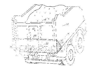
discharged or escaping around the tailgate of a vehicle such as a construction
vehicle, garbage
truck or the like.
[03] Highway safety is a continuing concern. Among the aspects of highway
safety is a
problem associated with vehicles, such as construction vehicles and similar
transportation
vehicles, which include a bed for the carriage of various materials.
Typically, such vehicles will
include a truck bed with a tailgate mounted to side walls of the truck bed.
The tailgate typically
opens in order to enable placement of materials on the bed or to enable
efficient discharge of the
materials from the bed. Such vehicles, when travelling on highways, may, due
to the irregularity
of the highway surface, discharge debris as the tailgate is displaced by
shaking or otherwise
moves causing escape or discharge of debris and other materials. Such
materials may also be
discharged due to the flow of air over the vehicle cab and around the
tailgate.
[04] A solution to this problem is addressed, for example, by U.S. Patent
No. 3,833,255
entitled "Combined Load Cover and Windshield Protector for Dump Truck"
incorporated
herewith by reference. There are often legal requirements that such covers be
provided for dump
trucks and other vehicles. However, such vehicles may still exhibit a
discharge of debris and
CA 02892451 2015-05-25
2
other material. Issues of this nature have also been addressed by other
patents such as U.S.
Patent No. 2,682,975 entitled "Dumping Box with Hinged Bottom Having Drip
Catching
Means" and U.S. Patent No. 2,679,335 entitled "Dribble Gate", both of which
are incorporated
herewith by reference. Further developments of this nature are directed to the
discharge of
debris through the slot between a pivoting tailgate and a truck bed. U.S.
Patent No. 5,046,774
entitled "Debris Catcher" addresses such issues and it, too, is incorporated
herewith by reference.
Another effort in this regard is disclosed in U.S. Patent No. 4,772,072
entitled "Dump Body
Debris Catcher" incorporated herewith by reference.
[05] Nonetheless, the cost of many of these solutions is significant and
there has remained the
desire to provide a lower cost, yet more highly efficient system to address
the issue of escape of
debris from dump trucks and other such vehicles. Additionally, a desirable
solution to such a
problem must consider the safety, the installation of a device, as well as the
aspect of simplicity
of use, storage of a device of this nature and application of the solution to
preexisting truck
configurations. Thus, the design for such an apparatus has presented an
ongoing problem with
respect to the aspects of safety, convenience and cost.
SUMMARY OF THE INVENTION
[06] Briefly, the present invention comprises an assembly of fabric panels
which are designed
to fit over a section of the tailgate and a portion of the bed of a truck in a
manner which covers
the opening or seam between a tailgate, the side walls and the bed of the
truck. The fabric may
be a mesh-like canvas similar to the type of covering that is often used for
covers placed over the
open top of a vehicle bay or bed such as a dump truck or the like. Such covers
typically are used
to cover a load of debris or materials carried in the bed of the dump truck or
transport vehicle.
The mesh-like canvas material is permeable to air thus allowing the passage of
air therethrough
from wind currents and other air flow due to drafting of the vehicle as it is
moving during its use
as a transport vehicle. A feature of the invention comprises a design to
prevent the device or
apparatus described from being engaged by air flow and detached from the
vehicle during travel
of the vehicle thereby damaging its effectiveness.
CA 02892451 2015-05-25
3
1071 Thus, it is an object of the invention to provide a cover which
has a design capable of
being easily maintained by attachment to a vehicle yet easily removed by a
vehicle operator
when necessary and reattached when necessary.
[08] It is a further object of the invention to provide a debris collection
device which is
compact, which may be folded for easy storage, and which is rugged and
inexpensive.
[09] Yet another object and feature of the invention is to provide a cover
which may be easily
attached to multiple sizes of vehicle truck beds having various sizes and
designs of tailgates
associated with the truck bed.
[10] Another object and feature of the invention is to provide a rugged yet
lightweight and
easily manipulated and adjustable cover device for collecting debris which
might otherwise
escape from the truck bed of a vehicle and thereby cause safety problems to
arise.
[11] These and other objects, advantages and features of the invention will
be detailed in the
description which follows that discusses and discloses an exemplary version of
the subject matter
of the invention.
BRIEF DESCRIPTION OF THE DRAWING
[12] In the detailed description which follows, reference will be made to
the drawing
comprised of the following figures:
[13] Figure 1 is an isometric view depicting an example of the invention as
incorporated and
positioned over the tailgate and bed of a carriage vehicle;
[14] Figure 2 is an isometric view of the apparatus for collecting and
retaining debris as
depicted in Figure 1;
[15] Figure 3 is an elevation view of one side end panel of the cover of
Figure 2;
[16] Figure 3A is an elevation view of the opposite side end panel depicted
in Figure 3;
[17] Figure 4 is an exploded view of the component parts of an alternative
embodiment of the
invention;
CA 02892451 2015-05-25
4
[18] Figure 5 is an elevation view of the embodiment of Figure 4 depicting
additional
features;
[19] Figure 6 is on isometric view of the embodiment of Figure 4 depicting
the attachment
thereof to a truck bed;
[20] Figure 7 is a plan view of a variation of the embodiment of Figure 4;
and
[21] Figure 8 is an isometric view of a variation of the embodiments
depicted in Figures 1-7.
DESCRIPTION OF EMBODIMENTS OF THE INVENTION
[22] Referring to the figures, Figure 1 depicts a vehicle of the type which
is a candidate for
use of the apparatus of the present invention. Thus, a truck 10 having a
vehicle bed assembly 12
with opposite, lateral side walls, such as walls 14, and an internal support
bed platform 16 further
includes an end tailgate 18. Typically, the tailgate 18 is pivotally mounted
to side walls 14 and
may swing about an attachment or connecting axis, may fold outwardly and/or
downwardly, or
may fold by means of hinges along one or the other of the vertical side walls
14. In some
instances, the tailgate 18 may incorporate a mechanism which provides tilting
and lowering so
that a load carried on the internal bed platform 16 of the truck 10 may be
placed on the gate as a
platform and lowered in order to remove the contents from the truck bed 16.
The subject matter
of the present invention is designed for utilization with multiple styles of
tailgate constructions
such as those discussed.
[23] The tailgate cover 20 of the invention includes a first generally
vertical, end panel 22 and
a second generally horizontal, end panel 24. The panels 22 and 24 are
generally rectangular and
include a common elongate generally horizontal seam or side 26. Vertical panel
22 includes
parallel, lateral sides 27, 28. The horizontal panel 24 includes generally
parallel lateral sides 29,
30. The panels 22 and 24 may be formed as separate elements which are stitched
together along
the seam or side 26 if desired. The panels 22 and 24 are typically of similar
size and dimension.
Typically, the side to side dimension of the panels 22 and 24 exceeds or is
generally equal to the
width of the bed 12 or the distance between the walls, such as walls 14 of the
vehicle 10. This is
an important aspect of the invention inasmuch as this aspect enables the
apparatus or cover of the
invention to be placed around the entire outside surface of the truck bed 12.
The size and
CA 02892451 2015-05-25
construction of the various panels enables reversal of the attachment of the
apparatus
embodiment depicted.
[24] The cover further includes end side panels 32, 34 that are
substantially identical in
configuration. In other words, they are generally congruent in configuration
and shape. For
example, end panel 34 has the configuration of an isosceles triangle having
side legs 38 and 40
which are equal and a base 42. In the embodiment depicted, the panels 32 and
34 are thus
substantially congruent and are in the form of an isosceles triangle. However,
other shapes may
be utilized in order to accomplish the goals and features of the invention,
for example,
rectangular panels which are attached to a generally horizontal and a
generally vertical end
panel. Among those goals and features is the aspect of fitting over and around
the sides of the
truck bed 12 as depicted, for example, in Figure 1.
[25] The legs or sides 38, 40 of the isosceles triangle shaped end panels
32 and 34 are
dimensioned to be substantially equal, respectively, to the side edges or side
dimension of panel
sides 27, 28, 29, 30. Thus, all of the component panels in the embodiment
depicted are stitched
together, though panels 22 and 24 may be formed from a single fabric sheet and
folded along the
longitudinal edge or seam 26 to form the configuration depicted in Figure 2.
[26] All of the seams or edges of the cover are folded over and stitched
with encapsulated
magnets, such as magnets 54 and 56 fitted into pockets in the folded over
cover material of edges
51, 53. The magnets 54, 56 may be of any desired configuration or shape. In
the embodiment
depicted, the magnets 54, 56 comprise elongate members or bars which are in
the range of 2 to 5
inches long and which are spaced from one another in the range of 2 to 5
inches around the
periphery of all of the seams and edges of the cover.
[27] The magnet retaining edges of the cover maintain the cover tightly in
place upon the
truck bed or body 12 as depicted in Figure 1. Because of the number of
magnets, their spacing,
and the fact that those magnets are maintained in the seamed portions or
portions which join the
separate panels as well as in the lateral edges and side edges 50, 52, 55, 26
of the panels, ensures
that multiple points of contact will be maintained between the cover and the
truck body. Thus,
CA 02892451 2015-05-25
=
6
the edges fit under the truck body or bed and are attached thereto as well as
along the vertical
walls 14 of the gate 18 as well as along side walls 14 and underside of bed
platform 16.
[28] The purpose of the cover is to fit over a gap 60 through which debris
and material may
discharge from the interior of the truck body 10. This gap 60 may vary in size
thus resulting in
the variance in particulates and materials which will sift therethrough or
pass therethrough.
Driving conditions may also affect the manner in which the gate 18 fits and
the tolerance of the
gate 18 may vary with respect to various types of vehicles. The cover of the
present invention
accommodates those variances. The cover, thus, retains debris which will fall
or exit from the
vehicle as a result of gravity, vibration and vehicle movement.
[29] The positioning of the magnets and the number of magnets, their
spacing and their
configuration all become beneficial elements with respect to the cover. That
is, their positioning
and the other features associated with the magnets including the feature
incorporating them
within pockets or folded over portions of the cover material enable the cover
to be molded tightly
against the body of the vehicle and enable the cover to provide a universal
fit to multiple types
and styles of vehicles. Consequently, the lateral width or lateral dimension
of the cover may
vary somewhat, yet still cover the gap 60 in a meaningful and functional
manner.
[30] Another feature of the means of attachment is that the cover may be
easily, manually
attached, rigidly attached, adjustably attached and easily removed by manual
operation. The
magnets can be individually detached in a manual fashion. Additionally,
because the cover is
made from a flexible material, the cover may be folded into a compact
configuration and the
magnets can be utilized to maintain the cover in the desired and folded
condition as a compact
package that can be stored easily. Attachment of the cover to a truck body is
also accommodated
by the design. That is, the upper row of magnets and the upper edge 28 of the
panel 22 may be
easily attached as a first effort with respect to attachment of the cover to
thereby position the
cover in a manner which will enable positioning of the other elements or
panels comprising the
cover.
[31] As an added feature of the invention, however, the triangular panels,
such as panel 30,
may include grommet openings, such as openings 70 and 72, to which a bungee
cord or rope can
CA 02892451 2015-05-25
7
be connected for retaining the cover in position. This may be useful with
respect to those truck
bodies which are manufactured from materials, such as aluminum, that are not
magnetic. As a
consequence, the cover of the present invention is capable of utilization with
multiple types of
truck bodies made from multiple materials. For example, as mentioned, aluminum
bodies may
utilize the cover. However, bodies which incorporate wood, for example, will
also be able to
utilize successfully the cover of the present invention. Thus, there are
various options and
alterations and changes and inclusions of alternative aspects of the invention
and substitution of
various components.
[32] The assembly or cover is reversible. That is, either side of panels
22, 24 may be fitted
against tailgate 18 and the seam 26 may be reversed in side to side alignment
from left to right or
vice-versa. Further, the magnets may be replaced since they may be retained in
pockets in the
fabric forming the cover by clips, or fasteners, or zippers.
[33] Figures 4-7 illustrate further embodiments, aspects and features of
the invention. In
Figures 4 and 5 panels 70, 72 is affixed or attached respectively to the
vertical side edge 27, 28
of the panel 22. The panels 70 and 72 may assume any desired shape. The
embodiments
depicted employ a generally rectangular shape for the panels 70, 72. Ropes or
bungee cords or
other attachment apparatus 74 may be affixed to the panels 70, 72 to augment
the attachment of
the cover to a vehicle. The panels 70, 72 may also include magnets.
[34] Figure 6 illustrates the manner of positioning of the generally
rectangular elongate panel
27 relative to a tailgate 18 between side walls 14 of a truck bed 16. The
tailgate 18 is attached to
and typically pivots about an axis transverse to the truck bed side walls 14.
Thus, when the bed
16 of a truck is filled with material and locked into position the cover
assembly is positioned
over lower part of the tailgate 18 and end of bed 16. However, due to
vibration and movement
of the component parts of the truck, debris such as sand, gravel and other
materials may "escape
between the pivotal tailgate 18, the side walls 14 and the truck bed 16".
Placement of the
substantially elongate panel 22 having a lower side edge 90 and an upper side
edge 92 is thus
effected and maintained by means of magnets as depicted by the array of
magnets 25 in Figure 5.
The side or lateral end panels 70 and 72 which are attached to the panel 22
along the seams 71
and 73 are also attached to the outside of respective side walls 14. The side
panels 70 and 72
CA 02892451 2015-05-25
8
thus are retained in a manner, such as described above, to tightly effect
wrapping the fabric panel
22 and closure of the spacing 60 between the tailgate 18 and the walls 14 as
well as the bottom
bed panel 16 of the truck bed. It is noted that panel 22 may have a vertical
dimension adequate
to cover the entire tailgate. The vertical dimension may be postulated by
evaluation of the
material being transported. That is finer particulate materials may
necessitate a panel which
covers the entire tailgate or extends over the top of the tailgate.
[35] Further as depicted in Figure 7 the embodiment of Figures 4, 5, and 6
may have
additional features. For example, the pane170 may include an array of magnets
such as magnets
94 and 96 for the side panels 70 and 72 respectively. The magnets 94, 96 are
augmented for
example, by bungee cords 74 or straps which hold the lateral side panels 70,
72 in position.
[36] An additional feature is inclusion of an auxiliary flexible material
panel 98 which is
attached to the generally rectangular lateral panel 22 along a seam 100. The
auxiliary panel 98
forms a generally coterminus seam 100 with bottom edge 90 of the panel 22.
Further, the
auxiliary panel 98 may include magnets 102 in an array which will facilitate
placement of the
auxiliary panel 98 to the bottom edge of bed 88 or folded under the bottom
edge of the truck bed
88. Further, the auxiliary panel 98 may include elastic tethers 104 connecting
the opposite ends
thereof respectively to the lateral side panels 70 and 72 to facilitates
positioning of panel 98.
[37] Figure 8 depicts additional features or aspects of the embodiments
previously depicted
which enhance the capability to collect and retain debris that otherwise may
leak from or escape
from a dump truck dump body through a gap or slot 132 of the tailgate
assembly. Thus, referring
to Figure 8, there is depicted a typical tailgate assembly 120 including a
tailgate door 122
mounted on a truck body platform or bed 124 intermediate sidewalls 126 and
127. Typically, the
door 122 is designed to pivot outwardly about a horizontal axis in order to
release contents from
the interior of the truck bed or dump body as the platform 124 is tilted.
[38] When filling the truck dump body, the tailgate door 122 is closed and
locked into position
between side walls 126, 127. The body or bed is then filled. Next, a tailgate
debris retention
cover 130 may be positioned to cover the opening gap or slot 132 between the
tailgate 122 and
CA 02892451 2015-05-25
= .
9
the platform 124 and the walls 126 and 127. The cover 130 assembly may be
placed after filling
the bed if desired or before filling the bed or dump body.
[39] The cover or debris collection assembly 130 may have a configuration
substantially like
any one of the embodiments depicted in the preceding figures. For example,
panels, as depicted
in Figure 7, may be utilized. However, as depicted in Figure 8, various
additional features may
be included in the debris collection assembly device or cover 130. Thus, the
representative
device includes a first lateral, rectangular panel 140 having a top side or
edge 142 extending
substantially between the outside faces of opposed walls 126 and 127. First
panel 140 includes a
series of magnetic elements or magnets 144 in the form of bars spaced along
the top edge 142
typically encapsulated within the fabric material comprising the first lateral
panel 140. First
lateral panel 140 further includes a bottom side or edge 172 and opposite
first and second side
edges 152 and 162 respectively.
[40] A first side panel 150 is joined to panel 140 along a seam at edge 152
bonding panel 150
to first lateral panel 140. Panel 150 includes an array of magnetic elements
or magnets 154.
Likewise, a second edge panel 160 is joined to the first lateral panel 140
along a seam at edge
162. Multiple magnetic elements 164 are arrayed and retained in pockets or
sleeves, by way of
example, in the panel 160. The magnetic elements 164 typically form a pattern
along the
periphery or boundary of the panel 160. However, various arrays of magnetic
elements may be
adopted in side panels 150, 160.
[41] An optional auxiliary or second lateral panel 202 may be attached to
the first panel 140
along a seam at bottom edge 172 and may include an array of magnetic, spaced
elements 144.
Additional magnetic elements 144 are located around the periphery or sides
forming the
generally rectangular first lateral panel 140 along the lateral side 152 seam
as well as the side
162 seam and side 172 seam along the lower edge of the first lateral panel
140. The arrays
effectively seat and at least partially seal the panel 140 over opening or gap
132 around tailgate
122 when cover 130 is appropriately positioned on the truck bed.
[42] An important addition to the embodiment depicted in Figure 8 is the
inclusion of a
sealing strip or gasket positioned just inside the periphery of aligned
magnetic elements 144 on
CA 02892451 2015-05-25
or in the lateral panel 144. The gasket extends around at least portions of
the periphery of panel
140 as depicted in the drawing. Thus, a gasket assembly 180 is positioned
adjacent the magnetic
elements 144 which are, in turn, positioned in spaced relationship along the
seam 172. The
gasket 180 includes vertical or lateral side sections 182 and 184, again
generally inside the
boundary defined by the array of magnetic elements 144 along the seams 152 and
162. The
gaskets 180, 182, 184 may comprise an elastic or rubberized material. The
gasket material, in
essence, provides a seal between the inside face of the fabric comprising the
panel 140 and the
surface of the platform 124 and side walls 126, 127 of the bed of the truck
body. That is, the
magnets 144 seat the panel 140 against the truck floor or bed 124 and side
walls 126, 127. The
gasket 180, 182, 184 further effects a seal of panel 140 against floor or bed
124 and side walls
126, 127.
[43] As an alternative construction, Velcro type material may be positioned
so that the
gripping surface thereof is opposed to a compatible and alignable strip of
Velcro material 180A,
182A and 184A which have been placed on the truck platform 124 and side walls
126, 127 of the
truck bed. Thus, the Velcro hook and loop gripping material will include an
adhesive bonding
surface seated on the inside face of panel 140. A Velcro hook and loop strip,
having adhesive
material as backing, may be easily attached to the truck bed platform 124 and
side walls.
Engagement of the hook and loop strips on the lateral panel 140 with the strip
adhered to the
truck bed and walls will secure the lateral panel 140 sealed in place and
retained in that position
augmented by the force of the magnets holding panel 140 in place.
[44] An advantage of this construction is the improved sealing capability
associated with the
design. Additionally, major structural or other changes to the tailgate are
unnecessary. Thus,
hooks, bolts, and other fastening devices need not be attached to the truck
body. The magnets
144, 154, 164 hold the panels 140, 150, 160 in place and the rubber like strip
180, 182, 184 or
Velcro hook and loop material interlocking strips provide additional sealing
of the cover 140.
The side panels 150, 160 are held in place by magnets 144 and may be
supplemented, for
example, by elastic bungee cords, 190, 192, for example, attaching the panels
150, 160 in place.
Alternatively or in addition, bungee cords or rope may be used to attach the
side panels 150, 160
in place avoiding the use of magnets.
CA 02892451 2015-05-25
11
1451 The application and utilization of sealing strips, especially
positioned on the inside
perimeter of the magnetic elements, thus provides an additional effective
sealing arrangement
with respect to the embodiments depicted. That is, the embodiment of Figure 1
as well as the
other embodiments depicted in the disclosure may incorporate the sealing
concepts described.
An aspect of the described arrangement is that the lateral extent or dimension
of the lateral panel
140 may exceed the outside surface spacing of side walls 126, 127.
Nonetheless, the cover or
collection device will function since one or both ends of the panel 140 may be
folded over the
outside face of the side walls 126, 127. Thus, the cover 130 will be enabled
to accommodate
various tailgate 122 widths and side wall 126, 127 spacings without the
necessity of
reconfiguring the cover 130 or adding or removing external fastening elements
or hooks or bolts
on the side walls 126, 127.
1461 Similar features may be incorporated in an auxiliary panel 202
affixed to the first lateral
panel 140 along the lower or bottom side 172 by including multiple magnets 144
arranged
around the periphery. Thus, the magnets 144 and the sealing materials 180
typically are
positioned in a manner which seals the opening or slot or gap 132 existing
between a tailgate 122
and the truck bed 124 and side walls 126, 127. Use of flexible fabric
facilitates ease of
adjustment of the cover assembly 130 to accommodate various sizes and shapes
of lift gates and
truck body bed and wall configurations. As a consequence, a minimal number of
standard size
covers may be utilized on variable truck bed designs.
[471 The cover 130 of the various embodiments may be effectively used
with various tailgate
assembly designs as is not necessarily limited to a tailgate assembly as
depicted in Figures 1 and
8 wherein the tailgate closure panel pivots about a generally horizontal axis.
Thus, the cover
130 may be sized and shaped to fit over the gap or slot between a closure
panel or panels
mounted on the side walls of the truck bed or pivotal about a generally
horizontal axis to the
truck bed. By appropriately sizing the first lateral panel and the other
panels as well as the
position of the magnetic elements and sealing gasket of a cover 130, a single
size cover 130 may
be manipulated to seat and seal a gap or slot of multiple sizes and designs of
a tailgate assembly.
[481 Multiple variations of the cover or collection assembly are
possible. Features which are
considered to be integral to the construction is the employment of multiple
individual magnets in
CA 02892451 2015-05-25
12
various arrays incorporated in the panels especially along the edges of the
panels so that the
cover or device can be utilized with multiple truck bed configurations and
designs. For example,
the two or more panels may be formed from a single sheet of material folded
and formed to
define a boundary or seam at the juncture of panels. Magnets may be
encapsulated in pockets
formed on the panels or adhered the panels with an appropriate adhesive or
bonding material.
Tethers such as bungee cords may easily augment the cover construction. A
sealing material
such as a rubber seal or hook and loop material may be positioned on the
inside face of the cover
or device to effectively seal the cover to collect debris. Thus, while there
has been set forth a
preferred embodiment of the invention, the invention is to be limited only by
the following
claims and equivalence thereof.