Note: Descriptions are shown in the official language in which they were submitted.
CA 02892912 2015-05-26
=
SPRING-APPLIED PARKING BRAKE WITH BALL SCREW RESET MECHANISM
=
=
[0001]
BACKGROUND OF THE INVENTION
Field of the Invention
[0002] The present disclosure relates to spring-applied parking brakes for
railway vehicles
which normally are released by use of pneumatic pressure. This disclosure
further relates to
manual release and reapplication of the parking brake, for example, using a
ball screw reset
mechanism.
Description of Related Art
[0003] Service brakes for railway vehicles are normally applied by pneumatic
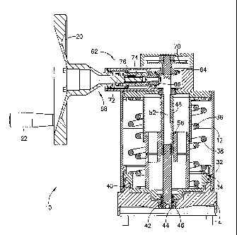
cylinders
supplied with pressurized air by a lead locomotive or engine. When the railway
vehicle is
separated from the lead locomotive, such as during the process of composing a
train, a parking
brake is desirable to prevent runaway motion of the railway vehicle.
Typically, the parking
brake is spring applied. Pushrods connected to spring-actuated pistons connect
with linkages
to effect braking function when the railway vehicle is not coupled to the lead
locomotive. The
spring-applied brakes can be released by pneumatic pressure once the vehicle
is reconnected
to a lead vehicle or a source of presSurized air,
[0004] In some prior art spring-applied brakes, a manual release is provided
for
disconnecting the piston from the pushrod, thus permitting movement of the
vehicle. In other
prior art, the application and release of the parking brake force is effected
with either air
pressure or with a mechanical winding action. In this case, the connection
between the spring-
driven piston and the pushrod is controlled by a nut threaded on the pushrod,
the rotation of
which is caused by a manual means, such as a hand wheel. This arrangement
utilizes a
conventional threaded connection between the nut and the pushrod, thereby
requiring a
significant manual input in order to actuate the manual release of the spring-
applied brake. In
certain embodiments, over 40 rotations of the hand wheel may be necessary
before the spring-
applied force is released and the railway vehicle may be moved. This process
is very inefficient
- 1 -
CA 02892912 2015-05-26
WO 2014/089264 PCT/US2013/073244
and requires a substantial amount of time and manual exertion. Additionally,
conventional
spring-applied brakes take a significant amount of time to manually apply or
release.
Accordingly, there is a need in the art for a spring-applied railway vehicle
parking brake that
overcomes the various inefficiencies of the prior art.
SUMMARY OF THE INVENTION
[0005] Briefly, according to one embodiment, there may be provided a spring-
applied
parking brake with a manual release and reapply, having a pneumatic cylinder
with a cylinder
wall and a first wall opposite a second wall. A piston may be movable within
the pneumatic
cylinder and sealed relative to the cylinder wall. At least one spring may
extend between the
piston and second wall for biasing the piston against the first wall when the
pneumatic cylinder
is depressurized. The parking brake may further include a pneumatic pressure
inlet for
applying pressure to move the piston against the spring force toward the
second wall. A hand
wheel may be provided with spindle that is operatively connected to the hand
wheel to affect
movement of a manual reset mechanism. In one embodiment, a pushrod may be
connected to
the manual reset mechanism and extend through the cylinder and the first wall.
When the hand
wheel is rotated manually, the manual reset mechanism is rotated to cause the
pushrod to move
relative to the piston corresponding to the direction of the rotation of the
hand wheel.
[0006] In accordance with another embodiment, the manual reset mechanism for
the parking
brake may include a threaded shaft having a first end slidably connected to a
first end of the
spindle and a second end connected to the pushrod and a ball screw nut
rotatably engaged with
the threaded shaft. The ball screw nut may be fixedly positioned relative to
the piston. The
threaded shaft may be hollow and include a key slot for slidably engaging a
key extending
through the spindle. The ball screw nut may be set within a sleeve connected
to the piston.
[0007] In accordance with a further embodiment, the spring-applied parking
brake may
include a pair of concentric springs. The hand wheel may be connected to a
gear box having a
first bevel gear engaging a second bevel gear. The first and second bevel
gears may have
straight or spiral teeth. In yet another embodiment, a second end of the
spindle has a toothed
ratchet releasably engaged to a release pin mechanism. The release pin
mechanism may
include a spring-loaded pullout pin that is selectively engagable with the
toothed ratchet.
Furthermore, the hand wheel may be connected to a gear box including a shaft
having a first
shaft portion selectively engagable with a second shaft portion or by
selectively engagable
gears within the gear box. The first shaft portion and the second shaft
portion may be
selectively engagable via a spring-loaded mechanism.
- 2 -
CA 02892912 2015-05-26
[0008] According to yet another embodiment, a parking brake for a railway
vehicle includes
a pneumatic cylinder having a cylinder wall and first and second walls. A
piston may be
movable within the pneumatic cylinder and sealed relative to the cylinder
wall. At least one
spring may extend between the piston and second wall for biasing the piston
against the first
wall when the pneumatic cylinder is depressurized. A pneumatic pressure inlet
may be
provided for applying pressure to move the piston against the spring force
toward the second
wall. A hand wheel may be provided with spindle that is operatively connected
to the hand
wheel to affect movement of a manual reset mechanism having a threaded shaft
with a first end
slidably connected to a first end of the spindle and a second end connected to
the pushrod and
a ball screw nut rotatably engaged with the threaded Shaft. A puShrod may be
connected to the
manual reset mechanism and extend through the cylinder and the first wall.
When the hand
wheel is rotated manually, the manual reset mechanism may be rotated to cause
the puslupd to
move relative to the piston corresponding to the direction of the rotation of
the hand wheel.
=
BRIEF DESCRIPTION OF THE DRAWINGS
[0009] Further features and other aspects and advantages will become apparent
from the
following detailed description made with reference to the drawings in which:
[0010] FIG. 1 is a perspective view of a spring-actuated parking brake in a
manually-
released state according to one embodiment;
[0011] FIG. 2 is a side view of the spring-actuated parking brake shown in
FIG. 1;
[0012] FIG. 3 is a top view of the spring-actuated parking brake shown in FIG.
1;
[0013] FIG. 4 is a cross-sectional view of the spring-actuated parking brake
shown in FIG.
1 showing a manual release pin mechanism;
[0014] FIG. 5 is a cross-sectional view of the spring-actuated parking brake
shown in FIG.
1 showing a hand wheel mechanism and a gear box;
[0015] FIG. 6 is cross-sectional view of the spring-actuated parking brake
shown in FIG.
1 in a pneumatically-released state; and
[0016] FIG. 7 is a cross-sectional view of the spring-actuated parking brake
in an applied
state.
DETAILED DESCRIPTION OF THE INVENTION
[0017] For purposes of the description hereinafter, the terms "upper",
"lower", "right",
"left", "vertical", "horizontal", "top", "bottom", "lateral", "longitudinal",
and derivatives
thereof, shall relate to the embodiment as it is oriented in the drawing
figures. However, it is
to be understood that the depicted embodiment may assume alternative
variations and step
- 3 -
CA 02892912 2015-05-26
WO 2014/089264 PCT/1JS2013/073244
sequences, except where expressly specified to the contrary. It is also to be
understood that the
specific devices and processes illustrated in the attached drawings, and
described in the
following specification, are simply exemplary embodiments. Hence, specific
dimensions and
other physical characteristics related to the embodiments disclosed herein are
not to be
considered as limiting.
[0018] Referring to the drawings in which like reference characters refer to
like parts
throughout the several views thereof, the present disclosure is generally
directed to a spring-
applied parking brake for a railway vehicle which normally is released by use
of pneumatic
pressure. With reference to FIGS. 1-3, parking brake 10 includes a cylindrical
body 12 having
a sidewall and a base portion 14 with a pneumatic connector 16 adapted for
connecting to a
pneumatic line leading from a compressed pressurized air source. Pneumatic
connector 16 is
operative for delivering air to and/or from cylindrical body 12 for effecting
a pneumatic release
of parking brake 10. Cylindrical body 12 may include a vent 18 for exhausting
air from
unpressurized portion of cylindrical body 12 during application and release of
parking
brake 10.
[0019] A hand wheel 20 is provided with a handle 22 for manually releasing or
reapplying
parking brake 10 in case a pneumatic connection is unavailable. In another
embodiment, the
hand wheel 20 may be replaced by a fixed or a removable handle. A manual
release pin
mechanism 24 having a pullout pin 26 is operatively connected to hand wheel 20
to enable
rotation of hand wheel 20 in order to manually reapply parking brake 10.
Operating principle
of parking brake 10 will be described hereafter with reference to FIGS. 4-7.
[0020] Referring now to FIGS. 4-5, cross-sectional views of parking brake 10
illustrate the
internal components of parking brake 10 with the parking brake 10 set in a
manually released
position. Cylindrical body 12 has a hollow construction having an internal
cavity 28 with base
portion 14 connected at one end and an annular wall 30 connected at the
opposing end. A
piston 32 is slidably positioned within internal cavity 28 of cylindrical body
12 and is sealed
against the sidewall of internal cavity 28 by, for example, sealing member 34
disposed in an
annular groove extending around an outer perimeter of piston 32. In one
embodiment, sealing
member 34 may be a U-shaped cup that engages the sidewall of cylinder body 12.
A pair of
concentric springs 36, 38 is positioned between annular wall 30 and piston 32
to bias piston 32
towards base portion 14. A cylinder 40 is defined between piston 32 and base
portion 14.
Cylinder 40 is in fluid communication with pneumatic connector 16 for
introducing pressurized
air into cylinder 40 and driving piston 32 toward annular wall 30 in order to
disengage parking
brake 10. Pressurizing cylinder 40 with compressed air delivered though
pneumatic connector
- 4 -
CA 02892912 2015-05-26
WO 2014/089264 PCT/US2013/073244
16 causes piston 32 to move toward annular wall 30 against the pressure
exerted by concentric
springs 36, 38. Such movement of piston 32 within cylinder 40 effects a
pneumatic release of
parking brake 10. Should the air pressure be removed, springs 36, 38 will
drive piston 32 back
toward base portion 14.
[0021] A pushrod 42 is centrally positioned within cylinder 40 and is axially
movable
relative to base portion 14 and cylinder 40. In a position where parking brake
is engaged, such
as illustrated in FIG. 7, first end of pushrod 42 extends through a central
opening 44 in base
portion 14. Pushrod 42 is sealed at the interface with base portion 14 and
cylinder 40 by one
or more sealing members 46. In one embodiment, the one or more sealing members
46 may
be a U-shaped cup adapted for engaging the sidewall of cylinder body 12.
[0022] With continuing reference to FIGS. 4-5, pushrod 42 is connected at its
second end to
a lower portion of a threaded shaft 48 of a ball screw reset mechanism 50
adapted for manually
releasing and reapplying parking brake 10. Threaded shaft 48 is operatively
connected to
spindle 52 such that rotation of spindle 52 causes a corresponding rotation of
threaded shaft
48. A helical thread extends around the exterior of threaded shaft 48. A
hollow interior portion
of threaded shaft 48 includes a key slot (not shown) extending throughout the
length of threaded
shaft 48. The key slot is adapted for receiving a key 54 extending through a
lower portion of
spindle 52. This structural arrangement permits threaded shaft 48 to slide
axially with respect
to the lower end of spindle 52 while allowing threaded shaft 48 to rotate with
the rotation of
spindle 52. Threaded shaft 48 engages a ball screw nut 56 that is fixed to a
cylindrical sleeve
58 disposed around the collar. Cylindrical sleeve 58,is connected to an upper
face of piston 32
such that axial movement of piston 32 causes a corresponding movement of
cylindrical sleeve
58. In one embodiment, ball screw nut 56 is fixed to cylindrical sleeve 58 by
a set screw 60.
Because ball screw nut 56 is in a fixed relationship with cylindrical sleeve
58, rotation of
spindle 52 causes a corresponding rotation of threaded shaft 48, which in turn
causes threaded
shaft 48 to move relative to ball screw nut 56. Operation of parking brake 10
to effect manual
release and reapplication of the braking force will be described in greater
detail hereafter.
[0023] With reference to FIG. 5, upper portion of spindle 52 extends through
annular wall
30 and is engaged with a gear box 62. Gear box 62 provides for application of
the winding
action perpendicular to spindle 52 to be next described. As shown in FIG. 5, a
first bevel gear
64 is provided on spindle 52 and a second bevel gear 66 is provided on a shaft
68 of hand wheel
20 such that rotation of hand wheel 20 causes a corresponding rotation of
spindle 52 through
the engagement of first bevel gear 64 and second bevel gear 66. In one
embodiment, first and
second bevel gears may have straight or spiral teeth. Gear box 62 allows for
higher or lower
- 5 -
CA 02892912 2015-05-26
WO 2014/089264 PCT/US2013/073244
winding speed and torque based on the ratio of the gear box. The first and
second bevel gears
may be selected to have a desired gear ratio to achieve a desired force input
that is required to
manually release parking brake 10. For example, in one embodiment, the first
and second
bevel gears may have a 2:1 ratio such that two full rotations of second bevel
gear 66 cause one
rotation of first bevel hear 64. One of ordinary skill in the art will
appreciate that any desired
gear ratio between the first and second bevel gears may be selected. In
another embodiment,
the hand wheel 20 is directly connected to the spindle 52 without the use of
the gear box 62.
In yet another embodiment, the gear box 62 may include spur-type gears such
that the hand
wheel 20 is parallel and radially offset relative to the spindle 52.
[0024] With reference to FIG. 4, top portion of spindle 52 has a toothed
ratchet 70 that is
selectively engagable with manual release pin mechanism 24. Pullout pin 26 is
spring loaded
by a first spring 78 and may be axially moved within a predetermined range of
motion to engage
to and from ratchet 70. Pullout pin 26 includes a first portion 27 and a
second portion 29. In
a default position, second portion 27 of pullout pin 26 is urged by a second
spring 80 to engage
ratchet 70 and prevent manual rotation of spindle 52. By manually withdrawing
first portion
27 of pullout pin 26 fiom the default position, first spring 78 is compressed
and second portion
29 of pulllout pin 26 is disengaged from ratchet 70, thereby allowing spindle
52 to rotate freely.
[00251 Referring to FIG. 5, shaft 68 includes a first shaft portion 72 that is
releasably
coupled to second shaft portion 74. A spring-loaded mechanism 76 biases second
shaft portion
74 away from first shaft portion 72 in a default state when hand wheel 20 is
not utilized, such
as during manual release of the brakes, a pneumatic reapplication, or normal
pneumatic
operation. To affect engagement of second shaft portion 74 with first shaft
portion 72, the
force of spring-loaded mechanism 76 is overcome by axially pushing second
shaft portion 74
toward first shaft portion 72 and turning second shaft portion 74 with respect
to first shaft
portion 72 until a pin on second shaft portion 74 engages a slot on first
shaft portion 72. In
another embodiment, the gear box 62 may be connected to the hand wheel 20 by
selectively
engagable gears within the gear box 62. For example, at least one of the
selectively engagable
gears may be mounted on a slidable shaft that is spring-loaded to affect the
selective
engagement with the other gear(s).
[0026] FIG. 7 shows parking brake 10 in an applied state, wherein piston 32 is
located
proximate to base portion 14 such that air is exhausted from cylinder 40.
Because there is no
air pressure acting on the piston face, concentric springs 36, 38 maintain
piston 32 against base
portion 14. While FIG. 7 illustrates the piston 32 abutting the surface of the
base portion 14,
a slight gap may exist therebetween such that the force of the concentric
springs 36, 38 is
- 6 -
CA 02892912 2015-05-26
WO 2014/089264 PCT/US2013/073244
transferred to the spindle 52. In the applied position, pushrod 42 applies a
braking force via a
linkage (not shown) to the service brake mechanism (not shown). In order to
release parking
brake 10, pressurized air may be introduced into cylinder 40 via pneumatic
connector 16 to
cause piston 32 to act against the force provided by concentric springs 36,
38. With reference
to FIG. 6, piston 32 is moved upward as cylinder 40 is filled with compressed
air, causing
springs 36, 38 to be compressed. Upward motion of piston 32 withdraws pushrod
42 into
cylinder 40 to disengage parking brake 10.
[0027] Once parking brake 10 has been set by the action of springs 36, 38 and
pneumatic
pressure is no longer available, such as when the railway vehicle is decoupled
from the lead
locomotive having a pressurized air source, parking brake 10 cannot be
pneumatically released
and must be released manually. In order to manually release parking brake 10,
pullout pin 26
is disengaged from ratchet 70 to allow spindle 52 to rotate freely. Reaction
force of the service
brake against pushrod 42 to be driven into the retracted position. Upward
movement of pushrod
42 causes threaded shaft 48 to rotate as it moves through ball screw nut 56,
which consequently
rotates spindle 52. In order to manually reapply parking brake 10, such as,
for example, after
rearranging the position of the railway vehicle in a railway yard, pullout pin
26 is returned to
its default position where it engages ratchet 70. The user engages hand wheel
20 in order to
manually force pushrod 42 into an extended position wherein it activates the
brakes of the
railway vehicle. Rotation of hand wheel 20 and shaft 68 is affected by axially
pushing and
rotating second shaft portion 74 toward first shaft portion 72 against the
restoring force
provided by spring-loaded mechanism 76 until the pin on second shaft portion
74 engages a
corresponding slot on first shaft portion 72. Rotation of hand wheel 20 causes
a corresponding
rotation of shaft 68, which in turn rotates first bevel gear 64. As first
bevel gear 64 is rotated,
it engages second bevel gear 66 to cause a corresponding rotation of spindle
52. Rotation of
spindle 52 causes a corresponding rotation of threaded shaft 48 when key 54
extending though
spindle 52 engages a corresponding slot on threaded shaft 48. As threaded
shaft 48 is rotated,
it is advanced in an downward direction through ball screw nut 56. Because the
lower end of
threaded shaft 48 is connected to pushrod 42, downward movement of threaded
shaft 48 also
causes pushrod 42 to move downward, thereby engaging parking brake 10.
[0028] The parking brake 10 incorporating the ball screw reset mechanism 50
described
above greatly improves the efficiency of manually reapplying the brake
compared to existing
methods and devices. Because of the inherent efficiency of ball screw design
over conventional
threads, the ball screw reset mechanism 50 significantly reduces the effort
necessary to affect
rotation of hand wheel 20, thereby allowing for easier operation.
Additionally, the increased
- 7 -
CA 02892912 2016-01-07
= .-
. .
efficiency allows for the use of a higher gear reduction to reduce the number
of turns of hand
wheel 20 to reset parking brake 10.
[0029] Although the present invention has been described with reference to its
preferred
embodiments, it will be understood that the scope of the claims should not be
limited by
the preferred embodiments, but should be given the broadest interpretation
consistent
with the description as a whole.
=
- 8 -