Note: Descriptions are shown in the official language in which they were submitted.
CA 02892964 2015-05-26
H8323753CA
- 1 -
Dual clutch comprising two clutch units which act in a force-fitting manner
The invention relates to a dual clutch comprising two clutch units, which act
nonpositively and which are mounted on a common clutch hub for conjoint
rotation and in an axially movable manner - in relation to an axis of clutch
__ rotation - comprising a multipart pressure disk arrangement, which is held
in an axially fixed manner on the clutch hub between the clutch units, and
comprising two axially movable pressure pistons, each of which can be
released by means of a compression spring arrangement positioned in the
clutch hub, wherein each aperture is introduced into the clutch hub as an
__ axially extending blind hole.
A dual clutch of this kind is known from Catalog No. D 228, dated 01.1999,
published by Stromag AG. The known dual clutch has two plate packs,
which are mounted for conjoint rotation and axial movement on a common
clutch hub. The two plate packs are separated from one another by a
__ pressure disk arrangement, which is seated externally on the clutch hub
and is secured axially on the clutch hub. The two plate packs can each be
acted upon by an axially movable pressure piston, which can each be
transferred into a release position for the plate packs by means of a
compression spring arrangement positioned in the clutch hub.
__ DE 10 2010 046 633 Al discloses another dual clutch, in which a pressure
disk arrangement is arranged axially between two plate packs. The
pressure disk arrangement is accommodated in an outwardly open radial
groove in the clutch hub. Corresponding compression springs of the
compression spring arrangements for releasing the pressure pistons are
__ supported on the pressure disk arrangement. The corresponding apertures
of oppositely situated compression springs in the clutch hub are aligned
coaxially with one another and are each formed by a common hole, which
passes through the entire length of the clutch hub. The pressure disk
arrangement is constructed from three parts, comprising two pressure disk
__ segments, which adjoin one another in the circumferential direction, and a
carrier ring, to which the pressure disk segments are axially connected.
It is an object of the invention to provide a dual clutch of the type stated
at
the outset which allows disassembly and reassembly.
=
CA 02892964 2015-05-26
H8323753CA
- 2 -
This object is achieved by virtue of the fact that the pressure disk
arrangement is accommodated in a radial groove in the clutch hub, said
groove being spaced apart radially and/or axially from the blind holes in
relation to the axis of clutch rotation. Accommodating the pressure disk
arrangement in the radial groove ensures reliable fixing of the pressure disk
arrangement on the clutch hub. By virtue of the fact that the radial groove is
spaced apart radially and/or axially from the blind holes, the pressure disk
arrangement can be assembled and disassembled without being affected
by the position and functioning of the pressure disk arrangements. In DE
10 2010 046 633 Al, removal of the pressure disk arrangement after
successful initial installation was virtually impossible since at least one
compression spring arrangement is supported axially on the pressure disk
arrangement and makes removal of the pressure disk arrangement
impossible or possible only under more difficult conditions, owing to the
high spring stress.
In a refinement of the invention, the pressure disk arrangement has at least
two pressure disk segments, which adjoin one another in the
circumferential direction, and a one-part carrier ring, to which the pressure
disk segments are connected. Each pressure disk segment
advantageously has an axially extending shoulder situated radially on the
inside, which is adjoined radially on the outside by the carrier ring. In this
arrangement, an axial extent of the shoulder preferably corresponds to an
axial thickness of the carrier ring. In order to ensure exclusive frictional
contact by the carrier ring, the carrier ring is preferably always slightly
thicker than the axial extent of the shoulder. A radial distance of the
shoulder from a radially outer boundary edge of the respective pressure
disk segment advantageously corresponds to a radial extent of the carrier
ring. By means of the refinements described, a contact surface on a flat
part of the pressure disk arrangement is achieved for the clutch units,
resulting in a particularly uniform surface pressure for the corresponding
clutch units. In a further refinement, the radial extent of the carrier ring
corresponds at least largely to a radial extent of an effective contact
surface of the adjacent clutch unit. A plate pack comprising a plurality of
inner and outer plates is preferably provided as a clutch unit. Both the
carrier ring opposite the adjacent clutch unit and a face, facing the other
clutch unit, of the at least two pressure disk segments form correspondingly
flat contact surfaces extending radially in a continuous one-piece way. By
CA 02892964 2015-05-26
H8323753CA
- 3 -
virtue of the refinements, the carrier ring furthermore rests in an accurately
fitting manner, with support radially on the inside, on the pressure disk
segments, with the result that outer surfaces of the carrier ring end flush
and in alignment with corresponding outer contours of the pressure disk
segments. As a result, the pressure disk segments and the carrier ring rest
against one another in a particularly compact way and in the form of a
pack, ensuring that at most slight elastic deformations occur between the
carrier ring and the pressure disk segments during clutch operation. These
measures too result in particularly uniform surface pressure of the pressure
disk arrangement relative to the adjacent clutch units, in particular plate
packs. By virtue of the refinements described, the pressure disk segments
and the carrier ring rest flat upon one another in such a way that power flow
always takes place via the wide contact surfaces between the pressure
disk segments and the carrier ring during clutch operation, even in the case
of elastic deformations.
In a further refinement of the invention, the at least two pressure disk
segments are each held spaced apart at the joints thereof as seen in the
circumferential direction by a key, each of which keys is fitted into a
complementary key slot in a base of the radial groove. This allows
improved suitability of the pressure disk arrangement for fitting on the
clutch hub.
By means of the solution according to the invention, it is possible to enable
disassembly of the dual clutch from one axial side and, accordingly,
replacement of the corresponding clutch units, in particular plate packs.
The dual clutch according to the invention is advantageously provided for
use in an industrial transmission, preferably for driving an exploration pump
for delivering crude oil. As an alternative, the invention can also be used
with machine tools, in industrial plant or on commercial vehicles.
Further advantages and features of the invention will become apparent
from the claims and from the following description of a preferred exemplary
embodiment of the invention, which is illustrated by means of the drawings,
in which:
Figure 1 shows one embodiment of a dual clutch according to the invention
in a front view,
CA 02892964 2015-05-26
H8323753cA
- 4 -
Figure 2a shows a longitudinal section through the dual clutch along
section line a-a in figure 1,
Figure 2b shows a longitudinal section through the dual clutch according to
figure 1 along section line b-b,
Figure 3 shows a multipart pressure disk arrangement of the dual clutch
according to figures 1 to 2b in an enlarged front view,
Figure 4 shows a section through the pressure disk arrangement along
section line IV-IV in figure 3, and
Figure 5 shows another section through the pressure disk arrangement
according to figure 3 along section line V-V in figure 3
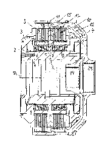
A hydraulic dual clutch according to figures 1 to 5 has a single-part inner
body 1 serving as a clutch hub in the sense according to the invention. A
first pressure piston 3 is supported in an axially movable manner on the
inner body 1 on the left-hand side, and a second pressure piston 4 is
supported in an axially movable manner on said inner body on the right-
hand side - relative to the drawings according to figures 2a and 2b. The two
pressure pistons 3 and 4 can be subjected to hydraulic pressure in
opposite directions to one another. For this purpose, a cylinder wall 2 is
provided for the first pressure piston 3 on the left-hand side, and a second
cylinder wall is provided for the pressure piston 4 on the right-hand side.
Two clutch units in the form of two plate packs 9, 10, each consisting of a
plurality of inner and outer plates, are arranged between the axially spaced
pressure pistons 3. The inner plates of the two plate packs 9, 10 are held
for conjoint rotation and axial movement by means of longitudinal splines
extending axially with respect to an axis of clutch rotation D. The outer
plates of the two plate packs 9, 10 are connected for conjoint rotation and
axial movement, by means of corresponding external splines, to axially
extending internal splines on two clutch bells 11, 12, wherein the clutch bell
11 associated with the left-hand plate pack 9 defines a first output 13, and
the clutch bell 12 associated with the second plate pack 10 defines an
output 14, which is aligned coaxially with the first output 13.
CA 02892964 2015-05-26
H8323753CA
- 5 -
The two plate packs 9, 10 are separated axially from one another by a
pressure disk arrangement 15, which is of ring-shaped configuration and is
embedded in a radial groove R in the inner body 1, said groove being
arranged in an axially central manner. The radial groove R is made deeper
than corresponding axial groove depths of the axially extending plate
splines on the inner body 1, as is readily apparent from figures 2a and 2b.
A compression spring arrangement 5, 6; 7, 8 for each pressure piston 3, 4
is furthermore integrated into the inner body 1, said arrangement
comprising a plurality of compression springs 6, 8 arranged in a manner
distributed over the circumference of the inner body 1. The compression
springs 6, 8 are of identical configuration to one another and are embodied
as helical compression springs. Each compression spring 6, 8 is integrated
into an associated aperture 5, 7 in the inner body 1. The apertures 5, 7 are
introduced as blind holes into the inner body 1, from opposite ends of the
latter, and extend parallel to the axis of rotation D of the dual clutch.
Accordingly, each compression spring 6, 8 is supported axially on the
inside against a base of the associated aperture 5, 7 configured as a blind
hole and exerts a pressure force on the corresponding pressure piston 3, 4
in the direction of release, in which the respective pressure piston 3, 4 is
pushed axially away from the associated plate pack 9, 10. The radial
groove R and the apertures 5, 7 do not merge into one another; on the
contrary, they are separated from one another axially and radially, thus
ensuring that the radial groove R is completely closed over its entire
periphery, radially toward the inside and toward both axial sides.
The pressure disk arrangement 15 has a carrier ring 17, which is a single
continuous part over its entire circumference and is connected to two semi-
annular pressure disk segments 16a, 16b. Each semicircular pressure disk
segment 16a, 16b has an axially projecting shoulder 18 in the form of a
circular arc, which is provided radially on the inside of the respective
pressure disk segment 16b. An axial extent of the shoulder 18 corresponds
approximately to an axial thickness of the carrier ring 17. At the same time,
it must be ensured that the axial thickness of the carrier ring 17 is always
slightly greater than the greatest axial extent of the shoulder 18. This
ensures that the flat outer surface of the carrier ring 17 always forms a
corresponding friction surface for the adjacent plate pack 10 and that an
end face of the shoulder 18 does not come into contact with the facing
CA 02892964 2015-05-26
H8323753CA
- 6 -
friction surface of the plate pack 10. A radial extent, from the radial outer
side of the shoulder 18 to the radially outer boundary edge of each
pressure disk segment 16a, 16b, is identical with the radial extent of the
carrier ring 17, thus ensuring that, as illustrated in figures 4 and 5, the
carrier ring 17 lies flat and flush against a facing face of the respective
pressure disk segment 16a, 16b by means of one face and otherwise ends
flush and in alignment with the outer surfaces of the respective pressure
disk segment 16a, 16b by means of its outer contour, both in the region of
the shoulders 18 and in the radially outer rim region.
A key P is inserted radially on the inside at each of the two joints between
the adjoining pressure disk segments 16a, 16b, said keys being assigned a
corresponding key slot N in the radially inner base of the radial groove R in
the inner body 1. During assembly of the pressure disk arrangement 15,
the two keys P are inserted into the key slots N before the pressure disk
segments 16a and 16b are placed on the inner body 1 radially from the
outside and inserted radially into the radial groove R. The keys P make it
easier to position the pressure disk segments 16a, 16b within the radial
groove R. After the insertion of the pressure disk segments 16a, 16b, the
carrier ring 17 is pushed axially over the inner body 1 and centered on the
circular-arc-shaped shoulders 18 of the pressure disk segments 16a, 16b.
The carrier ring 17 is then fixed on the pressure disk segments 16a, 16b by
means of axially acting fastening means in the form of screw fasteners 19.
For this purpose, the pressure disk segments 16a, 16b have threaded
holes, and corresponding sockets for corresponding headed screws, which
are screwed into the threaded holes, are provided in the carrier ring 17.
In the dual clutch illustrated by means of figures 1 to 5, the plate packs 9,
10 can be replaced in a simple manner from one side of the clutch. This is
the right-hand side of the clutch in the illustration according to figures 2a
and 2b. After the two clutch bells 11 and 12 have been pulled off axially,
the cylinder wall associated with pressure piston 4 is removed. After
pressure piston 4 has been pulled off axially, plate pack 10 is removed
axially. The carrier ring 17 of the pressure disk arrangement 15 is then
screwed off the remaining pressure disk segment and removed axially to
the right. The pressure disk segments 16a, 16b can then be pulled radially
outward out of the radial groove R in the inner body 1. The first plate pack 9
is thus also exposed and can be removed axially from the inner body 1 via
CA 02892964 2015-05-26
H8323753CA
- 7 -
the right-hand side of the clutch. By means of correspondingly reversed
assembly operations, a new plate pack 9, the pressure disk arrangement
15 and, if appropriate, another new plate pack 10 can then be installed
again before pressure piston 4, the associated cylinder wall and the two
clutch bells 11 and 12 are placed on again axially and fitted ready for
operation.
The positioning of the keys P within the radial groove R for conjoint rotation
in the circumferential direction ensures support for conjoint rotation for the
pressure disk segments 16a, 16b and, consequently, secure driving in
rotation together with the inner body 1. As is readily apparent from figures
2a and 2b, a radial extent of the carrier ring 17 corresponds approximately
to a radial extent of an effective contact surface of the adjacent inner plate
of plate pack 10, wherein, radially on the outside, the carrier ring 17 also
ends at least substantially in alignment with an outer rim of the
corresponding inner plate. As a result, a contact surface which is flat
throughout is obtained between the facing face of the carrier ring 17 and
the contact surface, facing the carrier ring 17, of the adjacent inner plate
of
plate pack 10, thereby making it possible to achieve a particularly good
surface pressure. Since the opposite faces of the pressure disk segments
16a, 16b, which face the other plate pack 9, also form a flat surface over
their entire radial extent, a particularly uniform surface pressure is
obtained
on the side facing the other plate pack 9.