Note: Descriptions are shown in the official language in which they were submitted.
CA 02893081 2015-05-29
WO 2014/105043 PCT/US2012/071996
1
SYSTEM AND METHOD FOR MANAGING PRESSURE WHEN DRILLING
TECHNICAL FIELD
The present disclosure generally relates to oilfield drilling equipment and,
in
particular, to an apparatus and method for managing pressure when drilling.
BACKGROUND
Conventional offshore drilling techniques control pressure inside the wellbore
by utilizing the hydrostatic pressure generated by drilling fluid circulated
through the
well. When using only hydrostatic pressure to control wellbore pressure, it
can be
difficult to compensate for pressure changes because pressure in the wellbore
may be
adjusted only by changing the density or specific gravity of the drilling
fluid, or by
adjusting the mud pump circulation rate. But these methods are incapable of
addressing sudden unexpected changes in pressure, as circulation rate induced
pressure changes are small, and it can take hours to change the makeup of the
drilling
fluid. Newer techniques, such as underbalanced drilling and managed pressure
drilling, address this problem by closing the annulus and utilizing pressure
management devices to control wellbore pressure.
BRIEF DESCRIPTION OF THE DRAWINGS
Some specific exemplary embodiments of the disclosure may be understood
by referring, in part, to the following description and the accompanying
drawings.
FIGURE 1 is a schematic diagram of an offshore drilling fluid return system
including a pressure management device, in accordance with one embodiment of
the
present disclosure.
FIGURE 2 is a schematic diagram of an offshore drilling fluid return system
including a pressure management device, in accordance with another embodiment
of
the present disclosure.
FIGURE 3 is a schematic diagram of an offshore drilling fluid return system
including a pressure management device, in accordance with another embodiment
of
the present disclosure.
FIGURE 4 is a schematic diagram of an offshore drilling fluid return system
including a pressure management device, in accordance with another embodiment
of
the present disclosure.
1
CA 02893081 2015-05-29
WO 2014/105043 PCT/US2012/071996
2
FIGURE 5 is a flowchart of an example method of managing pressure in a
drilling system, in accordance with the present disclosure.
While embodiments of this disclosure have been depicted and described and
are defined by reference to exemplary embodiments of the disclosure, such
references
do not imply a limitation on the disclosure, and no such limitation is to be
inferred.
The subject matter disclosed is capable of considerable modification,
alteration, and
equivalents in form and function, as will occur to those skilled in the
pertinent art and
having the benefit of this disclosure. The depicted and described embodiments
of this
disclosure are examples only, and not exhaustive of the scope of the
disclosure.
DETAILED DESCRIPTION
The present disclosure relates generally to well drilling operations and, more
particularly, to systems and methods for managing pressure while drilling by
using a
pressure management device, as described herein. Pressure management devices,
also
known or variously termed as rotating control devices, rotating control heads,
pressure control heads, rotating drilling device, rotating drilling head,
rotating annular
and other similar terms, may contain a primary bearing package and a sealing
package, which permit the pressure management device to seal around a rotating
drill
pipe and maintain pressure in the annulus (the area between the outside of the
drill
pipe and the inside of the riser and/or casing and/or open hole). If and when
the
primary bearing package malfunctions and/or the sealing package begins to
leak, it
may be necessary to remove all or part of the pressure management device in
order to
repair and/or replace either the primary bearing package or the sealing
package.
The systems and methods of this disclosure may be utilized to avoid the time
consuming removal of thc pressure management device during drilling
operations.
FIGURE 1 illustrates an offshore drilling fluid return system 100 including a
pressure
management device 140. System 100 may include a drill pipe 110, a rotary table
120,
a diverter assembly 130, a pressure management device 140, a quick release
clamp
170, and a receiver or tie back mandrel 180. Drill pipe 110 may be part of a
drill
string associated with a drill bit that may be used to form a wide variety of
wellbores
or bore holes. The drill string may include additional components including,
but not
limited to, drill bits, drill collars, rotary steering tools, directional
drilling tools,
downhole drilling motors, reamers, hole enlargers, or stabilizers. Drill pipe
110 may
CA 02893081 2015-05-29
WO 2014/105043 PCT/US2012/071996
3
be coupled to rotary table 120 and rotate with the rotary table 120, such that
the rotary
table 120 may be used to drive drill pipe 110 and the other components of the
drill
string. Alternatively, drill pipe 110 may be coupled to a top drive or other
system
similarly used to rotate the drill pipe 110.
Pressure management device 140 may include a housing 150, a primary
bearing package 160, and a removable sealing package 190. Pressure management
device 140 may be configured to control the pressure inside the wellbore
and/or riser
by preventing the circulation of drilling fluid uphole of pressure management
device
140. Thus, instead of circulating drill fluid returns uphole of pressure
management
device and exiting the system through diverter assembly or bell nipple 130,
the
drilling fluid returns may be circulated through a choke valve, which may
increase or
decrease the pressure of the drilling fluid, and thus the pressure exerted on
the
wellbore. At its downhole end, housing 150 may be coupled via a flange or
quick
release clamp 170 to a riser pipe or a component of a riser assembly. At its
uphole
end, housing 150 may be coupled via a companion flange, clamp or other similar
mating device to receiver or tie back mandrel 180 to a riser pipe or a
component of a
riser assembly.
Primary bearing package 160 may be coupled to housing 150 in a manner that
prevents drilling fluid from flowing between housing 150 and primary bearing
package 160. Primary bearing package 160 may include a bearing assembly 162,
inner sleeve 164, and seals 166. To permit the removal of drill pipe 110
and/or other
components of the drill string without removing primary bearing package 160,
the
inner diameter of inner sleeve 164 may be sized such that drill pipe 110 and
drill
string components can pass freely through inner sleeve 164.
Bearing assembly 162 may be configured to permit inner sleeve 164 to rotate
with respect to housing 150. Bearing assembly 162 may be any type of bearing
capable of supporting rotational and thrust loads. For example, bearing
assembly 162
may include roller bearings, ball bearings, journal bearings, tilt-pad
bearings, and/or
diamond bearings. Seals 166 may isolate bearing assembly 162 from the drilling
fluids circulating in the annulus. Seals 166 may be o-ring or other rotating
type seals
located along the uphole and downhole circumference of bearing assembly 162.
Seals
166 may be rubber, nitrile, urethane, or any other similar elastomeric
material.
CA 02893081 2015-05-29
WO 2014/105043 PCT/US2012/071996
4
Removable sealing package 190 may include a housing 192, latching elements
194, seal elements 196, and seals 198. Removable sealing package 190 may be
configured to seal the annulus and thus substantially prevent the circulation
of drilling
fluid uphole of pressure management device 140. Removable sealing package 190
may encompass drill pipe 110 such that at least a portion of housing 192 is
adjacent
inner sleeve 164. Vertical movement of removable sealing package 190 may be
prevented by latching elements 194, which may extend radially from housing 192
to
engage a latching indentation, formation, or shoulder on inner sleeve 164.
Latching
element 194 also centers the removable sealing package 190 with respect to the
inner
sleeve 164. When latching elements 194 are engaged, rotation of drill pipe 110
may
induce rotation of removable sealing package 190 and primary bearing package
160.
Latching elements 194 may be hydraulically, pneumatically, mechanically, or
electrically actuated such that removable sealing package 190 may be easily
engaged
and disengaged from primary bearing package 160.
Seal elements 196 may be cone-shaped elements configured to encompass
drill pipe 110 and automatically seal between drill pipe 110 and housing 192
when a
drill pipe 110 is inserted through housing 150. Removable sealing package 190
may
contain two seal elements 196, one uphole from the other. Removable sealing
package 190 may, however, function with a single seal element 196 installed at
either
end of removable sealing package 190. Seal 198 may be an o-ring type seal
located
along the circumference of housing 192 and configured to seal between housing
192
and inner sleeve 164. Seal elements 196 and seal 198 may be rubber, nitrile,
urethane, or any other similar elastomeric material.
Removable sealing package 190 may have a limited operable life (e.g., 100-
200 drilling hours) before it begins to leak or otherwise malfunction. In the
event of a
leak and/or malfunction, removable sealing package 190 may be removed from
pressure management device 140 by actuating latching elements 194 such that
they no
longer engage the latching indentation, formation, or shoulder on inner sleeve
164.
Once disengaged, removable sealing package 190 may be removed from the
wellbore
and replaced with an operable sealing package. FIGURE 2 illustrates a pressure
management device in which sealing package 190 has been removed.
Removable sealing package 190 may also be removed from the wellbore if
CA 02893081 2015-05-29
WO 2014/105043 PCT/US2012/071996
primary bearing package 160 fails. If primary bearing package 160 fails,
removable
sealing package 190 may be removed from the wellbore and a secondary bearing
package 310 (shown in FIGURES 3 and 4) may be installed uphole from and
adjacent
to primary bearing package 160. Secondary bearing package 310 may be installed
5 without
removing primary bearing package 160 and/or pressure management device
140. Following the failure of primary bearing package 160, secondary bearing
package 310 and removable sealing package 190 may be installed as a single
unit
(e.g., secondary bearing package 310 may be installed with removable sealing
package 190 already engaged) or they may be installed separately.
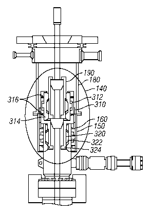
FIGURE 3 illustrates an offshore drilling fluid return system 300 in which a
secondary bearing package 310 has been installed separeately from a removable
sealing package 190. As shown in FIGURE 3, secondary bearing package 310 may
be installed uphole from primary bearing package 160 without removing primary
bearing package 160. Secondary bearing package 310 may include a bearing
assembly 312, an inner sleeve 314, seals 316, and engagement assembly 320,
which
may include latching elements 322 and seal 324.
Bearing assembly 312 may be configured to permit inner sleeve 314 to rotate
with respect to housing 150. Bearing assembly 312 may be any type of bearing
capable of supporting rotational and thrust loads. For example, bearing
assembly 312
may include roller bearings, ball bearings, journal bearings, tilt-pad
bearings, and/or
diamond bearings. Seals 316 may isolate bearing assembly 312 from the drilling
fluids circulating in the annulus. Seals 316 may be o-ring type seals located
along the
uphole and downhole circumference of bearing assembly 312. Seals 316 may be
rubber, nitrite, urcthanc, or any other similar elastomeric material.
Engagement assembly 320 may be configured to extend into primary bearing
package 160, as shown in FIGURE 3. Latching elements 322 may extend radially
from engagement assembly 320 to engage the latching indentation, formation, or
shoulder on inner sleeve 164 of primary bearing package 164. Like latching
elements
194 of removable sealing package 190, latching elements 322 may be
hydraulically,
pneumatically, mechanically, or electrically actuated such that secondary
bearing
package 310 may be easily engaged with primary bearing package 160. Seal 324
may
be an o-ring type seal located along the circumference of engagement assembly
320
CA 02893081 2015-05-29
WO 2014/105043 PCTTUS2012/071996
6
and configured to provide a seal between engagement assembly 320 of secondary
bearing package 310 and inner sleeve 164 of primary bearing package 160. Seal
324
may be rubber, nitrile, urethane, or any other similar elastomeric material.
Although FIGURES 1-3 illustrate only a primary bearing package 160 and a
secondary bearing package 310, additional bearing packages may be installed
provided that housing 150 has sufficient space. For example, a tertiary
bearing
package may be installed uphole from secondary bearing package 310 without
removing primary bearing package 160 or secondary bearing package 310.
Additional bearing packages may be stacked in this manner so long as there is
space
in housing 150.
As discussed above, FIGURE 4 illustrates a removable sealing package 190
engaged with secondary bearing package 310. As discussed above, secondary
bearing
package 310 and removable sealing package 190 may be installed as a single
unit or
they may be installed separately. When removable sealing package 190 is
engaged
with secondary bearing package 310, vertical movement of removable sealing
package 190 may be prevented by latching elements 194, which may extend
radially
from housing 192 to engage a latching indentation, formation, or shoulder on
inner
sleeve 314 of secondary bearing package 310. When latching elements 194 are
engaged, rotation of drill pipe 110 may induce rotation of removable sealing
package
190 and secondary bearing package 310. When removable sealing package 190 is
installed in conjunction with secondary bearing package 310, downhole seal
element
196 may seal with the surface of engagement assembly 320, thereby
substantially
preventing circulation of drilling fluids uphole from pressure management
device 140.
FIGURE 5 illustrates an example method 500 of managing pressure in a
drilling system using a pressure management device in accordance with the
present
disclosure. At 505, primary bearing package may be positioned within and
coupled to
the housing of the pressure management device. At step 510, primary bearing
package may be sealed to the housing of the pressure management device. At
step
515, the downhole end of the housing of the pressure management device may be
coupled via a flange or quick connect clamp to a riser or a component of a
riser
assembly.
At step 520, the primary bearing package may be sealed to the drill pipe. As
CA 02893081 2015-05-29
WO 2014/105043 PCT/US2012/071996
7
discussed above, the primary bearing package may be sealed to the drill pipe
via a
removable sealing package, which may engage with the primary bearing package
to
seal the annulus, thereby substantially preventing the circulation of drilling
fluid
returns uphole of the pressure management device. At step 525, a determination
may
be made as to whether the primary bearing package is sealing. If the primary
bearing
package is operational, the method may proceed to step 530.
At step 530, a determination may be made regarding whether the removable
sealing package is maintaining a seal between the primary bearing package and
the
drill pipe. If so, the method may proceed to step 535. If it is determined
that the
removable sealing package is not maintaining a seal between the primary
bearing
package and the drill pipe, the method may proceed to step 540. At step 540,
the
removable sealing package may be removed from the pressure management device
and replaced. Following replacement of the removable sealing package, the
method
may again proceed to step 530. If the replacement sealing package is sealing,
the
method may proceed to step 535. At step 535, the drilling system may be
operated
and the pressure in the wellbore may be managed using the pressure management
device.
If, at step 525, it is determined that the primary bearing package has become
non-operational, the method may proceed to step 545. At step 545, an
additional
bearing package may be positioned uphole from the primary bearing package
within
the housing of the pressure management device. As discussed above, if the
primary
bearing package fails, the removable sealing package may be removed from the
wellbore and an additional bearing package may be installed uphole from and
adjacent to the primary bearing package. The additional bearing package may
engage
the primary bearing package via an engagement assembly, thereby substantially
preventing vertical movement of the additional bearing package.
At step 550, the additional bearing package may be sealed to the primary
bearing package or the housing of the pressure management device. The
additional
bearing package may be sealed to the primary bearing package using an o-ring
type
seal located along the circumference of the engagement assembly of the
additional
bearing package and configured to provide a seal between the engagement
assembly
of the secondary bearing package and an inner sleeve of the primary bearing
package.
CA 02893081 2015-05-29
WO 2014/105043 PCT/US2012/071996
8
Alternatively, or additionally, an additional bearing package may include an o-
ring
type seal located along its uphole circumference, which may be configured to
provide
a seal between the additional bearing package and the housing of the pressure
management device.
At step 555, the additional bearing package may be sealed to the drill pipe.
The additional bearing package may be sealed to the drill pipe via a removable
sealing
package. The removable sealing package may be installed in conjunction with
the
additional bearing package or may be installed separately. When the removable
sealing package is engaged with the additional bearing package, a downhole
seal
element may seal with the surface of the engagement assembly of the additional
bearing package, thereby substantially preventing circulation of drilling
fluid returns
uphole from the pressure management device.
Following the installation and sealing of the additional bearing package, the
method may proceed to step 530, where a determination may be made regarding
whether the removable sealing package is maintaining a seal between the
bearing
package and the drill pipe. If the removable sealing package is sealing, the
method
may proceed to step 535. At step 535, the drilling system may be operated and
the
pressure in the wellbore may be managed using the pressure management device.
If the removable sealing package is not maintaining a seal between the
additional bearing package and the drill pipe, the method may proceed to step
540. At
step 540, the removable sealing package may be removed from the pressure
management device and replaced. Following replacement of the removable sealing
package, the method may proceed to step 535. At step 535, the drilling system
may
be operated and the pressure in the wellbore may be managed using the pressure
management device.
Periodically during operation of the drilling system, the method may return to
step 525 to determine whether the bearing package remains operational. If a
determination is made that a bearing package is not operational, the method
may
proceed by installing and sealing an additional bearing packages without
removing
those already installed, as discussed in relation to method steps 545 through
555.
Additional bearing packages may be stacked in this manner so long as there is
space
in the housing of the pressure management device.
CA 02893081 2015-05-29
WO 2014/105043 PCT/US2012/071996
9
Although the present disclosure has been described in detail, it should be
understood that various changes, substitutions, and alterations can be made
hereto
without departing from the spirit and the scope of the disclosure as defined
by the
appended claims.