Note: Descriptions are shown in the official language in which they were submitted.
CA 02894905 2015-06-17
EMBEDDING FIBER OPTIC CABLES IN ROTORCRAFT COMPOSITES
TECHNICAL FIELD
This disclosure relates to monitoring rotorcraft composites.
BACKGROUND
Rotor hubs made from thick composite flexures used on helicopters are subject
to
delamination failures which have strong correlation to the flapping (bending)
excursions seen during operations. While these failure modes are benign, the
flexure
durability life varies with the aircraft usage. The ability to measure this
usage (e.g.,
bending angle excursions) would allow for prediction of what remaining useful
life until
delamination initiation and enable improved logistical response. In some
examples,
fiber optic strain sensors can be mounted on a surface of a main rotor flexure
to
measure the loads in the flexure. Surface mounted sensors can be subjected to
high
values of strain. Although the sensors can be offset to experience a
proportion of the
total strain, the output of the sensors can be subject to crosstalk from other
loading
modes such as torsion. In addition, surface mounted sensors can be exposed to
the
environment and, consequently, potentially can be damaged.
SUMMARY
This disclosure relates to embedding fiber optic cables in rotorcraft
composites.
Certain aspects of the subject matter described here can be implemented as a
method of positioning a fiber optic cable. A portion of a length of a fiber
optic cable is
embedded between layers of a composite rotorcraft material. A portion of the
length of
the fiber optic cable is oriented in a substantially S-shape between the
layers. An end
of the portion of the length of the substantially S-shaped fiber optic cable
is extended
to an edge of the composite rotorcraft material. The end of the portion of the
length of
the substantially S-shaped fiber optic cable is terminated at the edge of the
composite
rotorcraft material.
This, and other aspects, can include one or more of the following features.
The
substantially S-shape is defined by a first concave portion and a second
concave
portion. A first direction of orientation of the first concave portion is
opposite a second
direction of orientation of the second concave portion. The first direction of
orientation
of the first concave portion tracks a circumference of an ellipse having a
maximum
1
CA 02894905 2015-06-17
radius and a minimum radius. A ratio of the maximum radius to the minimum
radius is
about 10:1. An angle by which the fiber optic cable turns along the second
concave
portion is less than or equal to about 7 degrees. With or without any of the
preceding
features, the portion of the length of the fiber optic cable can be oriented
in a primary
direction in which composite fibers of the composite rotorcraft material are
oriented.
With or without any of the preceding features, the composite rotorcraft
material can
include a primary portion and a secondary portion that protrudes from the
primary
portion. The edge of the fiber optic cable can lie in the secondary portion.
With or
without any of the preceding features, a sleeve can be positioned on the edge
of the
to composite rotorcraft material. The sleeve can receive the end of the
portion of the
length of the substantially S-shaped fiber optic cable. To terminate the end
of the
portion of the length of the substantially S-shaped fiber optic cable at the
edge of the
composite rotorcraft material, the end of the portion of the length of the
substantially
S-shaped fiber optic cable can be positioned inside the sleeve. To position
the sleeve
to receive the end of the portion of the length of the substantially S-shaped
fiber optic
cable, the sleeve can be placed at the edge of the composite rotorcraft
material when
forming the composite rotorcraft material. A portion of the sleeve can extend
out of the
edge of the composite rotorcraft material. The composite rotorcraft material
can be
cured to secure the sleeve at the edge. The portion of the sleeve that extends
out of
the edge can be machined. With or without any of the preceding features, an
axial
length of the sleeve can be oriented in a primary direction in which composite
fibers of
the composite rotorcraft material are oriented. With or without any of the
preceding
features, a storage section of the composite rotorcraft material can be formed
when
forming the composite rotorcraft material. A coil of the fiber optic cable can
be
included in the storage section.
Certain aspects of the subject matter described here can be implemented as a
composite rotorcraft material. The material includes a primary section
including
multiple composite fibers. The material includes a secondary section attached
to a
protruding from the primary section. The material includes a fiber optic cable
embedded in part between layers of the primary section and in part between
layers of
the secondary section in a substantially S-shaped orientation. An end of the
fiber optic
cable terminates at an edge of the protruding section.
This, and other aspects, can include one or more of the following features. A
length of
the fiber optic cable embedded between the layers of the primary section can
be
oriented in a primary direction in which composite fibers of the primary
section extend.
2
CA 02894905 2015-06-17
A sleeve can be positioned on the edge of the secondary section. The sleeve
can
receive the end of the fiber optic cable. An alignment member can be
positioned
within the sleeve to align an external fiber optic cable inserted into the
sleeve with the
fiber optic cable positioned in the sleeve. A removable plug can be positioned
between the edge of the secondary section and the end of the fiber optic
sleeve
positioned in the sleeve. The sleeve can include an inner casing and an outer
casing.
Certain aspects of the subject matter described here can be implemented as a
composite rotorcraft material. The material includes a primary section
including
multiple composite fibers. The material includes a secondary section attached
to a
ro protruding from the primary section. The material includes a sleeve
positioned on an
edge of the secondary section to receive an end of a fiber optic cable
embedded in
part between layers of the primary section and in part between layers of the
secondary section in a substantially S-shaped orientation.
This, and other aspects, can include one or more of the following features. An
is alignment member can be positioned within the sleeve to align an
external fiber optic
cable inserted into the sleeve with the fiber optic cable positioned in the
sleeve. A
removable plug can be positioned between the edge of the secondary section and
the
end of the fiber optic sleeve positioned in the sleeve. The sleeve can include
an inner
casing and an outer casing.
20 Certain aspects of the subject matter described here can be implemented
as a
method of forming a composite rotorcraft material. A length of a fiber optic
cable is
embedded between layers of composite rotorcraft fibers on a ply boundary plane
of
the composite rotorcraft material. The length of the fiber optic cable is
oriented to
include a curvature on the ply boundary plane between the layers. An end of
the
25 length of the curved fiber optic cable is extended to an edge of the
composite
rotorcraft fibers, wherein the end of the length of the curved fiber optic
cable
terminates at the edge of the composite rotorcraft fibers. The layers of the
composite
rotorcraft fibers are cured.
This, and other aspects, can include one or more of the following features.
The
30 curvature can result in a substantially S-shaped fiber optic cable.
Before curing the
layers of the composite rotorcraft fibers, a sleeve can be positioned on the
edge of the
composite rotorcraft fibers. The sleeve can receive the end of the length of
the
substantially S-shaped fiber optic cable. The end of the length of the
substantially S-
shaped fiber optic cable can be positioned inside the sleeve. To position the
sleeve to
35 receive the end of the length of the substantially S-shaped fiber optic
cable, the
3
CA 02894905 2015-06-17
sleeve can be placed at the edge of the composite rotorcraft fibers. A portion
of the
sleeve can extend out of the edge of the composite rotorcraft material.
Certain aspects of the subject matter described here can be implemented as a
method of forming a composite rotorcraft material. A length of a fiber optic
cable is
embedded between layers of composite rotorcraft fibers on a ply boundary plane
of
the composite rotorcraft material. A sleeve is positioned on the edge of the
composite
rotorcraft fibers. The sleeve receives an end of the length of the fiber optic
cable that
is extended to an edge of the composite rotorcraft fibers and terminates at
the edge.
The layers of the composite rotorcraft fibers are cured.
io The details of one or more implementations of the subject matter
described in this
disclosure are set forth in the accompanying drawings and the description
below.
Other features, aspects, and advantages of the subject matter will become
apparent
from the description, the drawings, and the claims.
BRIEF DESCRIPTION OF THE DRAWINGS
FIG. 1 is a schematic diagram showing an example of a tiltrotor aircraft.
FIG. 2 is a schematic diagram showing an example of a rotorcraft.
FIG. 3 is a schematic diagram showing an example of a rotorcraft yoke with an
embedded fiber optic cable.
FIG. 4 is a schematic diagram showing an orientation of the embedded fiber
optic
cable in the yoke.
FIGS. 5A-5C are schematic diagrams showing a portion of the yoke that includes
a
coil of the fiber optic cable.
FIGS. 6A-6C are schematic diagrams showing an interface into which an end of
the
fiber optic cable is embedded.
FIG. 7 is a flowchart of an example process for forming a composite rotorcraft
material.
Like reference numbers and designations in the various drawings indicate like
elements.
4
CA 02894905 2015-06-17
DETAILED DESCRIPTION
This disclosure describes embedding fiber optic cables in rotorcraft
composites, e.g.,
rotorcraft hubs. Helicopter rotors systems use flexible composite structures
to provide
controlled movement for rotor blades. These structures, such as rotor head
flex
beams, can experience very high surface strains, which can be in the order of
15,000
pc. Helicopter rotor hubs incorporating the composite flexures are subjected
to
delamination failures which correlate to bending excursions. Measurement of
this
deflection can be used to predict the remaining useful life of the flexure and
other hub
components. However, the high surface strains can make it difficult for the
rotorcraft
composites to be monitored using surface bonded strain sensors. This
disclosure
describes embedding the fiber optic cables within the flex beam at a depth
where the
strain values are more suited to the range of the fiber optic sensing system.
Embedding the fiber optic cables as described here can also protect the
cables. Such
rotorcraft composites embedded with fiber-optic sensors can be implemented as
rotorcraft health and usage monitoring systems (HUMS).
Fiber optic sensors, e.g., fiber bragg gratings, are often better alternatives
than
traditional, embedded metal or semi conducting sensors because fiber optic
sensors
are capable of withstanding any processing that would destroy or irreparably
damage
the metal or semi conducting sensors during the cure cycle of thick
composites. The
fiber optic sensors can be implemented as fiber optic cables that are on the
order of
10x the diameter of composite material fibers. This size correlation between
the fiber
optic cables and the composite material fibers is a function of the current
art form, and
to some extent the fragility of the fibers. The fragility can sometimes affect
the
termination of the embedded fiber optic cable on the external of the thick
composite
laminate. The embedded fiber optic cable is protected by the composite matrix
inside
the composite. However, at the point of termination, the fiber optic cable
experiences
a stiffness change accompanied by a change in vibration/loading environment.
Because the single glass fiber is the structural connection between the sensor
package and the fiber exiting the structure, fracture may result.
This disclosure describes techniques to terminate the fiber optic cable at an
end
surface of a rotorcraft composite. As described below, the fiber optic cable
can be
oriented in a gradual curve out of the laminate at a low stress/strain region.
In
addition, an end of the fiber optic cable can be terminated at the edge of the
composite at an interface that decreases a possibility of the fiber optic
cable fracturing
at the edge of the composite. The techniques described here to embed fiber
optic
5
CA 02894905 2015-06-17
cables in rotorcraft composites can decrease the complexity of accurately
locating the
fiber optic cable during curing. The loads (e.g., shears, moments, or other
loads) on
the fiber optic cable at the edge of the rotorcraft composite can be
decreased.
Integrity of the highly polished embedded termination end of the fiber optic
cable can
be maintained throughout post processing. Intrusion of metal or reinforcing
overwrap
into the structural portion of the rotorcraft composite can be decreased or
avoided.
The techniques described here can be implemented as an easy, robust and cheap
solution to terminating fiber optic sensors in rotorcraft composites.
Implementing the
techniques described here can additionally enable fastening a secondary,
potentially
to removable or replaceable, mounting system without compromising the
strength of the
composite structure. In turn, this can allow N-number of connections,
disconnections,
maintenance and repair cycles with little to no adverse side effects to the
composite
structure.
FIG. 1 is a schematic diagram of an example tiltrotor aircraft 101. Aircraft
101 includes
a fuselage 103 with attached wings 105. Nacelles 107 are carried at the
outboard
ends of wings 105 and are rotatable between the helicopter-mode position shown
and
a forward-facing airplane-mode position (not shown). Nacelles 107 carry
engines and
transmissions 109 for powering rotor systems 111 in rotation. An engine may be
an
internal combustion engine, an electrical power source and associated motor,
or any
other suitable means for powering rotor system 111. Each rotor system 111 is
illustrated as having three blades 113. Spinning covers 115 and nacelles 107
substantially enclose transmission 109, obscuring transmission 109 from view
in FIG.
1. The tiltrotor aircraft 101 can include CF bearing assemblies 120 as part of
the
coupling between each blade 113 and the rotor systems 111.
FIG. 2 is a schematic diagram of an example rotorcraft 201. Rotorcraft 201 has
a rotor
system 203 with multiple rotor blades 205. The pitch of each rotor blade 205
can be
manipulated in order to selectively control direction, thrust, and lift of
rotorcraft 201.
The rotorcraft 201 can include CF bearing assemblies 220 as part of the
coupling
between each blade 205 and the rotor system 203.
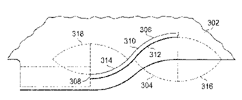
FIG. 3 is a schematic diagram showing an example of a rotorcraft yoke 300
(e.g., a
flexure or a composite retention element) with an embedded fiber optic cable
306.
The yoke 300 can include a primary section 302 which can include and/or be
made of
multiple composite fibers. The yoke 300 can also include a secondary section
304
attached to and protruding from the primary section 302. The primary section
302 can
be a flexure region or a primary structure that can bear a substantial portion
of the
6
CA 02894905 2015-06-17
load on the yoke 300. The secondary section 304 can be a low strain structural
attachment region which can bear a significantly smaller load relative to the
primary
section 302. The secondary section 304 can function as reinforcement for the
termination of the fiber optic cable 306 and/or as an attachment point for an
external
system that includes a mating sensor and that can connect to the cable 306 to
monitor the fiber optic cable 306. For example, the mating element can be a
cable
which ties to the monitoring unit, such as a fiber optic interrogator. In some
implementations, an edge of the yoke 300 can be machined to produce the
protruding
secondary section 304. The fiber optic cable 306 can be embedded within and
curve
ro around the body of the yoke 300, e.g., between layers of the primary
section 302 and
between layers of the secondary section 304. A length of the fiber optic cable
306
embedded between the layers of the primary section 302 can be oriented in a
primary
direction in which composite fibers of the primary section 302 extend. The end
of the
fiber optic cable 306 can terminate at a termination point 308 in the
secondary section
304 of the yoke 300.
FIG. 4 is a schematic diagram showing an orientation of the embedded fiber
optic
cable 306 in the yoke 300, e.g., a pass through yoke, a race track yoke, or
other yoke.
Techniques described below can be implemented with reference to other
rotorcraft
composites, e.g., rotorcraft composites in which embedded fiber optic cables
need to
be turned to reach a termination point. Examples of other rotorcraft
composites can
include a dog bone Link or bolt joint configuration. Other examples can
include
stringers or ribs used in both rotorcraft and fixed wing airframe
construction.
Additional examples of rotorcraft composites can include rotor blades,
airframe
structures such as spars, longerons, intercostals, skins, or other structural
elements
such as cylindrical or conical load-bearing elements, composite lugs,
composite
beams, or other composite materials.
As shown in FIG. 4, the fiber optic cable 306 is embedded in the primary
portion 302,
transitions from the primary portion 302 to the secondary portion 304, and
terminates
at the termination point 308 at the edge of the yoke 300, specifically, in the
secondary
portion 304. In some implementations, the length of the fiber optic cable 306,
e.g., a
portion of the length that transitions from the primary portion 302 to the
secondary
portion 304 (length 310), is oriented to include a curvature on the ply
boundary plane
between the layers of the yoke 300. The curvature can allow the fiber optic
cable 306
to gradually exit from the embedded location in the primary portion 302 toward
the
edge of the yoke 300 in the secondary portion 304 in a protected way that does
not
7
CA 02894905 2015-06-17
expose the structure or fiber to risk of failure initiation along the exit
path or at the exit
point. In some implementations, the portion of the length of the fiber optic
cable 306
can be curved in a substantially S-shape, between the layers of the yoke 300.
Alternatively, the curvature can have an L, C, U or any other shape. The
curvature,
e.g., the S-shape can minimize the wrinkling in the fiber optic cable 306 as
the cable
306 runs across in the thick part of the yoke 300. The curvature can cause the
fiber
optic cable 306 to remain in the same ply boundary plane as the remainder of
the
fiber optic cable 306 that is embedded in the primary section 302 of the yoke
300.
For example, the substantially S-shape can be defined by a first concave
portion 312
and a second concave portion 314. A direction of orientation of the first
concave
portion 312 can be opposite a second direction of orientation of the second
concave
portion 314. The first concave portion 312 and the second concave portion 314
can
represent circumferential portions of a first ellipse 316 and a second ellipse
318,
respectively. For example, the direction of orientation of the first concave
portion 312
is can track a circumference of the first ellipse 316. The direction of
orientation of the
second concave portion 314 can track the circumference of the second ellipse
318.
The bend radius of each concave portion can be defined by a ratio of the
maximum
radius and the minimum radius of the respective ellipse. For example, a ratio
of the
maximum radius to the minimum radius for the first ellipse 316 can be high,
e.g.,
greater than 5:1 such as approximately 10:1. In another example, an angle by
which
the fiber optic cable 306 turns along the second concave portion 316 can be
small,
e.g., less than or equal to approximately 7 degrees.
In general, the length 310 of the fiber optic cable 306 that transitions from
the load
bearing portion 302 to the non-load bearing portion 304 can be positioned in
any
orientation that decreases or eliminates an inter-laminar shear imparted to
the fiber
optic cable 36 by a sliding of two layers against one another. For example, a
portion
of the length 310 that transitions from the load bearing portion 302 to the
non-load
bearing portion 304 can be positioned with a gentle curve having a radius that
is at
least 100x the diameter of the fiber optic cable 306. Then, a portion of the
length that
traverses from the non-load bearing portion 304 to the termination point 308
can be
positioned with an opposing gentle curve having a similar radius. In this
manner, the
fiber optic cable 306 can be positioned with a low bend radius relative to a
90 degree
bend.
As described above, the length of the fiber optic cable 306 in the load
bearing portion
302 can be oriented in a primary direction in which composite fibers of the
yoke 300
8
CA 02894905 2015-06-17
are oriented. The length of the fiber optic cable 306 in the non-load bearing
portion
304 and near the termination point 308 can also be oriented in the same
direction as
the primary direction. The substantially S-shaped orientation can minimize the
shear
stress on the fiber optic cable 306 as the cable 306 transitions from the load
bearing
portion 302 to the non-load bearing portion 304.
FIGS. 5A-5C are schematic diagrams showing a portion of the yoke that includes
a
coil of the fiber optic cable 306. In some implementations, the end of the
length 310 of
the substantially S-shaped fiber optic cable can be terminated at the edge of
the yoke
300, e.g., at the termination point 308. Alternatively, an excess length of
the fiber optic
cable can placed in the yoke 300 for removal after curing the laminate. For
example,
FIG. 5A shows a schematic diagram of the yoke 300, in particular, the non-load
bearing portion 304, including multiple layers (e.g., a first layer 502, a
second layer
504, and/or other layers) of a plastic material, such as Tedtar() (offered by
DuPontTM,
Inc.) or other type of plastic material. The two layers of the plastic
material can be
formed into a storage section of the yoke 300. A coil 506 of the fiber optic
cable 306
can be included in the storage section. FIG. 5B shows a schematic diagram of
machining the composite rotorcraft material and the plastic material to access
the
storage section. The plastic material can be a temporary fiber storage
material in
which the coil 506 is stored prior to curing the yoke 300. FIG. 5C shows a
schematic
zo diagram of accessing the coil 506 in the storage section. The composite
rotorcraft
material and the plastic material can be machined to access an end of the coil
506. In
this manner, the coil 506 of the fiber optic cable 306 can be removed from the
edge of
the yoke 300. Including the coil 506 of the fiber optic cable 306 in the yoke
300 can
negate having to embed the end of the fiber optic cable 306 in the termination
point
308.
FIGS. 6A-6C are schematic diagrams showing an interface 600 into which an end
of
the fiber optic cable 306 is embedded. The interface 600 can be implemented to
connect the end of the fiber optic cable 306 at the termination point 308 to
an external
monitor, e.g., of the HUMS. For example, the fiber optic cable can be
connected to an
external light source and an external spectrometer to read returning light and
to
determine strain from the information represented by the light. The
interrogator can be
part of the HUMS or a separate unit which itself can be in communication with
the
HUMS. FIG. 6A is a schematic diagram showing the interface 600 embedded in the
yoke 300. The interface 600 can include a sleeve 602 positioned on the edge of
the
secondary section 304 of the yoke 300. When forming the yoke 300 and/or
positioning
9
CA 02894905 2016-11-24
the fiber optic cable 306 in the yoke 300, the sleeve 602 can be positioned at
the edge of
the secondary section 304 and the end of the fiber optic cable 306 can be
positioned in
the sleeve 602. In some implementations, a portion of the sleeve 602 can
protrude into
the secondary section 304 and a remainder of the sleeve 602 can protrude out
of the
secondary section 304. In this manner, the sleeve 602 can receive the end of
the fiber
optic cable 306.
FIGS. 6A and 6B are schematic diagrams showing a removable plug 604 positioned
in
the sleeve 602. The removable plug 604 can extend from a position within the
non-load
bearing portion 304 of the yoke 300 to a position that is external to the edge
of the yoke
113 300. In other words, the removable plug 604 can be positioned on either
side of the edge
of the yoke 300. The end of the fiber optic cable 306 can abut against the end
of the
removable plug 604 that is inside the non-load bearing portion 304 of the yoke
300. The
sleeve 602 can include one or more alignment members 606. For example, each
alignment member can be a ridge formed on an inner casing 605 of the sleeve
602. Prior
to curing, the fiber optic cable 306 can be inserted into the sleeve 602 such
that the end
of the fiber optic cable 306 contacts some of the alignment members when the
fiber optic
cable 306 is inserted into the sleeve 306. Subsequent to curing, the portion
of the sleeve
602 that protrudes out of the secondary section 304 can be machined such that
an outer
edge of the sleeve 602 coincides with the edge of the yoke 300. Because a
portion of the
removable plug 604 is positioned on either side of the edge of the yoke 300,
the sleeve
602 can be machined without affecting the end of the fiber optic cable 306.
FIG. 6C is a schematic diagram showing a machined surface of the yoke 300.
Subsequent to curing the yoke 300 and machining the sleeve 602, the portion of
the
removable plug 604 in the yoke 300 can be removed to expose the end of the
fiber optic
cable 306 and adjacent connection. In some implementations, alignment members
can
be formed on the inner casing 605 between the end of the removable plug 604
and the
end of the fiber optic cable 306. A fiber optic cable of a monitoring system
can be
inserted into the opening 608 formed by removing the machined plug 604. The
alignment
members formed in the inner casing 605 can align the fiber optic cable of the
monitoring
system with the end of the fiber optic cable 306. The sleeve 602 can utilize
any
commercially available or standardized connection type. In general, the sleeve
602 can
be any structure that can be implemented as a machine-able removable plug that
keeps
the connection free from damage after the curing process.
CA 02894905 2015-06-17
FIG. 7 is a flowchart of an example process 700 for forming a composite
rotorcraft
material. At 702, a length of a fiber optic cable is embedded between layers
of
composite rotorcraft fibers included in a composite rotorcraft material, e.g.,
a yoke. At
704, the length of the fiber optic cable is oriented in a substantially S-
shape between
the layers. At 706, an end of the length of the cable is extended to an edge
of the
composite rotorcraft fibers. At 708, the end of the length of the cable is
terminated at
the edge of the composite rotorcraft material. In some implementations, at
710, a
sleeve is positioned to receive the end of the length of the cable. At 712,
the layers of
the composite rotorcraft fibers are cured. At 714, a portion of the sleeve
that protrudes
out of the edge of the composite rotorcraft material is machined. At 716, the
plug can
be removed and a standard connector used to complete the optical circuit. The
external optical fiber that is connected to complete the optical circuit can
be housed in
a termination that affixes itself to the secondary section 304. The connector
can be,
e.g., a mechanical link, a clamped joint, a secondarily bonded joint, or any
other type
of connector.
In some implementations, a length of fiber can be stored in the secondary
portion 304.
At 718, the stored length of fiber can be retrieved and connected to an
external fiber
via a standard connection, e.g. a connector described above with reference to
step
716. If the connection breaks, e.g., the connection is severed, additional
stored fiber
can be retrieved from the secondary portion 304 and the step 718 can be
repeated. In
such implementations, the external connection may be rigidly affixed to the
secondary
portion 304 similarly to the removable plug 604.
A number of implementations have been described. Nevertheless, it will be
understood that various modifications may be made without departing from the
scope
of the disclosure.
11