Note: Descriptions are shown in the official language in which they were submitted.
CA 02894972 2015-06-12
WO 2014/111685 PCT/GB2014/050009
PIN JOINT ASSEMBLY
FIELD OF THE INVENTION
This invention relates to a pin joint assembly and in particular a pin joint
assembly for an
aircraft landing gear.
BACKGROUND TO THE INVENTION
For aircraft with retractable landing gear, each landing gear assembly
typically includes a
number of pin joint assemblies that allow separate elements of the landing
gear assembly to
pivot about the pin joint. Pin joints will typically be included in the side-
stay assemblies to
allow the upper and lower elements of the side-stay to pivot both with respect
to one
another and with respect to the main sliding tube of the landing gear and the
aircraft frame
itself
As the landing gear assembly can experience both lateral and longitudinal
loadings during
take-off and landing events it is normal for some deflection to occur in the
lugs of the side-
stays through which the pin joint passes. Such deflections are exacerbated in
modern side-
stay designs, which exhibit complex geometry to accommodate other landing gear
elements, such as springs and hydraulics, in order to reduce air resistance
and the risk of
bird strike when the gear is deployed. At present, the forces induced as a
result of these lug
deflections are reacted by the headed pin and nut or end cap of the pin joint
assembly that
passes through the lugs and allows the relative rotation of the two side-stay
elements.
Consequently, the headed pin and nut or end cap must be designed to be capable
of
carrying these deflection loads, with the necessary safety margin provided. To
achieve this
increased load carrying capability, the mass of the pin joint assembly is
increased
considerably. For example, for a mid sized commercial aircraft, this weight
difference is
typically around 2.5kg per pin joint. On dual stay landing gear assembly for
such an
aircraft with six pin joints, approximately 15kg may be added to the mass of
each landing
CA 02894972 2015-06-12
WO 2014/111685 PCT/GB2014/050009
2
gear assembly simply to provide the requisite additional load carrying
capability of the pin
joint assemblies. In addition to the increased manufacturing cost arising from
the larger
pin joint assemblies, this added weight is undesirable in terms of the overall
weight of the
aircraft as it has a direct bearing on the fuel efficiency of the aircraft. It
would therefore be
desirable to reduce the weight of a pin joint assembly without compromising
its load
carrying capability.
SUMMARY OF THE INVENTION
A pin joint assembly for an aircraft landing gear comprising: an elongate
joint pin; at least
one first lug through which the joint pin passes; and at least one second lug
through which
the joint pin passes; wherein the joint pin includes first and second
retaining elements
located at opposite ends of the joint pin and arranged to maintain the
location of the joint
pin relative to the first and second lugs, wherein at least a portion of the
pin joint is
elastically deformable.
Thus, any deflection of the first or second lugs may cause the portion of the
pin joint to
elastically deform such that the force exerted onto the pin joint is
significantly lower than
would be exerted if the portion was non-compliant. As a consequence of the
reduced load
transmitted from the lugs to elements of the pin joint assembly, these
elements can be
significantly reduced in size and weight in comparison with a pin joint
assembly of the
same load carrying capability with non-compliant elements of the pin joint
assembly, or
alternatively these elements can be kept the same size with an increased load
carrying
capability.
One or more of the first and second retaining elements may be secured to the
pin joint
assembly by one or more retaining bolts extending through the joint pin in a
direction
parallel to the longitudinal axis of the joint pin.
CA 02894972 2015-06-12
WO 2014/111685 PCT/GB2014/050009
3
One or more of the first and second retaining elements may be elastically
deformable.
Alternatively or in addition, one or more of the retaining bolts may be
elastically
deformable, preferably in a direction parallel to the longitudinal axis of the
joint pin, so
that they may comply with deflections of the lugs.
Preferably, at least one of the first and second retaining elements comprises
an end cap
secured to the joint pin. In which case, either or both end caps may be
secured to the one
or more retaining bolts by means of one or more retaining nuts threaded to
portions of
respective retaining bolts passing through the or each respective end cap.
Alternatively,
retaining bolts may comprise a head at one end and a thread at the other, such
that a single
end cap is used, secured to the bolt by a retaining nut threaded onto the end
of the retaining
bolt. In which case the head and/or end cap may be flexible.
One or more of the retaining elements, retaining bolts or joint pin may
comprise steel,
aluminium, or titanium.
In order to introduce compliance, one or more of the retaining elements may
have an axial
thickness of less than 5 millimetres.
According to a second aspect of the invention, there is provided an aircraft
landing gear
comprising a pin joint assembly as described with reference to aspects of the
present
invention.
BRIEF DESCRIPTION OF THE DRAWINGS
Embodiments of the present invention will now be described in more detail by
way of non-
limiting examples only, with reference to the accompanying figures, of which:
Figure 1 schematically illustrates a cross-section of a pin joint assembly
according to the
prior art;
CA 02894972 2015-06-12
WO 2014/111685 PCT/GB2014/050009
4
Figure 2 schematically illustrates a cross-section of an alternative pin joint
assembly
according to prior art;
Figure 3 schematically illustrates in cross-section a pin joint assembly
according to an
embodiment of the present invention.
DETAILED DESCRIPTION OF EMBODIMENTS OF THE PRESENT INVENTION
A pin joint assembly according to the prior art is schematically illustrated
in cross-section
in Figure 1. The pin joint assembly includes a pair of first lugs 2, 2a and a
second lug 4
interposed between the first lugs, and a joint pin 6 passing through the first
and second lugs
and about which the lugs can rotate. The joint pin 6 has an integral head 8
located at one
end of the pin preventing the pin from passing all the way through the first
and second
lugs, and has a threaded portion 10 provided at the opposite end to which a
retaining nut 12
is secured, thus completing the pin joint assembly. Any deflections in the
first and second
lugs 2, 2a, 4 caused by radial or axial loading of the pin joint, cause the
lugs to contact
either the pin head 8 or retaining nut 12 and consequently load the stiff
joint pin (bolt) 6
potentially to the point where the load is so high that the pin or the
retaining nut 12 will
fail. To prevent such failure the nut 12, and also pin head 8, must be
oversized so as to be
able to accommodate the additional lug deflection loadings over and above the
normal
operational loadings of the pin joint. This adds weight and cost to the pin
joint assembly.
An alternative pin joint also known the art is schematically illustrated in
plan view cross-
section in Figure 2. As with the pin joint assembly shown in Figure 1, first
and second
lugs 20, 20a & 22, 22a are provided through which a joint pin 24 extends. One
or more
retaining bolts 25, 25a extend through a bore or hollow section in the joint
pin 24 in a
direction parallel to the longitudinal axis of the joint pin 24 and may be
held in place at
either end by two retaining elements 26, 26a (also known as end caps) through
which a
portion of each of the one or more retaining bolts 25, 25a extends. The
portions of the
CA 02894972 2015-06-12
WO 2014/111685 PCT/GB2014/050009
retaining bolts 25, 25a that extend through the retaining elements 26, 26a are
threaded and
respective retaining nuts 28, 28a, 28b, 28c are fastened to the threaded
portions, thereby
securing the retaining elements 26, 26a in place and maintaining the physical
arrangement
of the pin joint assembly. As with the assembly shown in Figure 1, any
deflections of the
lugs 20, 20a, 22, 22a caused by radial loading of the pin joint 24, cause the
lugs 20, 20a,
22, 22a to contact one or both of the retaining elements 26, 26a. Because the
retaining
elements 26, 26a are substantially non-compliant, axial force applied by the
lugs to any
portion of the interior surface of the retaining elements 26, 26a is
transferred into the
retaining nuts 28, 28a, 28b, 28c and retaining bolts 25, 25a which secure the
joint pin 24 in
place. Consequently, the retaining elements 26, 26a, retaining nuts 28, 28a,
28b, 28c and
retaining bolts 25, 25a must again be oversized so as to accommodate lug
deflection
associated with abnormal operating loadings of the pin joint 24.
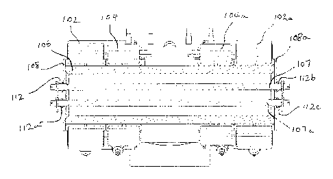
A pin joint assembly according to an embodiment of the present invention is
schematically
illustrated in plan view cross-section in Figure 3. As with the previously
illustrated pin
joint assembly of Figure 2, first and second lugs 102, 102a, 104, 104a are
provided through
which a joint pin 106 extends and one or more retaining bolts 107, 107a extend
laterally
through the joint pin 106 in a direction parallel to the longitudinal axis of
the joint pin 106.
However, the retaining elements 26, 26a illustrated in Figure 2 are replaced
with compliant
or flexible retaining elements 108, 108a. The portions of the retaining bolts
107, 107a that
extend through the compliant retaining elements 108, 108a may be threaded at
either end
and respective retaining nuts 112, 112a, 112b, 112c fastened to the threaded
portions or the
retaining bolts 107, 107a. Alternatively, each of the one or more retaining
bolts 107, 107a
may have a head at one end and a thread at the other, in which case a single
retaining nut is
required for each retaining bolt 107, 107a. As a further alternative, instead
of using
retaining bolts, each end of the joint pin itself may extend through a
retaining element 108,
108a.
In use, if the pin joint assembly in Figure 3 is loaded so as to induce a
deflection of the first
and/or second lugs 102, 102a, 104, 104a, this deflection causes the compliant
retaining
elements 108, 108a to elastically deform. Then, once the load is removed from
the stay
CA 02894972 2015-06-12
WO 2014/111685 PCT/GB2014/050009
6
and the lugs 102, 102a, 104, 104a return to their original position, the
retaining elements
108, 108a also return to their original position. Although the compression of
each of the
compliant retaining elements 108, 108a will still exert a force on its
corresponding
retaining nut(s) 112, 112a, 112b, 112c and retaining bolt 107, 107a, this
force is
significantly lower than would be exerted by the prior art retaining elements
26, 26a.
The load path in the pin joint assembly is indeterminate. Where indeterminate
load paths
are concerned, the stiffer an element is, the more load carrying capability it
has. Thus,
introduction of flex into the retaining elements means that, as the lugs
experience
deflection, less load is reacted through the retaining elements 108, 108a,
retaining nuts 112,
112a, 112b, 112c and retaining bolts 107, 107a, such load instead being
transferred and
reacted by the joint pin. As a consequence of the reduced load transmitted
from the lugs to
the retaining bolts 107, 107a and/or retaining nuts 112, 112a, 112b, 112cm,
these elements
can be significantly reduced in size and weight in comparison with a pin joint
assembly of
the same load carrying capability of the prior art. Furthermore, in order to
make the
retaining elements 108, 108a more compliant and flexible, they can be made
thinner, thus
further reducing the size and weight in comparison with the non-compliant
retaining
elements 26, 26a used in the prior art pin joint shown in Figure 2. Such thin
retaining
elements or end caps can be made from standard sheet metal, further reducing
costs
compared to thick end caps or heads, which need to be machined. Moreover,
since
retaining elements 108, 108a no longer need to withstand the forces applied by
deflecting
lugs, they need not be as strong.
The compliance of retaining elements may be reduced by reducing their
thickness. For
example, prior art end caps in stay pin joints which traditionally having a
thickness of
between 15 to 20 mm can be reduced in thickness to around 3mm. Alternatively
or in
addition, retaining elements could be manufactured from less stiff materials,
since the
retaining elements do not need to resist as much load as traditional retaining
elements. For
example, retaining elements could be made from materials such as aluminium or
titanium.
CA 02894972 2015-06-12
WO 2014/111685 PCT/GB2014/050009
7
In embodiments described above, the retaining elements or end caps are
designed to
comply with deflection of the lugs 102, 102a, 104, 104a. However, in other
embodiments
other elements of the pin joint assembly could be engineered to elastically
deform. For
example, retaining bolts 107, 107a could be replaced with one or more
retaining bolts
which are axially elastically deformable so that as the lugs deflect, applying
pressure to the
retaining bolts or retaining elements, compliance of the retaining bolts
absorbs forces
associated with the deflections.
By reducing the stiffness of the pin joint assembly of embodiments of the
present invention
by the introduction of compliance in retaining elements to absorb local
deflections, the
resulting pin joint assembly can be significantly smaller and lighter than the
corresponding
prior art pin joint assemblies. For example, for a typical dual stay aircraft
landing gear
with six joints approximately 15kg of weight reduction can be achieved using
pin joint
assemblies according to the present invention.