Note: Descriptions are shown in the official language in which they were submitted.
CA 2895007 2017-03-03
METHOD AND APPARATUS FOR NON-SPINDLE MULTI-AXIS MACHINING
FIELD OF THE INVENTION
[0001] This invention relates generally to tools and methods for machining
parts and, more
particularly, to machines that are capable of performing profiling operations.
[0002]
BACKGROUND
[0003] Milling is the machining process of using rotary cutters to remove
material from a
workpiece advancing or feeding in a direction at an angle with the axis of the
tool. It
covers a wide variety of different operations and machines, on scales from
small
individual parts to large, heavy-duty gang milling operations. It is one of
the most
commonly used processes in industry and machine shops today for machining
parts to
precise sizes and shapes.
[0004] Milling can be done with a wide range of machine tools. The original
class of machine
tools for milling was the milling machine which is often called "a mill".
After the advent
of computer numerical control (CNC), milling machines evolved into machining
centers
which are milling machines with automatic tool changers, tool magazines or
carousels,
CNC control, coolant systems, and enclosures), generally classified as
vertical machining
centers (VMCs) and horizontal machining centers (HMCs).
BRIEF SUMMARY OF THE INVENTION
[0005] Unlike the prior art machining techniques, the invention uses the non-
spindle controlled-
fracturing method to remove material from the workpiece without restriction to
a one-
dimensional work envelope. Controlled fracturing occurs when a material's
yield
strength and breaking strength are exceeded simultaneously. In other words,
strain is
instantaneous so there is no plastic deformation of the material being
machined.
1
CA 02895007 2015-06-19
Additionally, this also avoids attendant phenomena, like expansive heating and
strain-
hardening, which can chaotically complicate the machining process. Because
prior art
methods of contact machining are restricted to plastic deformation for
removing material
from a workpiece, complications are inherent in their operation and work to
severely
restrict performance in terms of productivity, precision, and applicability.
[0006] In order to avoid these shortcomings, the present invention's removal
of material by
controlled fracturing is useful for a number of reasons: (1) the present
invention can
remove material from a workpiece at a much higher rate by at least one or two
orders of
magnitude than prior art machining techniques; (2) the present invention
mitigates and
sometimes eliminates the chaotic effects of expansive heating and strain-
hardening
inherent in current methods of contact machining and so is more precise in the
fit and
finish it imparts to a part; (3) for the same reason, the invention can also
produce shapes
that are complex (e.g., highly curved airfoiling) and extreme (e.g., very thin
cross-
sections) that cannot be done using prior art machining methods; and (4) the
invention is
usable with materials, such as carbon fiber composites, which are typically
too brittle for
plastic deformation, i.e. their yield strength is identical to their breaking
strength and so
are difficult or impractical to machine by other prior art methods. Thus, a
purpose of the
present invention is to profile parts by means of contact machining more
rapidly and
precisely than existing art, including parts of shapes and materials that are
impractical or
impossible to profile with using machining techniques presently available in
the art.
[0007] Various embodiments of the present invention use non-spindle contact
machining not
known in prior art to induce controlled fracturing to profile workpieces into
finished
shapes. The invention combines the superior capabilities of turning and
milling without
the limitation of either. Generally, a lathe produces parts at faster material
removal rates
and with finer surface finishes than mill. However, the profiling operation of
a lathe is
restricted to a two-dimensional work envelope which limits the parts it can
produce to
those with circular cross-sections. A mill can profile within a three-
dimensional work
envelope, which permits the production of parts with a greater range of
shapes, although
at a slower material removal rate and with a rougher finish than a lathe. The
present
invention combines the advantages of the lathe and the mill in profiling
operations
2
CA 2895007 2017-03-03
without their limitations by producing parts with an unrestricted range of
shapes with
very fine surface finishes at high rates of material removal.
[0008] The profiling operations of lathes and mills are limited because they
rely upon the torque
produced by spindle rotation to cut away material from the workpiece. However,
spindle
rotation imposes symmetry about the axis of rotation upon either the shape of
the part to
be produced or the cutting tool used. In the case of the lathe, the workpiece
rotates and
the cutting tool does not. It is the need to rotate the workpiece that
restricts the lathe to a
two-dimensional work envelope and so limits the parts a lathe can profile to
those with
circular cross-sections, i.e., axial symmetry. In the case of the mill, the
cutting tool
rotates and the workpiece does not. This permits a three-dimensional work
envelope and
so the profiling of parts within a wide range of open and closed surfaces that
may be flat
or curved (including Bezier curves). However, the need to rotate the cutting
tool, which
imposes axial symmetry upon it, limits the shape and surface finish that a
mill can
produce on a workpiece and the material removal rate at which it can do so.
Moreover,
the rough surface finish left by milling often necessitates a secondary
grinding operation
or polishing by hand to create a finer finish on a part, therefore adding time
and expense
to its production.
[0009] Machine tools that profile by means of non-spindle methods exist in
prior art, including
planers, shapers, broaching machines and, more recently, U.S. Patent
Publication No.
U.S. 62003/0103829 to Suzuki et al. and Japanese Patent No. 63-123603 to
Koreda et al.
However, none of these machine tools are capable of roughing and finishing the
unrestricted range of shapes provided by the present invention. This is
because the
profiling operations these machine tools are either restricted to one-
dimensional cutting
paths within a two-dimensional work envelope or restricted to finish-machining
operations of open surfaces.
[0010] An example of the former restriction is Suzuki, which discloses a
method of cutting long,
straight rails made of hardened steel. In this method a static, i.e., a non-
rotating cutting
tool is fixtured at a starting point within a two-dimensional work envelope to
cut the
workpiece along a linear one-dimensional path. To cut along a different one-
dimensional
path, the tool must be re-fixtured at a different starting point within the
work envelope.
Like all other methods of non-spindle machining in the prior art, this device
is
3
CA 2895007 2017-03-03
constrained to a one-dimensional cutting path within a two-dimensional work
envelope.
It cannot produce the parts illustrated by 100 in FIG 3, 500 in FIG 15, and
500 in FIG 16.
Lacking three-dimensional motion within a three-dimensional work envelope,
none of
these non-rotary methods of machining can produce anything more than simple
shapes on
a workpiece and so have only highly specialized and severely limited
applications.
[0011] An example of the latter restriction is Koreda, which discloses an
apparatus for
modifying a conventional computer-numerical controlled machining center to use
a non-
rotating cutting tool to finish-machine a workpiece already roughed to near
net-shape by
another process to a three-dimensional shape restricted to open surfaces. This
invention
lacks the capability to produce a shape that has closed surfaces ¨ i.e., areas
that are
pocketed, concaved, stepped, or partially bounded by protrusions. For example,
the vane
102 relative to surface 104 in FIG. 3, the cavity 508 relative to the plane
defined by axes
502 and 504 in FIG 15, and the cavity 512 relative to the plane defined by
axes 502 and
504 in FIG 16. It can only produce surfaces that are open ¨ i.e., a flat or
gently curved
surface with no section that declines along the axis perpendicular to the
plane of the
surface. In other words, it cannot produce surfaces that require significant
plunging of
the cutting tool into the workpiece. Furthermore, this invention lacks the
capability to
both rough- and finish-machine a workpiece to net-shape. It is also limited,
at best, to
volumetric material removal rates typical of conventional methods of spindle
machining.
[0011.1] In accordance with one aspect of the present invention, there is
provided a non-spindle
multi-axis machining apparatus comprising a base section to which machine
components
are attached directly or by intermediary devices, at least one linear drive, a
plurality of
cutting tools affixed to at least one linear drive where the at least one
drive moves at least
one of the plurality cutting tools with sufficient force to induce controlled
fracturing, at
least one table affixed to the base for holding a workpiece in a fixed
position in relation
to the at least one table such that the at least one table moves independently
of the cutting
tool and is configured so the at least one linear drive moves the at least one
table in both a
vertical and horizontal axis relative to the base section, a programmable
controller
configured to cause a cutting edge of one of the plurality of cutting tools to
be in
operative engagement with the workpiece that is held by the table in order to
cause the
cutting edge to translate along an accurate path to cut the workpiece while
the cutting tool
4
CA 2895007 2017-03-03
is not rotated with a continuous milling-type rotation and while the workpiece
that is held
by the table is not rotated with a continuous turning-type rotation, and
wherein the at least
one cutting tool and the at least one table move relative to one another along
any three-
dimensional path within a work envelope of the machining apparatus for
profiling the
workpiece into a predetermined shape using a controlled fracturing process.
[0011.2] In accordance with another aspect of the present invention, there is
provided a non-
spindle multi-axis machining apparatus for use in plastic deformation and
controlled
fracturing processes comprising a base section to which machine components are
attached directly or by intermediary devices, at least one cutting tool
affixed to a flying
bridge such that the flying bridge is moveable relative to the base section,
at least one
linear drive, at least one table affixed to the base for holding a workpiece
into a fixed
position in relation to the table such that the table moves independently of
the at least one
cutting tool and where the at least linear drive is configured to move the at
least one table
in both a vertical and horizontal axis relative to the base section, and
wherein the cutting
tool and the table are synchronized to produce a movement of the cutting tool
through a
workpiece along any three-dimensional path within the work envelope of the
apparatus
by a microprocessor enabling a predetermined force to be applied to the
workpiece for
profiling the workpiece into a predetermined shape using a controlled
fracturing process.
[0011.3] In accordance with a further aspect of the present invention, there
is provided a non-
spindle multi-axis machining apparatus for machining a workpiece using a
controlled
fracturing process comprising a base section to which machine components are
attached
directly or by intermediary devices, a flying bridge connected to the base
section for
moving at least one cutting tool along a first axis of movement, at least one
table affixed
to the base for holding a workpiece in a fixed position in relation to the at
least one table
such that the at least one table moves independently of the cutting tool and
moves in both
a second axis and third axis, a microprocessor controller configured to cause
a cutting
edge of one of the plurality of cutting tools to be in contact with the
workpiece that is
held by the table in order to cause the cutting edge to translate along an
accurate cutting
path to cut the workpiece such that the cutting tool or the at least one table
is rotated with
a continuous turning-type rotation, wherein the at least one cutting tool and
the at least
one table move relative to one another along any three-dimensional path within
a work
4a
1
CA 2895007 2017-03-03
envelope of the machining apparatus for profiling the workpiece into a
predetermined
shape, and a first linear drive for moving the flying bridge in a first axis,
a second linear
drive for moving the table in the second axis, a third linear drive for moving
the table in a
third linear axis, and wherein the first linear drive, second linear drive and
third linear
drive move the cutting tool and workpiece with sufficient force to induce
controlled
fracturing of the workpiece and are each configured so the at least one linear
drive moves
the at least one table in a respective X, Y and Z axis relative to the base
section.
BRIEF DESCRIPTION OF THE DRAWINGS
[0012] The present invention will now be described with reference to the
accompanying
drawings wherein like reference numerals in the following written description
correspond
to like elements in the several drawings identified below.
[0013] FIG. 1 is a perspective view of a prior art machined part that can be
produced by the non-
spindle multi-axis machining method of the present invention.
[0014] FIG. 2 is part view of the part depicted in FIG. 1 as machined by prior
art milling
techniques.
[0015] FIG. 3 is a partial view of the part depicted in FIG. 1 as machined by
the present
invention.
4b
CA 02895007 2015-06-19
[0016] FIG. 4 is a front view of a non-spindle cutting tool used in accordance
with an
embodiment of the present invention to machine the part as depicted in FIG. 3.
[0017] FIG. 5 is a side view of the tool depicted in FIG. 4.
[0018] FIG. 6 is an elevation view of a prior art tool used in accordance with
a prior art mill to
machine the part as depicted in FIG. 2.
[0019] FIG. 7 is a bottom view of the tool depicted in FIG. 6.
[0020] FIG. 8 is a bottom view of the prior art tool depicted in FIGs. 6 and 7
as used to machine
a part.
[0021] FIG. 9 is a front view of a non-spindle cutting tool used in accordance
with various
embodiments of the present invention.
[0022] FIG. 10 is a side view of the tool depicted in FIG. 9.
[0023] FIG. 11 illustrates perspective views of different insertable cutting
edges for the tool
depicted in FIGs. 9 and 10.
[0024] FIG. 12 is a front view of an axially asymmetric non-spindle cutting
tool used in
accordance with various embodiments of the present invention.
[0025] FIG. 13 is a side view of the tool depicted in FIG. 12.
[0026] FIG. 14 is an elevation view of the tool depicted in FIGs. 9 and 10
being used to machine
a part in accordance with one aspect of the present invention.
[0027] FIG. 15 is a perspective view of a part machined in accordance with the
"3-axis"
embodiment of the present invention.
[0028] FIG. 16 is a perspective view of another part machined in accordance
with the "4-axis"
embodiment of the present invention.
[0029] FIG. 17 is a perspective view of a non-spindle machining apparatus in
accordance with
the "3-axis" and "4-axis" embodiments of the present invention.
[0030] FIG. 18 is a flow chart of the non-spindle machining method of the
present invention
machining the part depicted in FIG. 15 in accordance with the "3-axis"
embodiment of
the present invention.
[0031] FIG. 19 is a flow chart of the non-spindle machining method of the
present invention
machining the part depicted in FIG. 16 in accordance with the "4-axis"
embodiment of
the present invention.
CA 02895007 2015-06-19
[0032] FIG. 20 is a flow chart of the non-spindle machining method of the
present invention
machining a complex surface, such as a NURBS surface, in accordance with a "5-
axis" or
"7-axis" embodiment of the present invention.
[0033] F1Gs. 21A, 21B and 21C are chart diagrams illustrating elastic,
plastic, and controlled-
fracture phases respectively of deformation.
[0034] FIG. 22 is a perceptive view of a non-spindle vertical machining center
using linear
drives to achieve controlled fracturing in accordance with alternate
embodiments of the
invention.
[0035] FIG. 23 is a side view of that illustrated in FIG. 22 where the machine
tool is not engaged
with the workpiece.
[0036] FIG. 24 is a side view of that illustrated in FIG. 22 where the machine
tool is engaged
with the workpiece.
[0037] FIG. 25 is a side view of that illustrated in FIG. 22 where the flying
bridge and cutting
tool is adjacent to the workpiece.
[0038] FIG. 26 is a side view of that illustrated in FIG. 22 where the flying
bridge and cutting
tool are engaged with the workpiece.
[0039] FIG. 27 is a block diagram showing microprocessor control of linear
drives used in
connection with the invention.
DETAILED DESCRIPTION
[0040] There are two basic machining operations that are well known in the
art. These might be
broadly categorized as "profiling" where material is removed from a workpiece
to
produce a specified shape and surface finish and "holemaking" where material
is
removed from a workpiece to produce a drilled, tapped, or counter-bored hole.
With
regard to profiling, in order to profile a workpiece, there are three basic
processes for
removing material from a workpiece viz, deformation, electrolysis and
ablation.
Deformation is a process where a cutting tool, having at least one cutting
edge, removes
material from a workpiece by direct contact. This process is the least
restricted in the
shapes and materials that can be cut by the cutting tool. The "turning" and
"milling"
processes are the most common examples of deformation. Electrolysis is a
process where
a cathode electrochemically dissolves material from an anodized workpiece.
This
6
CA 02895007 2015-06-19
process is restricted to electrically conductive materials. Electrochemical
and electrical
discharge machining are examples of electrolysis. Finally, ablation is a
process where a
beam of energy vaporizes or erodes material from a workpiece. The ablation
process is
limited to flat work that lacks the requirement for three-dimensional
features. Laser and
waterjet cutting are examples of the ablation process.
[0041] In order to remove material by deformation, or sometimes called
"contact machining",
there are two basic methods. The first method is rotation of either the
cutting tool or the
workpiece about a spindle to provide sufficient torque to remove material. In
turning, the
workpiece rotates as the cutting tool moves through it. In milling, the
cutting tool rotates
as it moves through the workpiece. Spindle methods of machining impose axial
symmetry upon either the cutting tool or the workpiece and thus limit
volumetric rates of
material removal, producible shapes, and precision of the finished part. The
second
method does not use a spindle. Neither the cutting tool nor the workpiece
rotates. The
force of linear motion of the tool relative to the workpiece alone is
sufficient to remove
material. However, unlike the spindle methods of machining, this method is
severely
restricted the shapes that can be produced. Shaping, planning, and broaching
are
examples of non-spindle methods of machining by deformation.
[0042] An embodiment of the present invention is directed to 1) driving a
cutting tool through a
workpiece without rotation by a spindle at a sufficiently high speed to remove
material by
means of controlled fracturing (2) along a three-dimensional path within a
three-
dimensional work envelope to produce precision flat and curved shapes with
both open
and closed surfaces (3) first by rough-machining the workpiece to near net-
shape and (4)
then finish-machining it to completion with a surface finish of 4 to 16
mieroinehes or
finer (5) at material removal rates of 20 cubic inches per minutes or more at
feed rates of
5,000 inches per minute or more (6) without the expense of secondary
operations and
manual labor.
[0043] Comparison with the Prior Art. The present invention is distinguished
from current
spindle and non-spindle machining methods and apparatuses for profiling
operations by:
(1) A non-rotating cutting tool that is unconstrained by axial symmetry (2)
driven along a
one-, two-, or three-dimensional cutting path (3) within a three-dimensional
work
envelope (4) to remove material from a non-rotating workpiece (5) at a
sufficiently high
7
CA 02895007 2015-06-19
speed to induce controlled fracturing to remove material without torque. No
other
method or apparatus for machining possesses all of these characteristics. As a
consequence of these characteristics the present invention can: (1) rough-
machine a
workpiece to near net-shape and then precisely finish-machine it (2) to an
unrestricted
range of shapes with both open and closed surfaces, (3) including those with
thin cross-
sections, (4) at very fine surface finishes (5) at high volumetric rates of
material removal.
No other method or apparatus for machining can produce these results on a
single
machine tool in a single profiling operation. The comparison of these
characteristics and
capabilities between the present invention and prior art are illustrated in
Table 1 below.
TABLE 1 - COMPARISON OF CURRENT MACHINING METHODS TO NON-SPINDLE
CONTROLLED-FRACTURE MACHINING METHOD
1-D 2-D 3-D 2-E1 3-D Comple Thin F Rapid
Method Tool Tool Tool Work Work ine Cross-
Mat'l
Finish
Path Path Path Envelope Envelope Shapes Sections
Removal
Non-
Spindle
X X X X X X X X X
Controlled
Fracturing
Milling X X X X X X
Turning X X X X X X
Shaping X X X
Planing X X X
Broaching X X
Suzuki X X
Koreda X X X X X
8
CA 02895007 2015-06-19
[0044] The present invention is most directly compared to the profiling
operations of mills,
because it mostly obsoletes the need for such. The primary utility a mill will
retain is
hole-making within a three-dimensional work envelope. The reason for this
obsolescence
is that the non-spindle machining method of the present invention can execute
any
profiling operation that a mill can: (1) Without any restriction of the shape
required for
the part (2) with a finer lathe-like surface finish, thus eliminating or
reducing the need for
grinding or polishing, (3) at material removal rates generally five to forty
times faster.
These advantages are a direct consequence of the present invention which does
not
require torque produced by a spindle as a force sufficient to remove material.
This
difference is well demonstrated by the significantly increased material
removal rates of
the present invention, as will be fully described later. Furthermore, an
apparatus
embodying this method will generally be less expensive, less complex, and
sturdier than
a comparable mill.
[0045] Unrestricted Range of Shapes. Despite their significant disadvantages
mills are
presently used to machine parts with complex shapes, such as large die sets
used in the
automotive industry to form car roofs, hoods, and fenders or smaller precision
components like impellers or the like. For example, FIG. 1 illustrates a
perspective view
of a prior art impeller 100 that can be produced by the non-spindle multi-axis
machining
center and methods of the present invention. The area depicted by "II"
indicates a close-
up as shown in FIG. 2 while the area "III- indicates that shown in the FIG. 3.
Those
skilled in the art recognize that amongst existing machine tools, mills are
the least
restricted in the shapes they can produce in a profiling operation. However,
the need to
rotate the cutting tool imposes the constraint of axial symmetry upon it.
That, in turn,
restricts to the shape of the tool the range of shapes that a mill can cut
into a workpiece.
[0046] As specifically seen in FIG. 2 and FIG. 3 the differences in the type
of cut using prior art
milling techniques and the non-spindle machining method of the present
invention are
clearly illustrated. FIG. 2 illustrates a close-up of the type of cut as used
with prior art
milling techniques that create a radius between edges while FIG. 3 uses
present
machining methods to create an orthogonal edge. With regard to FIG. 3, an
example of
the process creates an orthogonal interior corner formed by the intersection
of two curved
surfaces. This type of surface cannot be produced using prior art milling
techniques.
9
CA 02895007 2015-06-19
Both FIGs. 2 and 3 illustrate an impeller 100 utilizing a series of vanes 102
that extend
outwardly from a concave surface 104. As shown in FIG. 3, the intersection of
a vane
102 and the surface 104 creates a sharp inside corner 106.
[0047] FIG. 4 is a front view of a non-spindle (i.e., non-rotating) cutting
tool used in accordance
with an embodiment of the present invention used to machine the part as
depicted in FIG.
3. FIG. 5 is a side view of the tool depicted in FIG. 4. Because the machining
method of
the present invention employs a non-rotating cutting tool 200, axial symmetry
is not a
requirement for the tool. Therefore, the tool 200 does not need to be relieved
in all
directions to clear the curved surfaces 102 104 of the impeller 100. The tool
200 needs
only to be relieved on the posterior side 206 that is perpendicular to the
direction of its
cutting path. Therefore, the tool's cutting edge 202 can feature a sharp
corner 204 which
can be continuously re-oriented along the cutting path of the corner 106, by
means of the
present invention, to machine it as specified. For this reason, the present
invention,
unlike a mill, is unrestricted in the shapes it can cut in a profiling
operation.
[0048] FIG. 6 is an elevation view of a prior art tool used in accordance with
a prior art mill to
machine the part as depicted in FIG. 2. FIG. 7 is a bottom view of the tool
depicted in
FIG. 6. In order to cut the side of the vane 102 and the concave curve of the
surface 104
to specification, a mill must use an axially symmetrical cutting tool like
that shown in
FIG. 6. As seen in FIGs. 6 and 7, the tool 300 includes a spherical nose 302
and cutting
edge 304. The tool 300 is relieved in all directions to clear the curved
surfaces 102, 104
specified for the impeller 100. FIG. 2 illustrates the prior art techniques
where the vanes
102 and the concave surface 104 of the milled impeller 100 are to
specification. Instead
of the sharp inside corner 106 as seen in FIG. 3, at their intersection is a
large radius 108
conforming to the spherical nose 302 of the mill's rotating cutting tool.
[0049] Finer Surface Finishes. Even when a mill can profile a shape to its
specified
dimensions, it will leave a rough or scalloped edge. As noted above, prior art
FIG. 8
illustrates the cutting tool 300 as frequently used by a mill in profiling
operations. The
tool 300 includes a number of cutting edges 304, called flutes, which cut
material away
from the workpiece 306 as the tool 300 rotates. Because the flutes 304 are
spaced apart
from each other, material is not cut away constantly from the workpiece 306.
Instead, the
material is only cut away during the time when one of the four flutes 304 is
in contact
CA 02895007 2015-06-19
with the workpiece 306. Consequently, the removal of material by the rotating
tool 300
is not consistent as it moves through the workpiece 306. The result is an
uneven surface
marked by a series of scallops 308. If these scallops 308 are excessive or
otherwise
unwanted, it is necessary to grind or manually polish the workpiece 306 after
completion
of the profiling operation on the mill to produce a sufficiently fine finish
on the
completed part.
[0050] FIG. 9 is a front view of a non-spindle cutting tool used in accordance
with various
embodiments of the present invention while FIG. 10 is a side view of the tool
depicted in
FIG. 9. Unlike the flutes 304 of a mill's rotating cutting tool 300, FIGs. 9-
10 illustrate
the non-rotating tool 400 with a cutting edge 404 that, when employed by the
present
invention in a profiling operation, is in constant, stable contact with the
workpiece 500 as
depicted in FIG. 14. As a result, there are no scallops left on the cut
surface of the
workpiece 500. For this reason, the present invention produces a much finer
surface
finish in a profiling operation than a mill does, thus eliminating or reducing
the need for
subsequent grinding or polishing.
[0051] Faster material removal rates. FIG. 11 illustrates perspective views of
different
insertable cutting edges for the tool depicted in FIGs. 9 and 10.
Alternatively to that
shown in FlGs. 9-10, the non-spindle cutting tool 400 may include a cutting
edge 404
that is either inserted into or integral to the tool body 402. It should be
evident to those
skilled in the art that the cutting edge 404 is illustrated as a "circular
edge" that may be
altered to a sharp point, square face 408 or other geometries such as shown in
FIG. 11 to
machine the desired shape and surface finish on a workpiece.
[0052] FIG. 12 illustrates a front view of an axially asymmetric non-spindle
cutting tool used in
accordance with various embodiments of the present invention. FIG. 13 is a
side view of
the tool depicted in FIG. 13. The tool body 412 can be of any shape necessary
to support
the cutting edge 404 while providing relief for it to machine deep or other
spatially
constrained features into a workpiece. An example of this tool body is
illustrated in
FIGs. 12-13. Often a non-rotating cutting tool 400 such as that depicted in
FIGs. 9-10
will be the same as, or similar to, cutting tools used for turning. This is
due to the fact
that the non-spindle machining method of the present invention does not
restrict the
operation of the tool as does turning to a two-dimensional cutting path within
a two-
11
CA 02895007 2015-06-19
dimensional work envelope. Therefore, a non-rotating cutting tool can possess
cutting
edges, tool body shapes, and asymmetrical features not found in turning tools
to machine
complex shapes not possible with turning.
[0053] FIG. 14 illustrates a non-spindle cutting tool 400 removing material
from a workpiece
500 in accordance with an embodiment of the present invention. Once in contact
with the
workpiece 500 the cutting edge 404 of the tool 400 is continuously engaged in
a uniform
cutting motion that removes material with a constant force. This is in sharp
contrast to
the variable force of the rotating cutting tool 300 used by a mill in a
profiling operation,
as depicted in FIG. 8. In that instance each flute 304 of the tool 300 rotates
towards the
workpiece 306 and swings from no engagement to full engagement to no
engagement
again. The variation in force is the result in the change of the chip load of
the tool 300 as
the mass of material that the flute 304 is removing increases from zero to
full chip load to
zero again. Furthermore, the force of a rotating cutting tool 300 also varies
because its
acceleration decreases from maximum surface footage at its outside diameter to
zero at
its centerline, so that the nature of its cutting motion ranges from shearing
at the
maximum radial extent of the flute 310 to tearing along most the flute's edge
312 to
scraping along its bottom 314 to pushing through material at its center 316.
[0054] The difference between the two types of cutting motions is that a
rotating cutting tool 300
leaves a series of scallops 308 from side-cutting on the surface of the
workpiece 306 and
a rough finish from bottom-cutting, whereas a non-rotating cutting tool 400
leaves a
smooth finish on the workpiece 500. This is because the variable force of a
rotating
cutting tool 300 has the effect of mostly tearing material away from the
workpiece 306
rather than shearing it as does a non-rotating cutting tool 400 from the
workpiece 500.
Additionally, by shearing material with constant force to remove it rather
than tearing it
away with variable force, the non-spindle multi-axis machining method can
produce parts
with thinner cross-sections more precisely, more quickly, and with less scrap
than is
possible with milling. Also, shearing instead of tearing keeps the heat from
the friction
of the cutting motion in the chip rather than the cutting tool 400 or the
workpiece 500,
which improves tool life and reduces defects and distortions in the finished
part,
especially those with complex shapes or thin cross-sections. Less obvious is
that the
variable force of a rotating cutting tool 300 introduces a much larger element
of chaos
12
CA 02895007 2015-06-19
into the cutting motion than does the constant force of a non-rotating cutting
tool 400.
This disorder, often manifesting itself as chatter, increases the
unpredictably of a
profiling operation on a mill compared to the present invention and therefore
significantly
restricts the range, performance, and productivity of mills even for simple
operations.
The constancy of force in the cutting motion of a non-rotating cutting tool
400 along a
three-dimensional path through a three-dimensional work envelope is the
essence of the
present invention which cannot be replicated by any machining method or
apparatus of
prior art.
[0055] The stable, constant cutting force that the present invention applies
through a non-
rotating cutting tool ensures that energy is not drawn away from the task of
material
removal in the form of chaotic motion such as chatter. Therefore, constancy of
the
cutting force is critical to increasing the material removal rate of the
present invention in
comparison to milling. Even more fundamental to the present invention's
significantly
faster material removal rates is that, unlike a mill, none of the cutting
force delivered to
the cutting tool is torque. Because the rate of material removal is the result
of the depth
of cut multiplied by the width of cut multiplied by the cutting tool's linear
rate of the
motion through the workpiece, the torque of rotating tool is not a direct
factor.
Consequently, the cutting force that a mill delivers as torque is a force that
does not
contribute significantly to the linear rate of motion of the cutting tool
through the
workpiece. Table 2 compares the non-spindle method of the present invention to
milling
for four common machining operations using the best practices for each to
illustrate the
greater material removal rates of the present invention by factors of 12, 23,
33, and even
200. For this and the other reasons stated above, the present invention can
remove
material from a workpiece in profiling operations at rates generally 5 to 40
times faster
than a mill.
13
CA 02895007 2015-06-19
TABLE 2 - COMPARISON OF MATERIAL REMOVAL
RATES FOR TYPICAL ALLOY STEEL WORKPIECE
Non-
Depth Width Material
Spindle /
of of Cutting
Removal Milling
Machining Cutting Cut Cut Speed Feed Rate
Rate Comparis
Operation Method Tool 1 (mm) (mm)
(m/min.) (m/min.) (c.c./min.) on
110mm
dia.
milling per carbide
0.25 100 150 2.0 50.0
prior art inserted
surface
surfacing 12
mill
20mm dia.
non-spindle
carbide
per present 6.5 1.5 n/a 60 582
invention inserted
cutter
20mm
milling per
dia.carbide 10 18 45 0.18 32.4
prior art
end mill
side lOmm
23
milling non-spindle wide
per present carbide 3.3 7.5 n/a 30 743
invention inserted
cutter
20mm
carbide
milling per
inserted 3.3 4 300 1.5 19.8
prior art
ball-nose
rough
end mill 33
contouring-
20mm dia.
non-spindle
carbide
per present 6.5 3.3 n/a 30 644
invention inserted
cutter
3mm dia.
milling per carbide
0.6 0.25 120 1.0 0.15
prior art ball-nose
finish end mill
200
contouring 3mm dia.
non-spindle
carbide
per present 1.0 0.25 n/a 120 30
inserted
invention
cutter
14
CA 02895007 2015-06-19
[0056] Deformation by controlled fracturing. The invention's high volumetric
rate of material
removal are made possible by inducing controlled fracturing in the workpiece.
FIGs.
21A, 21B and 21C are charts illustrating the nature of the elastic, plastic,
and controlled-
fracture phases of deformation. As seen in these charts, depending upon the
force driving
the cutting tool through the workpiece, the present invention removes material
from the
workpiece by either plastic deformation 1004 or controlled fracturing 1023. In
both
cases, it does so at volumetric rates of material removal one or two orders of
magnitude
greater than that of existing art. However, controlled fracturing 1023 is the
superior
process, because it mitigates or eliminates the expansive heating and strain-
hardening that
characterize plastic deformation 1004. These effects cause difficulties in the
machining
process by degrading speed and precision; limiting the range of shapes and
materials that
can be machined; shortening machine and tool life; and destabilizing
production with
unpredictable factors. To the extent that the cutting force that the present
invention
applies to the material of a workpiece approaches instantaneous strain 1021,
and achieves
controlled fracturing 1023, the period of plastic deformation 1004 is reduced
and so are
its adverse effects.
[0057] As described herein, controlled fracturing 1023 offers the ideal level
of deformation in a
profiling operation, and is the process of contact machining that works to
achieve certain
predefined goals. As seen in each of FIGs. 21A and 21C, deformation of a
ductile
material occurs at three levels 1003, 1004, and 1023. The first level is
elastic
deformation 1003, in which the material will return to its original shape once
it is relieved
of stress. If the stress exceeds the material's yield strength 1001, then the
second level,
plastic deformation 1004, is reached and the material is permanently deformed.
The
continued application of stress to a plastically deformed material will cause
strain to
accumulate 1005 until it exceeds the material's breaking strength 1002
allowing it to
rupture 1006. For the methods of contact machining in existing art, this level
of
deformation is the best that can be achieved and is observed as the cutting
tool 300
operating to separate irregularly chipped material 308 from a workpiece 316.
[0058] Generally, the longer it takes strain to accumulate 1005, the greater
are the effects of
expansive heating and strain-hardening, and the more severe is the resulting
chaos in the
material removal process. Therefore, reducing or even eliminating the time it
takes the
CA 02895007 2015-06-19
accumulation of strain 1005 to rupture 1006 a material is desirable. Thus, the
ideal is
instantaneous strain 1021, in which a material's yield strength 1001 and
breaking strength
1002 are exceeded at the same time. This, in effect, makes a ductile material
1000
behave like one that is brittle 1010, in which no plastic deformation 1004
occurs as a
cutting tool 400 removes material from a workpiece 500, as graphed in FIG.
21B.
Instead of pulling a material apart by rupturing it 1006, the force of the
cutting tool
cracks 1022 the workpiece along lines of fracture to separate pieces of
material, as seen
in FIG. 21C. This process is termed ''controlled fracturing" 1023, which is
the third level
of deformation. The shape, orientation, and direction of the tool's cutting
edge determine
how the material will fracture 1022 by concentrating the heat generated from
the cutting
tool's 400 contact with the workpiece 500 into adiabatic bands emanating from
the
perimeter of the cutting edge 404 in the direction of the cutting tool's
motion. The
heating within these bands causes micro-cracks to form which then connect
under the
continued stress of the cutting force and fractures material loose from the
workpiece
along a line conforming to the perimeter of the cutting edge 404 406 408. The
present
invention controls these cutting tool factors to produce the desired shape and
finish
without the adverse effects of plastic deformation 1004 that limit the
performance of all
other methods of contact machining in existing art.
[0059] Thus, embodiments of the present invention induce controlled-fracturing
in the
workpiece by an abrupt, localized, and extreme force of the cutting tool
against the
workpiece that exceeds the ultimate shear strength of the material of the
workpiece. This
force is in the form of an impact which, because of the speed at which the
cutting tool
moves through the workpiece, the material of the workpiece does not have time
to
respond by deforming plastically and instead fractures. The fracturing is
controlled by
maintain the speed and direction of the cut and the outside contour of the
cutting tool. To
wit, shear bands form in the workpiece as a microstructure of cracks emanating
in the
direction of the cutting tool within the outside contour of the cutting tool
as projected into
the workpiece. Under the continued impact of the cutting tool moving through
the
workpiece, this microstructure softens relative to the uncut material
surrounding it,
because the cracked material becomes highly fractured, even to the point of
recrystallizing. Once softened the cutting tool shears this material from the
workpiece as
16
CA 02895007 2015-06-19
waste retaining almost all of the heat generated by the process, because its
microstructure
of cracks retards the transfer of heat to material outside of the
microstructure. The end
result of this controlled-fracturing process is a shape cut into the workpiece
with the same
contour as the cutting tool.
[0060] The force sufficient to propagate the shear bands for controlled-
fracturing varies with the
material of the workpiece. The cutting tool must apply at least 60,000 pounds
of force
per square inch of areal contact with the workpiece if it is cold-rolled mild
steel; 80,000
pounds for alloy steel; 150,000 pounds for stainless steel; 50,000 pounds for
titanium;
20,000 pounds for aluminum; and 50,000 pounds for aluminum-bronze. The methods
defined herein apply these forces without a spindle in three or more
dimensions
simultaneously. Consequently the only restrictions upon the volumetric rate of
material
removal are the surface footage, depth of cut, and width of cut limitations of
the cutting
tool. This distinguishes the invention from machining processes in prior art,
in which the
volumetric rate of material removal is restricted by the cutting tool's
limitations, the
imposition of axial symmetry by the machine tool's spindle, and/or the absence
of a
second or third dimension in the machine tool's work envelope. The end result
is the
optimization of the cutting tool's performance to its ideal.
[0061] Terms of Art. With regard to the open and closed surfaces as described
herein, those
skilled in the art will further recognize that the method described herein
will inherently
machine a closed surface. An open surface may be defined as the flat, sloping,
convex,
or similar surfaces of a workpiece that can be machined without any motion (or
any
component of multi-axis motion) along a cutting path toward the workpiece. The
term
"plunging" is a cutting path that has a component of motion toward the
workpiece. A
"closed surface" is either one that requires "plunging" to machine or one in
which
another surface interferes with the plane perpendicular to it. As compared to
the prior art,
an advantage of the present invention is techniques as used in the prior art
are limited to
machining only open surfaces.
[0062] With regard to straight versus curved cutting paths, machining along a
straight cutting
path is a capability inherent in a curved path. Those skilled in the art will
recognize that
a curved cutting path is in fact a series of extremely short straight paths
arranged and/or
oriented in a "stair step" manner and is often used in connection with a
numerical-
17
CA 02895007 2015-06-19
controlled mill or lathe. Thus, an aspect of the controlled fracturing process
is that in the
absence of axial symmetry imposed upon either the cutting tool or the
workpiece by the
spindle of a mill or lathe, a cutting tool of unrestricted shape can move in
any cutting path
allowing for precision removal of material producing either a roughed surface
(i.e. near
net-shape) or a finished surface (i.e. exact net-shape) on the workpiece.
[0063] With regard to the processes or roughing versus finishing, the process
of "roughing"
means to machine to near net-shape with a surface that is "less fine" (a
machining term of
art) than the finish specified for the completed surface at net-shape. A
cutting tool used
for roughing removes material from the workpiece faster than a cutting tool
used for
finishing. This occurs since the tool's cutting edge typically has a greater
radius and
therefore can make cuts at greater volumetric rates of removal through the
workpiece. In
addition to the appropriate cutting tool, roughing requires a machine tool,
fixturing of the
workpiece to the machine tool, and fixturing of the cutting tool to the
machine tool that is
sufficiently rigid to prevent vibrations from the motion of the cutting tool
through the
workpiece from distorting the intended cutting path. In contrast to the prior
art, the
methods of controlled fracturing are not restricted to finishing and can be
employed for
both "roughing" and "finishing" to the extent that a particular combination of
machine,
fixture, and cutting tool makes possible.
[0064] As for processes using rotation and rotary motion, those skilled in the
art will recognize
that a "spindle" is not a "rotary axis. The term "rotation" means rotation of
a machine
tool's spindle. This rotation produces sufficient torque for a cutting tool to
remove
material from a workpiece. The force provided by rotation is applied either by
attaching
a cutting tool to the spindle (as in a milling process), or by attaching a
workpiece to the
spindle (as in a turning process). Machining with a spindle imposes axial
symmetry upon
either the cutting tool (as in milling) or the workpiece (as in turning).
Axial symmetry is
symmetry around the axis of a rotating spindle. Axial symmetry greatly
restricts the
finished shape of the workpiece, the volumetric rate of material removal, and
the fineness
of the surface finish. It also increases chaos in the movement of the cutting
tool relative
to the workpiece. Milling and turning as methods of spindle machining suffer
these
problems in contrast to the non-spindle method of controlled-fracture
machining.
Because it does not impose axial asymmetry upon either the cutting tool or the
18
CA 02895007 2015-06-19
workpiece, it is a method of machining all surfaces along three-dimensional
cutting paths
without the limitations in volumetric rate of material removal, finished
shapes, fineness
of surface finishes, and chaotic motion that are inherent in spindle
machining.
[0065] "Rotary-axis motion" is unrelated to spindle rotation. It is the
rotation of a linear axis,
conventionally labeled as the A-axis, B-axis, and C-axis in correspondence
with the
associated linear axes X, Y, and Z. Rotary-axis motion does not to produce
torque to
increase cutting force, which is the purpose of spindle rotation. Instead, it
either indexes
or continuously changes the "orientation" of the cutting tool ¨ i.e., the
angle of the face of
the cutting tool relative to the surface being machined on the workpiece.
Those skilled in
the art will also recognize that the term "torque" means a twisting force
applied to the
workpiece and the term "orientation" can also be expressed in terms of the
cutting edge
of the cutting tool, although as a term of art the reference is typically to
the face of the
tool. Rotary-axis motion is a component, like linear-axis motion, of the
cutting path.
With regard to the terms "precision" and "fine finish", as used herein
"precision" means
how closely the workpiece is machined is to within the tolerances of the
specified
dimensions of the completed part i.e. net-shape. "Fine finish" means how
closely the
workpiece is machined to the specified surface finish of the completed part.
The term
"controlled fracturing" occurs when the strain in a workpiece accumulates
instantaneously under the force of the cutting tool. In other words, the time
it takes strain
to accumulate between the point of elasticity and the break point is zero.
This occurs in
brittle materials because they have no elasticity. The result is chaotic
rupturing of the
materials. However, in controlled fracturing, non-brittle materials behave
like brittle
ones except that the rupturing is not chaotic. This is because their
plasticity allows the
shape of their rupturing to be controlled by the cutting edge of the cutting
tool. Finally,
those skilled in the art will further recognize that each cutting path is
independent of the
previous path; therefore, it is not the multiplicity of paths but their
unrestricted movement
along a machine tool's linear or rotary axis, or simultaneously along more
than one axis,
which makes the controlled fracturing process unique.
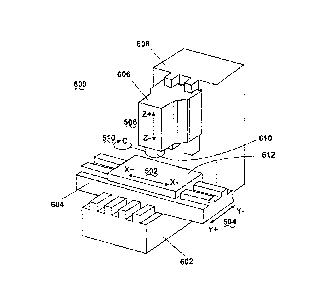
[0066] Embodiments of the apparatus. FIG. 17 is a perspective view of a non-
spindle
machining apparatus in accordance with the "3-axis" and "4-axis" embodiments
of the
present invention. The apparatus employing the non-spindle multi-axis
machining
19
CA 02895007 2015-06-19
method of the present invention can be embodied in a variety of
configurations. In
contrast to that shown in FIG. 17, these embodiments are comparable to those
of
computer numerical controlled mills (known in the trade as "machining
centers"), except
that the present invention does not use a spindle to rotate a cutting tool.
Instead, as seen
in FIG. 9, a non-rotating cutting tool is used in accordance with various
embodiments of
the present invention. In this illustration a tool holder 610 replaces the
spindle into which
a non-rotating cutting tool 400 is affixed. The simplest embodiment of the
present
invention is a "3-axis" machine 600, which can drive the cutting tool along
any one of the
three linear axes (commonly known as the X-, Y-, and Z-axes) 502 504 506, or
any
combination of them (under certain circumstances), that together define the
machine's
three-dimensional work envelope. FIG. 15 illustrates a workpiece where a "3-
axis"
machine is sufficient to machine the circular cavity 508 into the workpiece
500 by means
of the process flowcharted in FIG. 18 described hereinafter. Yet another basic
embodiment is a "4-axis" machine 600, which has all of the three-axis linear
motion of
the "3-axis" machine plus a "rotary axis" 510 to continuously re-orient the
cutting tool's
face 404 in any direction to maintain its perpendicularity to a level two-
dimensional
cutting path. Maintaining perpendicularity optimizes the performance of the
cutting tool
and thus maximizes the range of shapes the machine can cut. The mechanism for
this
fourth axis 510 can be either a rotary-axis tool holder 610 to which the
cutting tool 400 is
attached or a rotary-axis table 612 to which the workpiece 500 is attached. By
either
means, a "4-axis" machine is sufficient to machine the curved circular cavity
512 into the
workpiece 500 illustrated in FIG. 16 by means of the process flowcharted in
FIG. 19
described hereinafter.
[0067] FIG. 18 is a flow chart of the non-spindle machining method of the
present invention in
which it is machining the part depicted in FIG. 15 in accordance with the "3-
axis-
embodiment of the present invention. The non-spindle machining method 700
includes
the steps of setting up the machine for operation 701. A cutting tool is
fixtured in a tool
holder 703 and a workpiece is fixtured on a table 705. Tool and cutting path
data is then
loaded into the machine's controller 707 and a cycle start is initiated to
execute operation
709. The tool then moves toward the workpiece to the start point of the first
cutting path
711 and then removes material from the workpiece along a cutting path without
spindle
CA 02895007 2015-06-19
rotation 713. At the end point of the cutting path the tool moves to a relief
point above
the workpiece 715 and a determination is made if the operation is completed
717. If not,
the operation continues with the cutting tool moving to the start point of the
next cutting
path 711. If the operation is completed, the cutting tool returns to the cycle
start position
719 and the operation ends 721.
[0068] FIG. 19 is a flow chart of the non-spindle machining method of the
present invention in
which it is machining the part depicted in FIG. 16 in accordance with the "4-
axis"
embodiment of the present invention. The method 800 includes the steps of
setting up
the machine for operation 801 where the cutting tool is fixtured in a tool
holder 803. A
workpiece is then fixed on the table 805 and the tool and cutting path data is
loaded into
the controller 807. Cycle start is initiated 809 and the cutting tool moves
toward the
workpiece to the start part of the first cutting path 811. The cutting tool
then removes
material from the workpiece along a level 2-dimensional cutting path without
spindle
rotation while the tool holder continuously re-orients the tool to maintain
the
perpendicularity of the face of the cutting edge to the cutting path 813. At
the end point
of the cutting path the tool moves to a relief point above the workpiece 815.
A
determination is then made if the operation is completed 817. If not, the
cutting tool
moves to the start point of the next cutting path 811. If the operation is
completed, then
the cutting tool returns to the cycle start position 819 and the operation
ends 821.
[0069] Still more complex embodiments are the "5-axis" and the "7-axis"
machines. These
embodiments have all of the three-axis linear and fourth-axis rotary motions
of the "4-
axis" machine plus additional rotary or tilt axes to orient the cutting tool's
face in any
direction to maintain its perpendicularity to any three-dimensional cutting
path. These
machines are unrestricted in the shapes and surfaces they can produce,
including NURBS
surfaces, by means of the process flowcharted in FIG. 20.
[0070] Flow chart of the method. FIG. 20 is a flow chart of the non-spindle
machining method
in accordance with a "5-axis" or "7-axis" embodiment of the present invention.
The
process 900 includes the step of setting up the machine for operation 901 and
flxturing
the cutting tool in a tool holder 903. The workpiece is fixtured on the table
905 and the
tool and cutting path is loaded into the controller 907. Cycle start is
initiated 909 and the
cutting tool moves to the start point of the first cutting path 911. The
cutting tool then
21
CA 02895007 2015-06-19
removes material from the workpiece along a 3-dimensional cutting path without
spindle
rotation while the tool holder continuously re-orients and tilts the tool to
maintain the
perpendicularity of the face of the cutting edge to the cutting path 913. A
determination
is made if the operation is completed 917. If not completed, the cutting tool
moves to the
start point of the next cutting path 911 and the operation continues. If the
operation is
complete, the cutting tool returns to the cycle start position 919 and the
operation ends
921. Thus, the method of the present invention as described in FIGs. 18-20,
overcome
the limitations of lathes and mills in profiling operations by employing a non-
spindle
method of machining and eliminates milling for most profiling operations.
[0071] In still another embodiment, FIG. 22 illustrates a non-spindle vertical
machining center
using one or more linear drive motors 2200 capable for achieving controlled
fracturing
machining of workpiece materials. The non-spindle vertical machining center
2200
includes a base 2201 that provides support for a work table 2203 which asked
to hold a
workpiece 2205 into a fixed position. Those skilled in the art will recognize
that the work
table 2203 may include one or more clamps, fasteners and/or a vice for holding
the
workpiece 2205 still in relation to the table 2203 during machining
operations. Affixed
atop the base 2201 is a flying bridge 2207 moves along an X-axis by the use of
one or
more linear drives 2208 positioned within the base 2201. Those skilled in the
art will
recognize that various combinations of both linear and rotary drives may also
be used to
control movement of the work table 2203 and flying bridge 2207. Moreover, the
term
"linear drive" encompasses chains, belts, ball screws, hydraulic and pneumatic
cylinders,
and electric linear motors.
[0072] The flying bridge 2207 is a substantially U-shaped member or tower and
is manufactured
to bear substantially large amounts of upward and downward force when cutting
the
workpiece using the controlled fracturing process. The linear drive operates
by moving
the bridge 2207 along a channel or track 2213 positioned within and at an
outside edge of
the base 2201. A cutting tool 2211 as described herein, is generally fixed in
position,
with regard to the flying bridge 2207, and uses a tool holder assembly 2209 to
hold the
cutting tool's face into a fixed position. Those skilled in the art will
recognize that an
electric motor can produce either rotary or linear motion depending on its
configuration.
An electric linear motor can be used as a linear drive for embodiments of the
present
22
CA 02895007 2015-06-19
invention. The linear drive works in a manner to propel and/or move a cutting
tool 2211
along a cutting path with a force that is sufficient to induce controlled
fracturing of the
workpiece to remove material.
[0073] In order to freely move the table 2203 in both the Y-axis and Z-axis,
one or more linear
drives 2215 are used within the base 2201. Those skilled in the art will
recognize that
only linear motion (by means of linear drives of any type) are used herein
without
rotation of either the cutter or the workpiece about a spindle. The machine
described
herein uses linear motion solely to produce sufficient force to remove
material from a
workpiece along a multi-dimensional cutting path, unlike prior art machine
tools that also
require torque from a spindle to produce that force. This distinguishes the
present
invention from prior art spindle machine tools such as mills and lathes. Also,
the
machine as describe herein can do so along a 3-dimensional cutting path,
unlike the
restriction to a 1-dimensional cutting path of prior art non-spindle machine
tools. This
distinguishes the present invention from prior art non-spindle machine tools
such as
broachers, planers, and shapers.
[0074] In one embodiment, the base 2201 includes a void and/or cavity therein
for allowing the
linear drive(s) 2215 to move in Y and Z directions. The linear drives 2215
typically
move along a shaft, rod and/or screw assembly 2217 solely in a linear or
straight line
motion at cutting speeds sufficient to achieve controlled fracturing as
defined herein. No
rotation about a spindle is used for either the cutting tool or the workpiece.
Upper
portions of the base 2201 can be removed for enabling the table 2203 to move
freely. As
seen in FIG. 22, this occurs by allowing the linear drive 2215 to move the
work table
2203 in either a Y-axis and/or Z-axis for enabling the workpiece 2205 to
remain in
contact with the cutting tool 2211. As described herein, precision movements
of the
various linear drives 2208, 2215 etc. is accomplished though a microprocessor
2219
running software programming for creating predetermined cuts and shapes of the
workpiece 2205. Although the linear drive 2215 is shown as a single unit for
controlling
motion of the work table 2203, it should be evident to those skilled in the
art the a
plurality of linear drive motors can be used in various configurations to
achieve precision
movement at speeds to induce controlled fracturing machining.
23
CA 02895007 2015-06-19
[0075] FIG. 23 and FIG. 24 are side views showing movement of the table in the
Z-axis. FIG.
23 illustrates a non-spindle vertical machine center 2300 where a workpiece
2301 is fixed
on top of a table 2303. The flying bridge 2305 is positioned above the
workpiece 2301
where a cutting tool 2307 moves linearly, without rotation of either the tool
or the
workpiece, to achieve material removal of the workpiece 2301 by a controlled
fracturing
process as described herein. In FIG. 23 a linear drive 2309 positions a shaft
2311 in a
manner such that the cutting tool 2307 is not yet in contact with the
workpiece 2303. As
seen in FIG. 24, the non-spindle vertical machining center 2400 is shown where
the work
table 2401 is moved vertically on the Z-axis by enabling the linear drive 2403
to move
the shaft 2405 vertically so the workpiece 2407 is in contact with the cutting
tool 2409.
[0076] FIG. 25 and 26 illustrate side views showing movement of the flying
bridge in the X-
axis. The non-spindle vertical machining center 2500 is shown where the work
table sits
atop the base 2501. The workpiece 2505 is on the worktable 2505 and positioned
adjacent to the flying bridge 2507. As described herein, the flying bridge
2507 uses one
or more linear drives 2509 to move the cutting tool 2508 to the workpiece
2509. The
linear drive 2509 moves along a rod or track 2511 to position the cutting tool
at a precise
location in relation to the work piece 2505. FIG. 26 illustrates the non-
spindle vertical
machining center 2600 where the flying bridge 2603 has moved using the linear
drive
2606 into a position such that the cutting tool 2607 is operatively engaged
and/or
touching with the workpiece 2605. Additionally, the work table 2609 has been
moved
vertically on the Z-axis using linear drive 2610 so that the workpiece 2609
can be
accessed by the flying bridge 2603 and cutting tool 2607.
[0077] FIG.27 is a block diagram illustrating the microprocessor control of
one or more linear
drives used in the non-spindle vertical machining center. The control system
2700
utilizes one or more microprocessors 2707 to control the linear drives 2701,
2703, 2705
used for controlling motion of the flying bridge and work table in the X-, Y-,
and Z-axis.
Those skilled in the art will recognize that since X-, Y-, and Z-axis can be
independently
controlled, 5-axis or 7-axis movement of the machining tool is possible to
achieve the
necessary curved or arced cutting of the tool path. A keyboard 2709 or other
input device
can be used by the user to control and/or enter programming code for governing
the
precision movement of the non-spindle vertical machining center.
24
CA 02895007 2015-06-19
[0078] Thus, the present invention is directed to a base section to which
other machining
components are attached directly or by intermediary devices and includes one
or more
linear drives. One or more cutting tools are affixed to at least one linear
drive where the
at least one drive moves the cutting tool with sufficient force to induce
controlled
fracturing. A work table affixed to the base for holding a workpiece in a
fixed position in
relation to the at least one table such that the at least one table moves
independently of
the cutting tool. A programmable controller is further configured to cause a
cutting edge
of the cutting tool to be in operative engagement with a workpiece. The
workpiece is
held by the table in order to cause the cutting edge to translate along the
accurate path for
cutting the workpiece. In use, the cutting tool is not rotated by a spindle as
in milling nor
is the workpiece that is held by the table, rotated by a spindle - as in
turning processes.
The cutting tool and the table move relative to one another along any three-
dimensional
path within a work envelope of the machining apparatus for profiling the
workpiece into
a predetermined shape.
[0079] While the present invention has been described in terms of the
preferred embodiments
discussed in the above specification, it will be understood by one skilled in
the art that the
present invention is not limited to these particular preferred embodiments,
but includes
any and all such modifications that are within the spirit and scope of the
present invention
as defined in the appended claims.