Note: Descriptions are shown in the official language in which they were submitted.
CA 02895011 2015-06-18
1
SYSTEM FOR CLEANING THE BURNER AND CONFINING FUEL IN SOLID-FUEL
BOILERS
DESCRIPTION
Object of the invention
The object of the invention, in general, falls within the industrial sector of
solid-fuel boilers
and, in particular, refers to a system for
a) cleaning all or part of the surface of the burner plate, removing the
remains of
ashes that accumulate in it; performing this total or partial cleaning with no
need to
disassemble the burner or stop the operation of the boiler; and
b) confining the solid fuel in the burner so that the plate accepts a larger
amount of
fuel without varying its size.
Background of the invention
In the current state of the art boilers using solid fuels are already known,
and in particular,
boilers that use solid fuels of small size such as chips, olive stones and, in
general, small
cylinders of compacted biomass, known generically as "pellets".
The use of these fuels, due to their compact constitution and their reduced
size, is
advantageous as compared to certain other solid fuels of larger size, allowing
the
automation of the supply to the biomass boilers from a storage silo.
Also known are biomass boilers that use "pellets" as fuel and incorporate a
system for
cleaning the ashes that accumulate in the burner. For example, and among
others, in
documents CH182329, US4437452 and EP2039993 boilers of this type are
described.
Unresolved problems in these types of boilers are those relating to the
cleaning of the
ashes in the burner plate when cleaning is required, not only of the edge, but
also of all or
most of the burner plate to prevent the ashes from becoming embedded and they
accumulate in the burner affecting the performance of the boiler negatively.
CA 02895011 2015-06-18
2
Moreover, the power of the boiler is a direct function of the quantity of
solid fuel that the
burner accepts. In any of the currently known solutions, the quantity of solid
fuel that the
burner accepts is determined by its own dimensions. To increase the power of
the boiler,
very large plates are needed.
Description of the invention
The object of the invention is a system for cleaning at will all or part of
the surface of the
burner and confining the solid fuel in the burner in such a way that the plate
accepts a
larger quantity of fuel without varying its size. The solid-fuel boiler is of
the type that
consist of a burner plate associated with a combustion chamber; a supply
device that
supplies the solid fuel from a storage hopper to the centre of the plate
through an intake
line using controlled/automated dosing; and an ash discharging device
associated with a
collector on which said ashes overflow from the perimeter of the plate. It is
characterized
in that the plate is mobile and has means for rotating with respect to the
supply device
and/or the ash-discharging device; and the ash-discharging device is fixed and
has at
least one blade with means to guide it at will on the plate.
In the joint action of the mobile plate and fixed ash discharging device,
starting from a
tangential position in which its blades are arranged on the perimeter of the
plate, the
ashes deposited can be cleaned by sweeping; they occupy a crown of any width
between
a minimum (corresponding with the blades positioned very near the edge of the
plate) and
a maximum (corresponding with the blades positioned occupying the full width
of the
plate).
It is also characterized in that the blades of the ash discharging device are
increased in
height, all of them delimiting (in conjunction with the plate and in a
tangential position in
which they act as side slats) a perimetrally closed container to confine the
solid fuel; so
that the plate accepts a larger quantity of fuel without varying its size.
Other configurations and advantages of the invention can be deduced from the
following
description, and from the dependent claims.
Description of the drawings
CA 02895011 2015-06-18
3
To understand the object of the invention better, a preferential form of
embodiment is
represented in the attached figures, subject to accessory changes that do not
essentially
alter it. In this case:
Figure 1 represents a general view in perspective of a burner equipped with
the ash
discharging device (3) used to clean all or part of the surface of the plate
(1) according to
the invention, in which the movement of the blades has been schematized (31).
Figure 2a represents an upper perspective view corresponding to the foregoing
figure and
with the blades (31) in a starting position, before starting the cleaning of
the plate (1).
Figures 2b and 2c each represent upper perspective views similar to figure 2a,
for
respective positions in which the blades (31) clean by sweeping a crown (C) of
any width
(figure 2b) and a maximum crown (Cm) (figure2c).
Figure 3 represents a general cross-section according to indication A:A of
figure 2c.
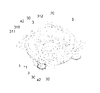
Figure 4 represents a general view in perspective similar to figure 1 for an
alternative
embodiment, in which the blades (31) are increased in height and each of the
blades
(311), (312) appear from a central head (310).
Figures 5a, 5b and 5c each represent similar upper perspective views,
respectively, of
figures 2a, 2b, 2c for the embodiment of figure 4.
Figure 6 represents a cross-section in detail according to indication E: E of
figure 5c.
Figure 7 represents a section in detail, according to indication D: D of
figure 5c.
Preferential embodiment of the invention
The following describes an example of practical, non-limiting embodiment of
this
invention. Other modes of embodiment in which accessory changes are introduced
that
do not essentially change it are not ruled out.
In the drawings of this example of preferential embodiment, the following
references and
particularities have been indicated:
1.- burner plate
CA 02895011 2015-06-18
4
el .- theoretical axis of the plate
2.- solid fuel supply device
20.- intake line
21.- endless helix/screw
3.- ash-discharging device
30.- physical axis
31.- cleaning blades
310.- head of the blades
311.- wings of the blades
e2.- theoretical axis of the blades
32.- pinion
The object of the invention is a system for cleaning the burner and confining
fuel in solid-
fuel boilers of the type that use solid fuels such as chips, olive stones and,
in general,
small cylinders of compact biomass known generically as "pellets".
In a known way, these boilers consist of a plate (1) of the burner associated
with the
combustion chamber; a supply device (2) that supplies the solid fuel from a
storage
hopper using controlled/automated dosing; and an ash-discharging device (3)
associated
with a collector on which said ashes overflow from the perimeter of the plate
(1).
The solid fuels used reach the burner (1) using, for example, a supply device
(2), of the
helix or endless screw type (21) that supplies them, at controlled speed, from
a storage
hopper, accessing a central zone of the plate (1) through an intake line (20).
Also in a known way, the ashes resulting from combustion are removed by
mechanical
means continuously or periodically.
CA 02895011 2015-06-18
In conformity with the invention and according to the embodiment represented,
the plate
(1) is mobile with respect to the supply device (2) and/or to the ash-
discharging device (3):
it rotates, or can rotate, on its theoretical central axis (el). See figure 3.
5 Any solution used to achieve the rotation of the plate (1) is indistinct,
and is included in the
object of the invention. In the example of embodiment represented, to achieve
the
rotation of the plate (1) a crown wheel (11) is arranged under it and
occupying its entire
perimeter; said crown wheel (11) engaging with one or several drive pinions
that are
operated by an external motor (neither the drive pinions nor the motor are
represented).
In conformity with the invention and according to the embodiment represented,
the ash-
discharging device (3) is fixed and consists of at least one blade, (31) with
means to guide
it at will on the plate (1). Each ash-discharging device (3) rotates or can
rotate on its
theoretical axis (e2). See figures 1 and 4.
Any solution used to achieve the rotation of the blades (31) is indistinct,
and is included in
the object of the invention. In the example of embodiment represented, to
achieve the
rotation of the blades (31) they are arranged jointly with a physical axis
(30), to which a
pinion (32) is also , arranged on a different plane. This pinion (32),
engaging with one or
several drive pinions (not represented), turns in one direction or the other,
moves with it in
its rotation on the physical axis (30) and causes the corresponding blade (31)
to tilt in one
direction or the other.
The blades (31) are arranged on the plate (1) and occupy its surface, starting
from a
tangential position, in which they occupy the perimetral zone of the plate (1)
¨see figures
2a and 5a- to a radial position, in which they occupy the entire width of the
plate (1) -see
figures 2c and 5c-.
Any geometry of the blades (31) is indistinct, and is included in the object
of the invention,
as well as any arrangement of the theoretical axis (e2) on which the blades
(31) rotate:
- in the example of embodiment represented in figures Ito 3 the blades
(31) present
planar configuration of low height and start radially from an end head and the
theoretical axis (e2) on which they rotate is arranged on said end head;
CA 02895011 2015-06-18
6
- in the example of embodiment represented in figures 4 and subsequent
figures,
the blades (31) present curved configuration and are increased in height. Each
blade (31) is structured on a central head (310) from which each of the curved
wings (311), (312) start radially and the theoretical axis (e2) on which they
rotate is
arrange on said end head. (310).
In a tangential starting position, represented in figures 2a and 5a, the
blades (31) are
arranged on the perimeter of the plate (1), without interfering its surface or
performing
cleaning.
To clean the plate (1), according to the system that is the object of the
invention, it is
caused to rotate; in this case counter-clockwise, so that the blades (31) are
arranged on
the surface of the plate (1) occupying a crown (C) of any width and clean by
sweeping the
ashes on the surface delimited by said crown (C).
Depending on the width of said crown (C) the swept surface will be larger or
smaller:
starting from an initial limit position ¨represented in figures 2a and 5a- the
blades (31)
rotate so that they can sweep a crown (C) -represented in figures 2b and 5b-
whose width
varies from a minimum width in initial limit position in which the end of the
blades (31) is
very near the edge of the plate (1) to a final limit position in which the end
of the blades
(31) is very near the centre of the plate (1) sweeping a maximum crown (Cm) -
represented
in figures 2c and 5c- which corresponds to the entire surface of the plate
(1).
In addition, and according to the example of embodiment represented in figure
4 and
subsequent figures, the blades (31) are increased in height and present
asymmetric
arrangement, defined by said central head (310) from which said curved wings
(311),
(312) start. In the initial position, corresponding to figure 5a, these blades
(31) as a group
define a wall that accompanies the plate (1) perimetrally and, being increased
in size,
delimit a perimetrally closed container to confine the solid fuel; so that the
plate (1)
accepts a larger quantity of fuel without varying its size.
From the basic concept described, any embodiments that do not essentially
alter, change
or modify the proposal are included in the object of the invention: For
example, the
number of blades (31) used is indistinct for the purposes of the invention
although, for
functionality, symmetry and ease of construction, in the examples of
embodiment
described four blades (31) have been represented.
CA 02895011 2015-06-18
7
The materials, dimensions, proportions and, in general, those other accessory
or
secondary details that do not essentially alter, change or modify the proposal
may be
variable.
The terms in which this report is written are a true reflection of the object
described, and
must be taken in their broadest sense and never in a limiting manner.