Note: Descriptions are shown in the official language in which they were submitted.
CA 02895161 2015-06-15
WO 2014/094070
PCT/AU2013/001512
1
TITLE=
SYSTEM AND METHOD FOR REFUELLING A COMPRESSED GAS
PRESSURE VESSEL USING A THERMALLY COUPLED NOZZLE
FIELD OF THE INVENTION
This invention relates generally to a compressed gas transfer
system. In particular, the invention relates to a compressed natural gas
(CNG) transfer system including a nozzle thermally coupled to and
optionally inside a CNG cylinder to reduce temperature rises in the
cylinder.
BACKGROUND OF THE INVENTION
Natural gas fuels are relatively environmentally friendly for use in
vehicles, and hence there is support by environmental groups and
governments for the use of natural gas fuels in vehicle applications.
Natural gas based fuels are commonly found in three forms: Compressed
Natural Gas (CNG), Liquefied Natural Gas (LNG) and a derivative of
natural gas called Liquefied Petroleum Gas (LPG).
Natural gas fuelled vehicles have impressive environmental
credentials as they generally emit very low levels of SO2 (sulphur dioxide),
soot and other particulate matter. Compared to gasoline and diesel
powered vehicles, CO2 (carbon dioxide) emissions of natural gas fuelled
vehicles are often low due to a more favourable carbon-hydrogen ratio
found in natural gas. Natural gas vehicles come in a variety of forms, from
small cars to buses and increasingly to trucks in a variety of sizes. Natural
gas fuels also provide engines with a longer service life and lower
maintenance costs. Further, CNG is the least expensive alternative fuel
when comparing equal amounts of fuel energy. Still further, natural gas
fuels can be combined with other fuels, such as diesel, to provide similar
benefits mentioned above.
A key factor limiting the use of natural gas in vehicles is the storage
of the natural gas fuel. In the case of CNG and LNG, the fuel tanks are
CA 02895161 2015-06-15
WO 2014/094070
PCT/AU2013/001512
2
generally expensive, large and cumbersome relative to tanks required for
conventional liquid fuels having equivalent energy content. In addition, the
relative lack of wide availability of CNG and LNG refuelling facilities, and
the cost of LNG, add further limitations on the use of natural gas as a
motor vehicle fuel. Further, in the case of LNG, the cost and complexity of
producing LNG and issues associated with storing .a cryogenic liquid on a
vehicle further limit the widespread adoption of this fuel.
While LNG has had some success as a liquid fuel replacement in
some regions of the world, the lack of availability of LNG and its high cost
means that in many regions of the world it is not a feasible alternative fuel.
In the case of CNG, it also has had some success as a liquid fuel
replacement but almost exclusively in spark ignition engines utilising low
pressure carburetted port injection induction technology. This application
is popular in government bus fleets around the world where the cleaner
burning natural fuel is used in a spark ignition engine fitted in place of a
conventional diesel engine.
Some of the above issues are also mitigated when using LPG, and
this fuel is widely used in high mileage motor cars such as taxis.
However, cost versus benefit comparisons are often not favourable in the
case of private motor cars. Issues associated with the size and shape of
the fuel tank, the cost variability of LPG and the sometimes limited supply
mean that LPG also has significant disadvantages that limit its widespread
adoption. In summary, unless there is massive investment in a network of
LNG plants around major transport hubs, CNG is the only feasible form of
natural gas that is likely to be widely utilised in the near future.
However, some technical problems still limit the efficiency of CNG
fuel systems. For example, the pressure to which composite CNG
cylinders can be filled at a typical CNG re-fuelling station is limited
because the heat of compression can cause overheating of cylinders
being filled. This has typically meant that a nominal 250 bar at 21 degrees
Celsius (settled temperature) is the limit for composite CNG cylinder
design, and has become the standard adopted in many parts of the world
CA 02895161 2015-06-15
WO 2014/094070
PCT/AU2013/001512
3
including the US.
In the US, codes typically allow for filling to an overpressure of 1.25
times the pressure rating of the CNG cylinder provided it would
subsequently settle to a nominal 250 bar if cooled to 21 deg. C. The code
. also identifies in-cylinder heating as having the potential to cause
transient
temperature excursions exceeding cylinder design parameters, and these
high temperatures also cause higher internal cylinder pressures such that
fills of between 70% and 80% of cylinder "name plate" ratings are often all
that can be achieved. This has a significant detrimental impact on the
range of CNG vehicles, and also on consumers who often have difficulty
understanding the variability of a CNG cylinder fill and the impacts on
vehicle range.
Also, the variability and inability to fully fill CNG cylinders has a
major impact on the use of CNG cylinders in bulk gas transport, where
poor CNG cylinder filling has significant commercial impact on the cost of
gas delivered.
For example, in Europe, the relevant codes limit the maximum
pressure in composite CNG cylinders during re-fuelling to 260 barg to
ensure maximum design temperatures are not exceeded. These
limitations meant that the currently available composite cylinders designed
for 350 barg operating pressure and above could not be utilised in
conventional CNG re-fuelling systems. Thus the opportunity to utilise
smaller CNG cylinders, or to achieve increases in vehicle range, or
improved commercial outcomes for gas transport, using the same size fuel
cylinders, can not be realised.
A further problem with current systems for fast refuelling of large
CNG vessels, such as used in buses and trucks, is that the size and
weight of the refuelling connection makes them difficult to handle and
problematic relative to the smaller connectors used commonly for filling
cars.
International Patent Application Publication, WO 2008/074075,
titled "A COMPRESSED GAS TRANSFER SYSTEM", disclosed for the
CA 02895161 2015-06-15
WO 2014/094070
PCT/AU2013/001512
4
first time a liquid backpressure system that enables the complete filling of
on-vehicle CNG fuel tanks at full pressures. However, with this system
the delivery of liquid into and out of CNG cylinders limits the application of
the technology, and can slow transfer rates due to limitations in the liquid
handling.
There is therefore a need for an improved system and method for
refuelling compressed gas pressure vessels.
OBJECT OF THE INVENTION
It is an object of some embodiments of the present invention to
provide consumers with improvements and advantages over the above
described prior art, and/or overcome and alleviate one or, more of the
above described disadvantages of the prior art, and/or provide a useful
commercial choice.
SUMMARY OF THE INVENTION
In one form, although not necessarily the only or broadest form, the
invention resides in a pressure vessel refuelling system comprising:
a pressure vessel having a first gas inlet/outlet port and an interior
cavity; and
a nozzle in fluid communication with the first gas inlet/outlet port;
wherein the nozzle and the pressure vessel are thermally coupled
such that Joule-Thomson expansion of a gas flowing through the nozzle
cools the interior cavity and contents of the pressure vessel.
Preferably, the nozzle is a convergent-divergent (CD) nozzle.
Preferably, the nozzle is positioned in the interior cavity of the
pressure vessel.
,Preferably, the nozzle is positioned in the interior cavity of the
pressure vessel and spaced away from the first gas inlet/outlet port.
Preferably, the nozzle is positioned outside the interior cavity of the
pressure vessel and adjacent the first gas inlet/outlet port.
Preferably, the pressure vessel is a compressed natural gas (CNG)
CA 02895161 2015-06-15
WO 2014/094070
PCT/AU2013/001512
vessel.
Preferably, the inlet pressure to the nozzle is maintained at a
continuous high pressure to increase Joule-Thomson cooling.
Preferably, the nozzle maintains a relatively continuous high flow
5 throughout a vessel refilling cycle
Preferably, the pressure vessel is one of a plurality of pressure
vessels used for the storage or transport of compressed natural gas
(CNG).
Preferably, the pressure vessel further comprises a secondary gas
outlet port in fluid communication with a gas delivery line in fluid
communication with the first gas inlet/outlet port, whereby a portion of gas
in the refuelling system traverses a cooling cycle loop, cooling the interior
cavity and contents of the pressure vessel.
Preferably, the cooling cycle loop includes a gas chiller.
Preferably, the cooling cycle loop includes a secondary gas
compressor.
Preferably, the cooling cycle loop includes a flow control valve in
fluid communication with the secondary gas outlet port, whereby a gas
recycle rate through the pressure vessel is controlled.
Preferably, the cooling cycle loop includes a recirculation
compressor in fluid communication with the secondary gas outlet port,
whereby a gas recycle rate through the pressure vessel is controlled.
BRIEF DESCRIPTION OF THE DRAWINGS
To assist in understanding the invention and to enable a person
skilled in the art to put the invention into practical effect, preferred
embodiments of the invention are described below by way of example only
with reference to the accompanying drawings, in which:
FIG. 1 illustrates a pressure vessel refuelling system that supplies
gas at high pressure to a gas dispenser, which then supplies the gas to
CNG fuel tanks, according to an embodiment of the present invention.
FIG. 2 is a graph illustrating an example of mass flow rate vs. time
CA 02895161 2015-06-15
WO 2014/094070
PCT/AU2013/001512
6
of CNG gas into a typical CNG storage vessel, such as a CNG vehicle fuel
tank, according to an embodiment of the present invention.
FIG. 3 illustrates a pressure vessel refuelling system, including a
cooling cycle loop, which supplies gas at high pressure to CNG transport
or storage cylinders according to an embodiment of the present invention.
Those skilled in the art will appreciate that minor deviations from
the layout of components as illustrated in the drawings will not detract
from the proper functioning of the disclosed embodiments of the present
invention.
DETAILED DESCRIPTION OF THE PREFERRED EMBODIMENT
Embodiments of the present invention comprise systems and
methods for refuelling compressed gas pressure vessels using a thermally
coupled nozzle. Elements of the invention are illustrated in concise outline
form in the drawings, showing only those specific details that are
necessary to the understanding of the embodiments of the present
invention, but so as not to clutter the disclosure with excessive detail that
will be obvious to those of ordinary skill in the art in light of the present
description.
In this patent specification, adjectives such as first and second, left
and right, front and back, top and bottom, etc., are used solely to define
one element or method step from another element or method step without
necessarily requiring a specific relative position or sequence that is
described by the adjectives. Words such as "comprises" or "includes" are
not used to define an exclusive set of elements or method steps. Rather,
such words merely define a minimum set of elements or method steps
included in a particular embodiment of the present invention.
According to one aspect, the invention includes a pressure vessel
refuelling system. The system includes a pressure vessel having a first
gas inlet/outlet port and an interior cavity. A nozzle is
in fluid
communication with the first gas inlet/outlet port. The nozzle and the
, pressure vessel are thermally coupled such that Joule-Thomson
CA 02895161 2015-06-15
WO 2014/094070
PCT/AU2013/001512
7
expansion of a gas flowing through the nozzle cools the interior cavity of
the pressure vessel.
Advantages of the present invention include enabling improved fast
fill refuelling of CNG fuel tanks by reducing the in-tank temperature rise
caused by the heat of compression as gas is added to a tank. Further, the
use of a nozzle inside or adjacent a fuel tank enables faster mass flow
rates of gas into the tank during refuelling. Also, according to some
embodiments, by re-cycling a portion of gas out of a tank during refuelling
and back to a gas chiller, further cooling of a tank is achieved. That
enables a tank to be quickly filled to its capacity pressure rating at a non-
elevated operating temperature such as 21 degrees C, eliminating the
"partial fill" result of prior art processes for refuelling CNG tanks caused
by
the heat of compression significantly raising tank temperatures. Further,
by connecting high pressure supply lines from a supply source directly to
an interior of a tank being refuelled, smaller diameter supply lines can be
employed, enabling reduced-size CNG couplings. Also, frictional energy
losses in the supply hoses are reduced, because gas in a high pressure
line will travel at a slower velocity to achieve an equivalent mass flow rate
of corresponding low pressure line. Further this leads to the potential to
fast fill vehicles with large CNG vessels, such as buses and trucks, using
the standard consumer friendly nozzles used for CNG car refuelling.
Further holding the gas at consistent pressure up to the vessel, through
the chilling system, enables chilling of the gas with an economic heat
exchanger. The density of the gas remains high and the velocity
consistent and optimal through the heat exchanger, thus facilitating good
heat exchange performance per unit surface area.
. In this specification CNG cylinders that supply or store gaseous
fuel
are synonymously referred to as tanks, vessels, pressure vessels, CNG
cylinders and cylinders.
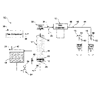
FIG. 1 illustrates a pressure vessel refuelling system 10 that
supplies gas at high pressure to a gas dispenser 12, which then supplies
the gas to CNG fuel tanks 13, 15, according to an embodiment of the
CA 02895161 2015-06-15
WO 2014/094070
PCT/AU2013/001512
8
present invention. The system 10 includes a CNG primary storage vessel
14 that is partially filled with natural gas 16 and partially filled with an
aqueous liquid 18. A thin layer of a second liquid in the form of an oil 20
floats on top of the aqueous liquid 18. Because the oil 20 is both
immiscible with the aqueous liquid 18 and is less dense than the aqueous
liquid 18, the layer of oil 20 functions as a "liquid piston" that moves up
and down inside the vessel 14 as a volume of the aqueous liquid 18 in the
vessel 14 changes.
The floating layer of oil 20 creates a barrier that prevents the
aqueous liquid 18 from contacting and evaporating into the natural gas 16.
In some cases the oil 20 may become saturated with the natural gas 16.
However, because the oil 20 does not leave the storage vessel 14, and
because only a thin layer of oil 20 is required (which becomes saturated
with natural gas on initial fill), only insignificant natural gas 16 is not
available, or is lost from storage.
The system 10 further includes a liquid storage tank 22 and a pump
24. In use, for example when a CNG vehicle or a plurality of CNG
vehicles are being refuelled from the gas dispenser 12, the pump 24
pumps the aqueous liquid 18 through a check valve 26 and through a
lower float valve 28 in a lower inlet/outlet port and into the vessel 14.
Simultaneously, the natural gas 16 flows through an upper float valve 30
in an upper inlet/outlet port, through a gas chiller 32 and to the dispenser
12.
The lower float valve 28 functions to prevent the gas 16 from exiting
through the bottom of the vessel 14 in the event that all of the aqueous
liquid 18 is drained from the vessel 14. Similarly, the upper float valve 30
functions to prevent the aqueous liquid 18 from exiting through the top of
the vessel 14 in the event that all of the gas 16 is pushed out of the vessel
14 by the layer of oil 20 rising to the top of the vessel 14. As an example,
the lower float valve 28 and the upper float valve 30 can function as
described in international patent application no. PCT/AU2012/000265,
titled Compressed Natural Gas Tank Float Valve System and Method
CA 02895161 2015-06-15
WO 2014/094070
PCT/AU2013/001512
9
published on 20 September 2012 under International Publication No.
, W02012/122599, the contents of which are hereby incorporated in their
entirety.
During the refuelling process, for example of a vehicle fuel tank
connected to the dispenser 12, a coalescer filter 34 functions as a filter to
remove traces of the oil 20 from the gas 16 before such traces reach the
dispenser 12. It is normal in the CNG industry to use such filtration
methods to remove trace compressor oil. However,
unlike in a
compressor, the oil-gas interface is essentially static'and does not entrain
oil in the gas. Thus the layer of oil 20 enables a significantly more
efficient
gas transfer system, even though traces of the oil 20 may require filtering
by the coalescer filter 34. It is noted as industry normal for a small amount
of compressor oil to carry over with the compressed gas. Thus managing
oil carry over from the storage is seen as little different to managing
conventional oil carry over with gas from the gas compressors.
When re-filling the CNG storage vessel 14 with natural gas 16, or
while re-fuelling a vehicle using the dispenser 12, a gas compressor 36
can be activated to allow the gas 16 to be compressed and supplied via a
check valve 38 from a natural gas supply line (not shown) either into the
storage vessel 14 or directly to the dispenser 12.
A pressure controller 39 enables the pump 24 to be activated
automatically when a pressure drop is detected in the storage vessel 14.
Working simultaneously with the gas compressor 36, the pump 24 enables
a high flow rate of gas to be delivered to the dispenser 12; that in turn
enables, for example, multiple CNG fuel tanks/vehicles to be refuelled
simultaneously from the dispenser 12 or a plurality of dispensers.
By displacing the already compressed natural gas 16 from storage
14 at constant high pressure to the dispenser 12, the steady state power
needed by the system 10 to maintain a constant maximum output of gas
16 from the dispenser 12 can be reduced by up to an order of magnitude
when compared to using online CNG compression to meet the required
delivery rate, from conventional industrial natural gas supply pressures.
CA 02895161 2015-06-15
WO 2014/094070
PCT/AU2013/001512
That means, for example, when refuelling several CNG vehicles
simultaneously from the dispenser 12, the compressor 36 can be much
smaller than would be required in a comparable refuelling system that did
not maintain or use a CNG storage vessel at a constant Pressure using
5 liquid
displacement of the stored gas. According to the present invention
the full amount of stored gas is available and deliverable at several times
the rate that would otherwise be possible using the equivalent power
applied only to a gas compressor.
The constant pressure from the supply system maximises the
10 Joule-Thomson cooling effect available at the cylinder nozzles 50, 52.
During refilling of the vessel 14 with the gas 16, as the gas 16 is
compressed into the vessel 14, the layer of oil 20 applies pressure to the
aqueous liquid 18 and opens a back pressure valve 40. The aqueous
liquid 18 then flows through the back pressure valve 40 and back into the
liquid storage tank 22. As the liquid level rises in the storage tank 22, air
in the tank 22 is vented to atmosphere through a vapour vent 42.
During a refuelling process, CNG gas exits the dispenser 12 while
still at a storage pressure such as 6000 psig and is directed into the CNG
fuel tanks 13, 15 via high pressure lines 44. Those skilled in the art will
appreciate that various standard connectors, bleed valves, etc. are
ordinarily included at an interface 46 between an output line 48 of the
dispenser 12 and the supply lines 44. The storage pressure is maintained
until the gas flow reaches a nozzle 50, 52 inside the fuel tanks 13, 15,
respectively.
When refuelling begins of an empty fuel tank 13, 15, the pressure
differential between the high pressure supply lines 44 upstream of the
nozzles 50, 52 and the inside cavities of the fuel tanks 13, 15 is generally
greatest because the tanks 13, 15 may be nearly empty. As understood
by those skilled in the art, and following basic fluid dynamics principles
concerning nozzles, supersonic flow therefore will be initiated through the
nozzles 50, 52, causing gas flow in the nozzles 50, 52 to be "choked".
Because the supersonic flow near a throat of the nozzles 50, 52 prevents
CA 02895161 2015-06-15
WO 2014/094070
PCT/AU2013/001512
11
pressure waves from travelling upstream of the nozzles 50, 52, the mass
flow rate through the nozzles 50, 52 is generally unaffected by changes in
downstream pressure, even as the pressure in the fuel tanks 13, 15
steadily increases.
Further, Joule-Thomson expansion of the gas across the nozzles
50, 52, causes the gas entering the tanks 13, 15 to substantially cool.
However, simultaneously the heat of compression of the gas already
inside the fuel tanks 13, 15 tends to cause the gas temperature to.
increase. The result, according to embodiments of the present invention,
is that an overall temperature rise of gas in the tanks 13, 15 during the
refuelling process is substantially moderated compared to the prior art.
Initial cooling of the gas at the gas chiller 32 further assists in decreasing
the temperature rise of the gas during the refuelling process.
The nozzles 50, 52 can be of various designs, including for
example conventional convergent-divergent (CD) nozzles. Alternatively,
each nozzle 50, 52 can be replaced by a simple orifice. If the orifices are
adequately small, pressure inside the high pressure supply lines 44 can
be maintained at or near the storage pressure, such as 5000 psig, and
thus most Joule-Thomson expansion and the associated Joule-Thomson
cooling of the supplied gas will occur inside the fuel tanks 13, 15 and not
in the high pressure supply lines 44.
The nozzles 50, 52 are positioned inside the tanks 13, 15 and away
from inlet/outlet ports 54, 56 and away from the interior surfaces of the
tanks 13, 15. That prevents localised intense cooling from Joule-Thomson
expansion of the gas severely cooling and possibly compromising the
structural integrity of sides of the tanks 13, 15. Any ice or hydrates that
form on the divergent section of the nozzles 50, 52 is simply blown off the
nozzles 50, 52 by the gas flow and falls/vaporises in the interior cavity of
the tanks 13, 15.
According to other alternative embodiments of the present
invention, the nozzles 50, 52 can be positioned outside of and adjacent to
the tanks 13, 15, and thus immediately upstream of the inlet/outlet ports
CA 02895161 2015-06-15
WO 2014/094070
PCT/AU2013/001512
12
54, 56. If the high pressure supply lines 44 and the nozzles 50, 52 are
thermally insulated from the outside environment, the nozzles 50, 52 still
can be adequately thermally coupled to the tanks 13, 15. Joule-Thomson
expansion of the gas across the nozzles 50, 52 will thus still cool the
interior of the tanks 50, 52 during refuelling.
FIG. 2 is a graph illustrating an example of mass flow rate (kg/min)
vs. time (min) and the corresponding accumulated mass (kg) vs. time of
CNG gas into a typical CNG storage vessel, such as a CNG fuel tank 13,
15, during a refuelling process according to an embodiment of the present
invention. The line labelled "Orifice Rate" illustrates the gas mass flow
rate into the vessel during a refuelling process when an orifice is
positioned inside the vessel at the end of a high pressure supply hose.
The line labelled "Nozzle Rate" illustrates the gas mass flow rate into the
same vessel during a similar refuelling process when a CD nozzle is
positioned inside the vessel at the end of a high pressure supply hose.
The lines labelled "Orifice Total" and "Nozzle Total" refer to the total
accumulated mass stored in the vessel during the refuelling process
using, respectively, an orifice and a nozzle at the end of the gas supply
hose.
The vessel used to collect the data for FIG. 2 was a 300 litre type
IV (polymer-lined, composite overwrapped) pressure vessel, initial
pressure in the vessel for both the orifice and the nozzle fill was
approximately one atmosphere at room temperature, and a 3/8 inch
supply line operating at a constant pressure of approximately 6000 psig
delivered the gas to the vessel.
- As
shown, the orifice delivers a reasonably steady mass flow rate
of about 7-8 kg/min. of gas for the first six minutes of refuelling. However,
as the pressure in the tank increases, and accordingly the differential
pressure across the orifice decreases, the mass flow rate also steadily
decreases during the period of six minutes to '12 minutes from the start of
refuelling.
However, as shown, the nozzle delivers significantly better
CA 02895161 2015-06-15
WO 2014/094070
PCT/AU2013/001512
13
performance. The mass flow rate at the beginning of refuelling is slightly
better than with an orifice, and remains steady for, about the first seven
minutes of refuelling. Because the mass flow rate of a choked gas flow
through a nozzle is generally unaffected by downstream pressure
changes, the increasing pressure in the tank during refuelling does not
slow the mass flow rate into the tank.
After about seven minutes of refuelling, the mass flow rate through
the nozzle drops precipitously. That is because as the tank becomes full
the tank pressure approaches the supply line pressure, and the pressure
differential across the nozzle thus drops and causes gas flow through the
nozzle to become sub-sonic and thus "non-choked". Using a nozzle the
vessel is substantially full in seven minutes; whereas using an orifice the
vessel requires about 12 minutes to fill.
As shown, a nozzle can deliver an equivalent amount of gas mass
into a vessel in less time than can be delivered using a simple orifice.
Thus the use of a nozzle according to the teachings of the present
invention can further reduce the time required to refuel a vessel such as
the CNG fuel tanks 13, 15.. The nozzle used in the above example
demonstrates approximately a 30% reduction in refuelling time relative to
a simple orifice by elimination of the long conventional CNG top off tail.
The nozzle design can be optimised to vary flow rate and steepness of
drop off characteristics.
Additionally, it is noted that the constant flow rate provided by
nozzles can simplify the control in transferring CNG at a high transfer rate,
relative to simple orifice designs, where, for example, oversized orifices
may be used and additional cylinders sequenced to maintain a high
fuelling rate as the flow drops through the orifice ¨ no sequencing is
required to maintain flow rate with nozzles as the flow remains nearly
constant throughout the fill by the nozzle.
FIG. 3 illustrates a pressure vessel refuelling system 60, including a
cooling cycle loop, which supplies gas at high pressure to CNG transport
tanks 62, 64, according to an embodiment of the present invention.
CA 02895161 2015-06-15
WO 2014/094070 PCT/AU2013/001512
14
Natural gas enters the system 60 via a supply line 66 at a pipeline supply
pressure, such as 15-500 psig. The gas then enters a primary gas
compressor 68 where it is compressed to a buffer storage pressure such
as 3600 psig. A supply line 70 is connected to an output of the primary
gas compressor 68 and includes a check valve 72. The supply line 70
supplies gas to both a CNG buffer storage vessel 74 and to a secondary
gas compressor 76, which has a higher flow capacity than the primary gas
compressor 68. A supply line 78 is connected to an output of the
secondary gas compressor 76 and is at a final supply pressure, such as
6000 psig.
Similar to the pressure vessel refuelling system 10 described
above, in the system 60 a gas chiller 80 is used to pre-cool the gas before
delivery to the tanks 62, 62. Downstream Of the gas chiller 80, a gas
coalescer 82 is used to remove excess aerosols from the gas, which are
then removed through a condensate drain 84.
As will be understood by those skilled in the art, standard
connectors, bleed valves, etc. are ordinarily included at an interface 86
between supply lines 88 and supply lines 90 that connect directly to the
tanks 62, 64. Similar to the tanks 13, 15 of system 10, the supply lines 90
are connected directly to nozzles 92, 94 positioned in an interior cavity of
the tanks 62, 64. Joule-Thomson expansion of the gas thus occurs almost
exclusively inside the tanks 62, 64, reducing overall gas temperature rises
inside the tanks 62, 64 due to the heat of compression, as described
, = above.
Further, the tanks 62, 64 include secondary outlet ports 96, 98
connected to a gas recycling line 100. An interface 102, including for
example a check valve, bleed valves, etc. connects the recycle line 100
back to the supply line 70 and to an input of the secondary gas
compressor 76. A flow control valve 104 enables a gas recycle rate from
the tanks 62, 64 to the secondary gas compressor 76 to be controlled. By
connecting the recycle line 100 to the supply line 70 that is maintained at
the reduced pressure of the CNG buffer storage vessel 74, the
CA 02895161 2015-06-15
WO 2014/094070 PCT/AU2013/001512
compression energy required to circulate gas from the tanks 62, 64 and
through the refrigeration loop formed by the recycle line 100 is reduced.
As illustrated by the dashed lines in FIG. 3, an alternative method
of recycling by a separate recirculation compressor 110 can be used
5 instead of the flow control valve 104 to achieve controlled rate of
recirculation.
A constant pressure from the supply lines 90 increases the Joule-
Thomson cooling effect available at the in-cylinder nozzles 92 and 94 and
reduces the need for gas recirculation.
10 According to embodiments of the present invention, the gas
recycling line 100 thus closes a cooling cycle loop through the tanks 62,
64. During a refuelling process, the mass flow rate of gas into the tanks
62, 64 via the supply lines 90 exceeds the mass flow rate of gas out of the
tanks 62, 64 via the gas recycling line 100. The tanks 62, 64 thus are
15 refilled with gas while simultaneously the temperature rise of the
gas from
the heat of compression can be significantly reduced or eliminated using
the cooling cycle that extracts heat from the system 60 through the gas
chiller 80.
The embodiment illustrated in FIG. 3 is particularly useful for "virtual
pipeline" applications, where banks of numerous CNG storage vessels are
installed in a shipping container or other transportation configuration to
enable transport of CNG gas from a main supply source to remote
distribution/utilisation facilities.
In summary, advantages of the present invention include enabling
fast fill refuelling of CNG fuel tanks by reducing the in-tank temperature
rise caused by the heat of compression as gas is added to a tank.
Further, the use of a nozzle inside or adjacent a fuel tank enables fast,
consistent mass flow rates of gas into the tank during refuelling,
substantially reducing fill time. Also, according to some embodiments, by
re-cycling a portion of gas out of a tank during refuelling, or after initial
refuelling, and back to a gas chiller, further cooling of a tank is achieved.
That enables a tank to be quickly filled to its rated capacity at reduced
CA 02895161 2015-06-15
WO 2014/094070 PCT/AU2013/001512
16
temperature, eliminating the "partial fill" result of prior art processes for
refuelling CNG tanks caused by the heat of compression significantly
raising tank temperatures. Further, by maintaining high pressure supply
all the way up to and into the tank being refuelled, smaller diameter
hoses/lines and smaller refuelling quick connections and fittings can be
employed, and frictional/flowing losses in the hoses, lines and fittings are
substantially reduced.
The above description Of various embodiments of the present
invention is provided for purposes of description to one of ordinary skill in
the related art. It is not intended to be exhaustive or to limit the invention
to a single disclosed embodiment. As mentioned above, numerous
alternatives and variations to the present invention will be apparent to
those skilled in the art of the above teaching. Accordingly, while some
alternative embodiments have been discussed specifically, other
embodiments will be apparent or relatively easily developed by those of
ordinary skill in the art. Accordingly, this patent specification is intended
to
embrace all alternatives, modifications and variations of the present
invention that have been discussed herein, and other embodiments that
fall within the spirit and scope of the above described invention.