Note: Descriptions are shown in the official language in which they were submitted.
. ,
81789200
SINUS DILATION SYSTEM AND METHOD
Cross-Reference to Related Applications
[I] This application claims the benefit of U.S. Application No.
13/725,716, filed on
December 21, 2012.
Background
[2] The present disclosure relates to sinus dilation systems and methods.
More particularly,
it relates to minimally invasive, balloon-based systems and methods for
dilating a portion of a
patient's paranasal sinuses in the treatment of sinusitis and other disorders.
[3] The paranasal sinus system is a grouping of four pairs of air-filled
cavities that are
named for the facial bones in which they are located. The maxillary sinuses
surround the nasal
cavity, the frontal sinuses are above the eyes, the etlunoid sinuses are
between the eyes, and the
sphenoid sinuses are within the sphenoid bone at the center of the skull base
under the pituitary
gland. The paranasal sinuses are lined with respiratory epithelium, are joined
to the nasal cavity
via small orifices called ostia, and contain secretory tissue that produces a
large volume of
mucus. This mucus is normally relieved from the sinuses in a specific pattern
through the
corresponding ostia.
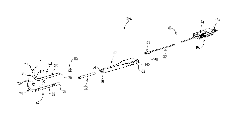
[4] The mucus membrane that lines the paranasal sinuses can become
inflamed. This
inflammation is known as sinusitis (or rhinosinusitis), and can be caused by
various factors such
as bacteria, viruses, allergies, anatomical abnormalities, etc. If the mucosa
of one of the
paranasal sinus passageways becomes inflamed, the passageway can become
blocked, trapping
mucus. Patients suffering from sinusitis can experience a number of symptoms
or
complications, such as headache, facial pain, toothache, inner ear problems,
etc.
[5] Sinusitis is typically classified as acute (infection lasting 4 or less
weeks) or chronic.
Many instances of acute sinusitis can be effectively treated with medication
(e.g.,
- 1 -
CA 2895205 2020-03-09
CA 02895205 2015-06-12
WO 2014/100174
PCT/US2013/076120
antibiotics, antihistamines, etc.). Chronic sinusitis may implicate a more
invasive
treatment option in which the paranasal passageways or affected sinuses are
surgically
accessed. Conventional sinus surgery entails an incision formed along the side
of the nose
or through the gums of the upper teeth to provide access to the targeted sinus
anatomy.
Once accessed, the paranasal sinus passageway in question is surgically
enlarged or
otherwise altered to facilitate resumption of mucus clearance.
161 More recently, corrective sinus surgery has been performed
endoscopically,
minimizing external trauma to the patient. With functional endoscopie sinus
surgery
(FESS) an endoscope is inserted into the nose. Using visualization through the
endoseope,
the anatomical and pathological obstructions associated with the sinusitis are
removed in
order to restore normal mucus clearance. The benefit of FESS (and other
intranasal
procedures) is the ability to allow for a more targeted approach to the
affected sinuses,
reducing tissue disruption and minimizing post-operative complications.
[71 An even more recent minimally invasive, intranasal sinus surgery is
known as
balloon sinus dilation or balloon sinuplasty. Balloon sinus dilation (or
simply "sinus
dilation") was initially developed to address the post-operative pain and
bleeding
associated with FESS. In general terms, conventional sinus dilation is an
endoseopic,
catheter-based procedure for treating sinusitis using a small, flexible
balloon catheter to
enlarge the affected sinus passageway(s). When the balloon is correctly
located and
inflated, it widens the walls of the sinus passageway, with the goal of
restoring normal
drainage without damaging the sinus lining.
(81 When performing sinus dilation, the surgeon inserts a sinus guide
catheter or
carmula through the nostril (or naris) to gain access to the affected sinus
ostia (opening)
under endoseopic visualization. A guide wire and/or illumination system are
then
introduced into the targeted sinus via the sinus guide catheter. Once access
to the intended
targeted location is confirmed by light or fluoroscopy, a flexible catheter,
carrying a
balloon, is introduced into the sinus cavity over the sinus guide wire,
locating the balloon
in the blocked ostium. In this regard, the illumination system provides
transeutaneous
- 2 -
CA 02895205 2015-06-12
WO 2014/100174
PCT/US2013/076120
(through the skin) light transmission that the surgeon relies upon when
estimating desired
balloon placement. Once the desired balloon position has been visually
confirmed, the
balloon is gradually inflated to dilate the narrowed or blocked ostium. The
balloon is then
deflated and removed. Next, an irrigation catheter may be advanced over the
guide wire to
flush out mucus. Finally, the sinus irrigation catheter is removed from the
sinus to allow
the sinus cavity to drain any mucus.
[91 While highly promising, existing sinus dilation systems and methods
have several
drawbacks. As highlighted by the above, available sinus dilation systems
require multiple
steps and multiple instruments. For example, some available sinus dilation
systems require
eighteen steps to complete a sinus dilation procedure. While the guide wire
can facilitate
accessing the targeted sinus site and use of a flexible balloon catheter,
surgeons must be
trained in the correct use of the guide wire, and the guide wire represents an
added cost.
Further, the required illumination source and use thereof is time-consuming
and relatively
expensive. Moreover, a surgeon is required to estimate a location of the
targeted ostium
only by illumination through the patient's skin. In some instances, the guide
wire and/or
illumination source may inadvertently be located in a "blind hole". As a point
of
reference, regions of the sinus system are pneumatized by various cells in
most patients.
These cells can build over time, collectively creating an anatomic variation,
hi some
instances, for example, Type II cells can occur at the frontal sinus and can
progress to a
level that is grossly akin to the frontal sinus ostium. It is estimated that
as many as 25% of
patients suffering from sinusitis of the frontal sinus have Type II cells.
When internally
illuminated (and viewed externally), a region of the Type II cell cluster may
appear (or
"feel") quite similar to the natural frontal sinus ostium opening, leading the
surgeon to
incorrectly assume that the desired ostium has been accessed. When the balloon
is
subsequently inflated, it may actually occlude the ostium rather than open the
ostium.
[10] In light of the above, the need exists for improved sinus dilation
systems and
methods.
- 3 -
CA 02895205 2015-06-12
WO 2014/100174
PCT/US2013/076120
Summary
[11] Some aspects in accordance with principles of the present disclosure
relate to a
surgical system for dilating a region of a patient's nasal sinus system. The
system includes
a surgical sinus dilation instrument having a handle, a rigid probe, and a
balloon. The rigid
probe is attached to the handle and extends distally therefrom. The probe
defines a
proximal end, a distal tip opposite the proximal end, and a curved segment
between the
proximal end and the distal tip. The balloon is secured to the probe adjacent
the distal end,
with an interior of the balloon being fluidly connected to an inflation path.
A curvature
and longitudinal location of the curved segment is configured to locate the
balloon within
one of a frontal, maxillary, or sphenoid sinus when inserted through a naris
or other
conventional sinus approach (e.g., canine fossa or open approach) of a
patient. A
connector is associated with the handle and is configured to be electronically
coupled to a
navigation or image guidance system (IGS). The tetras "navigation system",
"information
guidance system" and "IGS" are used interchangeably throughout this
disclosure. Finally,
an electronic identifier device is electronically coupled to the connector and
is programmed
to generate a signal indicative of an instrument identification assigned to
the sinus dilation
instrument. The instrument identification corresponds with the region of the
patient's
nasal sinus system the instrument is configured (e.g., specifically
configured) to access and
treat with the balloon. In this regard, the assigned instrument identification
is one of a
frontal sinus instrument, a maxillary sinus instrument, or a sphenoid sinus
instrument.
With this construction, a surgeon seeking to perform a sinus dilation
procedure simply
connects the sinus dilation instrument to an IGS via the connector. The IGS
automatically
recognizes the particular formatlinstrnment identification assigned to the
instrument, as
well as the dimensional features thereof In other words, once coupled, the IGS
directly or
indirectly "knows" the spatial location of the balloon or other relevant
portion/component
of the instrument (e.g., the IGS can be programmed to determine a spatial
location of a
distal tip of the shaft, where the balloon is secured in close proximity to
the distal tip, the
- 4 -
81789200
balloon location is thus also indirectly "known"). During the subsequent sinus
dilation
procedure, images generated by the IGS readily inform the surgeon of the
balloon location as
the instrument's probe is inserted into the nasal passageways and directed
toward the targeted
sinus region. The balloon is inflated to dilate the ostium, then deflated and
removed from the
patient. Systems and methods of the present disclosure entail minimal
components and are
easily used.
[12] In some embodiments, the system includes first-third sinus dilation
instruments each
having the curved, rigid probe and electronic identifier described above. The
rigid probe of a
first one of the instruments is configured for a frontal sinus procedure, the
second instrument's
probe for a maxillary sinus procedure, and the third instrument's probe for a
sphenoid sinus
procedure. When presented as a set or kit to a surgeon, the surgeon need only
select the
instrument shaped for the particular procedure in question, and then connect
the selected
instrument to the IGS.
112a1 According to one aspect of the present invention, there is provided a
surgical system for
dilating a region of a patient's nasal sinus system, the system comprising: a
first sinus dilation
instrument including: a handle defining a front end opposite a back end: a
rigid probe extending
distally from the front end of the handle, the rigid probe defining: a
proximal end at the front
end of the handle, a distal tip opposite the proximal end, a curved segment
between the proximal
end and the distal tip; a balloon having a distal end, the balloon being
secured over the rigid
probe adjacent the distal tip, wherein a distance between the distal end of
the balloon and the
distal tip is invariable; an inflation path fluidly connected to an interior
of the balloon; wherein
a curvature and a longitudinal location of the curved segment is configured to
locate the balloon
within one of a frontal sinus, a maxillary sinus, and a sphenoid sinus
following insertion of the
distal tip through a naris of the patient; a connector associated with the
handle and configured
to be electronically coupled to an image guidance system of the type to allow
for a display of a
position of the fist sinus dilation instrument within the patient relative to
a pre-operative image
of the patient's anatomy; and an electronic identifier device electronically
coupled to the
connector and programmed to generate a signal indicative of an instrument
identification
assigned to the first sinus dilation instrument and corresponding with one
region of the patient's
- 5 -
Date Recue/Date Received 2020-06-26
81789200
sinus system the first sinus dilation instrument is configured to access and
treat with the balloon,
the instrument identification selected from the group consisting of a frontal
sinus instrument, a
maxillary sinus instrument, and a sphenoid sinus instrument; and a second
sinus dilation
instrument including: a handle, a rigid probe extending from the handle and
forming a curved
segment, a balloon secured over the rigid probe adjacent a distal tip thereof
and fluidly
connected to an inflation path, a connector configured to be electronically
coupled to the image
guidance system, and an electronic identifier device electronically coupled to
the connector and
programmed to generate a signal indicative of an instrument identification
assigned to the
second sinus dilation instrument and selected from the group consisting of a
frontal sinus
instrument, a maxillary sinus instrument, and a sphenoid sinus instrument;
wherein the
instrument identification of the first sinus dilation instrument is different
from the instrument
identification of the second sinus dilation instrument; and further wherein
the electronic
identifier device of the first sinus dilation instrument is separate from the
electronic identifier
device of the second sinus dilation instrument.
112b1 According to another aspect of the present invention, there is provided
a surgical system
for dilating a region of a patient's nasal sinus system, the system
comprising: a first sinus
dilation instrument including: a first handle defining a front end opposite a
back end; a first
rigid probe extending distally from the front end of the first handle, the
first rigid probe defining:
a proximal end at the front end of the first handle, a first distal tip
opposite the proximal end, a
first curved segment between the proximal end and the first distal tip; a
first balloon secured
over the first rigid probe adjacent the first distal tip, wherein a spatial
location of the first balloon
relative to the first curved segment is fixed; a first inflation path fluidly
connected to an interior
of the first balloon; wherein a curvature and a longitudinal location of the
first curved segment
is configured to locate the first balloon within one of a frontal sinus, a
maxillary sinus, and a
sphenoid sinus following insertion of the first distal tip through a naris of
the patient; a first
connector associated with the first handle and configured to be electronically
coupled to an
image guidance system; and a first electronic identifier device electronically
coupled to the first
connector and programmed to generate a first signal indicative of a first
instrument
identification assigned to the first sinus dilation instrument and
corresponding with a region of
- 5a -
Date Recue/Date Received 2020-06-26
81789200
the patient's sinus system that the first sinus dilation instrument is
configured to access and treat
with the first balloon, the first instrument identification selected from the
group consisting of a
frontal sinus instrument, a maxillary sinus instrument, and a sphenoid sinus
instrument; and a
second sinus dilation instrument including: a second handle, a second rigid
probe extending
from the second handle and forming a second curved segment, a second balloon
secured over
the second rigid probe adjacent a second distal tip thereof and fluidly
connected to a second
inflation path, a second connector configured to be electronically coupled to
the image guidance
system, and a second electronic identifier device electronically coupled to
the second connector
and programmed to generate a second signal indicative of a second instrument
identification
assigned to the second sinus dilation instrument and selected from the group
consisting of a
frontal sinus instrument, a maxillary sinus instrument, and a sphenoid sinus
instrument; wherein
the first instrument identification of the first sinus dilation instrument is
different from the
second instrument identification of the second sinus dilation instrument; and
further wherein
the first electronic identifier device of the first sinus dilation instrument
is separate from the
second electronic identifier device of the second sinus dilation instrument.
1120 According to another aspect of the present invention, there is provided a
method of
dilating a region of a patient's nasal sinus system, the method comprising:
receiving a first sinus
dilation instrument configured for accessing the region of the patient's nasal
sinus system, the
first sinus dilation instrument including: a handle, a rigid probe extending
distally from the
handle, the rigid probe defining: a proximal end attached to the handle, a
distal tip opposite the
proximal end, a curved segment between the proximal end and the distal tip, a
balloon secured
to the rigid probe adjacent the distal tip, an inflation path fluidly
connected to an interior of the
balloon, a connector associated with the handle and configured to be
electronically coupled to
an image guidance system, and an electronic identifier device electronically
coupled to the
connector and programmed to generate a signal indicative of an instrument
identification
assigned to the first sinus dilation instrument and corresponding with a
region of a patient's
sinus system the first sinus dilation instrument is configured to access and
treat with the balloon,
the instrument identification selected from the group consisting of a frontal
sinus instrument, a
maxillary sinus instrument, and a sphenoid sinus instrument; electronically
coupling the
- 5b -
Date Recue/Date Received 2020-06-26
81789200
connector to an image guidance system, wherein the image guidance system is
programmed to
automatically recognize the instrument identification of the first sinus
dilation instrument;
inserting the distal tip through a naris of the patient with the balloon in a
deflated arrangement;
pushing the distal tip end along the nasal sinus system of the patient to a
target site; wherein the
step of pushing includes reviewing images generated by the image guidance
system and
indicative of a location of the balloon relative to the patient's nasal sinus
system; inflating the
balloon to dilate the target site; deflating the balloon after dilating the
target site; and removing
the first sinus dilation instrument from the patient.
112d1 According to another aspect of the present invention, there is provided
a method of
dilating a region of a patient's nasal sinus system, the method comprising:
providing a set of
sinus dilation instruments including a first sinus dilation instrument and a
second sinus dilation
instrument; wherein the second sinus dilation instrument includes an
electronic identifier device
programmed to generate a signal indicative of an instrument identification
assigned to the
second sinus dilation instrument; selecting a first sinus dilation instrument;
wherein the first
sinus dilation instrument includes: a handle, a rigid probe extending distally
from the handle,
the rigid probe defining: a proximal end attached to the handle, a distal tip
opposite the proximal
end, a curved segment between the proximal end and the distal tip, a balloon
secured to the rigid
probe adjacent the distal tip, an inflation path fluidly connected to an
interior of the balloon, a
connector associated with the handle and configured to be electronically
coupled to an image
guidance system, and an electronic identifier device electronically coupled to
the connector and
programmed to generate a signal indicative of an instrument identification
assigned to the first
sinus dilation instrument, the instrument identification of the first sinus
dilation instrument
differing from the instrument identification assigned to the second sinus
dilation instrument;
selecting the first sinus dilation instrument: electronically coupling the
connector of the first
sinus dilation instrument to an image guidance system, wherein the image
guidance system is
programmed to automatically recognize the instrument identification of the
first sinus dilation
instrument as well as spatial parameters of the first sinus dilation
instrument; inserting the distal
tip through a naris of the patient with the balloon of the first sinus
dilation instrument in a
deflated arrangement; pushing the distal tip end of the first sinus dilation
instrument along the
- 5c -
Date Recue/Date Received 2020-06-26
81789200
nasal sinus system of the patient to a target site, the target site selected
from the group consisting
of the instrument identification selected from the group consisting of a
frontal sinus, a maxillary
sinus, and a sphenoid sinus; wherein the step of pushing includes reviewing
images generated
by the image guidance system and indicative of a location of the balloon of
the first sinus
dilation instrument relative to the patient's nasal sinus system; inflating
the balloon of the first
sinus dilation instrument to dilate the target site; deflating the balloon of
the first sinus dilation
instrument after dilating the target site; and removing the first sinus
dilation instrument from
the patient.
Brief Description of the Drawings
[13] FIG. 1 is a schematic illustration of a surgical sinus dilation system in
accordance with
principles of the present disclosure and with portions shown in block form;
[14] FIG. 2 is an exploded perspective view of a frontal sinus dilation
instrument useful with
the system of FIG. 1;
[15] FIG. 3 is a side view of the frontal sinus dilation instrument of FIG. 2;
[16] FIG. 4 is a cross-sectional view of the frontal sinus dilation instrument
of FIG. 2;
[17] FIG. 5 A is a side view of a sheath useful with the instrument of FIG. 2;
[18] FIG. 5B is an enlarged cross-sectional view of a portion of the sheath
of FIG. 5A;
- 5d -
Date Recue/Date Received 2020-06-26
CA 02895205 2015-06-12
WO 2014/100174
PCT/US2013/076120
[19] FIG. 6A is an enlarged view of a portion of the instrument of FIG. 4;
[20] FIG. 6B is an enlarged view of another portion of the instrument of FIG.
4;
[21] FIG. 7 is an enlarged view of a portion of the instrument of FIG. 2,
illustrating a
balloon in a deflated state;
[22] FIG. 8 is an exploded, perspective view of a maxillary sinus dilation
instrument
useful with the system of FIG. 1;
[23] FIG. 9 is a cross-sectional view of the maxillary sinus dilation
instrument of FIG.
8;
[24] FIG. 10 is an exploded, perspective view of a sphenoid sinus dilation
instrunient
useful with the system of FIG. 1;
[25] FIG. 11 is a cross-sectional view of the sphenoid sinus dilation
instrument of FIG.
10;
[26] FIGS. 12A-12D illustrate use of the system of FIG. 1 in performing a
sinus dilation
procedure; and
[27] FIG. 13 is a simplified side view of another sinus dilation instrument in
accordance
with principles of the present disclosure.
Detailed Description
[28] One embodiment of a surgical sinus dilation system 20 in accordance with
principles of the present disclosure is shown in FIG. 1. The system 20
includes one or
more sinus dilation instruments 22, an image guidance system ("IGS") 24 and an
inflation
device 26. The components are described in greater detail below. In general
terms,
however, the instrument 22 is sized and shaped for locating a balloon 28
(identified for the
- 6 -
CA 02895205 2015-06-12
WO 2014/100174
PCT/US2013/076120
instrument 22A in FIG. 1) carried thereby at a particular targeted sinus
region (e.g., frontal
sinus, maxillary sinus, or sphenoid sinus) via a patient's naris (or
alternatively sized and
shaped for accessing the targeted sinus region through other conventional
approaches such
as canine fossa or open approach). Further, the instrument 22 is configured to
electronically interface with the IGS 24, with the IGS 24 programmed to
automatically
recognize size and shape attributes of the instrument 22. Finally, the
inflation device 26 is
selectively fluidly connected to the instrument 22, and operates to effectuate
inflation and
deflation of the balloon 28. With this construction, use of the system 20 in
treating the
paranasal sinus system of a patient entails electronically coupling the
instrument 22 to the
IGS 24. Once connected, the IGS 24 provides the surgeon with visual
representations
indicative of the balloon 28 relative to the patient's anatomy (e.g., a
"crosshair" icon
representing the distal tip of the instrument 22 superimposed on images of the
patient's
anatomy) as the surgeon maneuvers the instrument 22 to bring the balloon 28 to
the
paranasal sinus target site. The inflation device 26 is operated to inflate
the balloon 28,
thereby expanding the sinus ostium (or other region of the accessed sinus) as
desired.
Following deflation of the balloon 28, the instrument 22 is removed from the
patient and
the procedure is complete. In some embodiments, the system 20 includes two or
more of
the sinus dilation instruments 22, each sized and shaped for accessing a
different sinus
region of a patient (via an intranasal approach). Once the surgeon has
determined the
paranasal sinus to be treated, the surgeon selects the appropriately sized and
shaped sinus
dilation instrument, electronically (wired or wireless) connects the selected
instrument 22
with the IGS 24, and then performs the procedure as outlined above. The IGS 24
automatically "recognizes" the selected instrument 22 and generates imaging
information
based upon the now known spatial parameters of the instrument being used.
1291 One embodiment of a sinus dilation instrument 22A useful with the system
20 is
shown in FIGS. 2-4, and is configured or formatted (e.g., specifically
configured or
formatted) for performing a frontal sinus procedure. The instrument 22A
includes a handle
40, a rigid probe or shaft 42, a sheath 44 providing the balloon 28, an IGS
connector
assembly 46, an identifier device 48 (referenced generally), and a tracking
device 50. In
- 7 -
CA 02895205 2015-06-12
WO 2014/100174
PCT/US2013/076120
general terms, the rigid probe 42 is attached to the handle 40 and carries the
balloon 28.
The IGS connector assembly 46 extends from the handle 40 and is adapted for
electronic
coupling with the IGS 24 (FIG. 1). The identifier device 48 is configured to
electronically
store instrument identification information indicative of a particular sinus
location or sinus
procedure assigned to the instrument 22A (i.e., frontal sinus). Further, the
identifier device
48 is electronically connected to, or provided as part of, the IGS connector
assembly 46
such that when the IGS connector assembly 46 is coupled to the IGS 24, the
instrument
identification information generated by the identifier device 48 is
communicated to the IGS
24. The IGS 24, in turn, is programmed to recognize the instrument
identification
information provided by the identifier device 48 and reference known
geometries of the
instrument 22A. The IGS 24 can further facilitate use of the instrument 22A in
perfonning
a sinus dilation procedure by referencing information provided to or from the
tracking
device 50.
1301 The handle 40 can assume a variety of forms and in some embodiments is
formed
of a hardened, surgically safe material such as plastic or metal. While the
handle 40 can
have the generally cylindrical, streamlined shape shown, any other shape
conducive to
grasping and manipulating by a user's hand is equally acceptable.
1311 As described in greater detail below, the handle 40 can incorporate
various features
configured to interface with or retain other components of the instrument 22A.
In more
general terms, the handle 40 forms or defines a leading end 60, a trailing end
62, a
passageway 64, and a cavity 66 (FIG. 4).
1321 The rigid probe 42 is mounted to the handle 40, and is formed of a rigid,
surgically
safe material such as stainless steel (e.g., hard tempered stainless steel).
While the handle
40 and the rigid probe 42 have been illustrated and described as being
separately formed
and subsequently assembled to one another, in other embodiments the handle 40
and the
rigid probe 42 are integrally formed as a single, homogenous body. As best
shown in
FIGS. 2 and 4, the rigid probe 42 is an elongated body defining a proximal end
70, a distal
tip 72, and an intermediate, curved segment 74. In some embodiments and as
identified in
- 8 -
CA 02895205 2015-06-12
WO 2014/100174
PCT/US2013/076120
FIG. 4, the rigid probe 42 further fauns an inflation lumen 76 extending from
a proximal
end opening 78 to a side port 80 that is otherwise fluidly open to an exterior
surface 82 of
the probe 42.
1331 The curved segment 74, as well as a longitudinal length of the rigid
probe 42, is
configured for accessing the frontal sinus via the naris (such that the
instrument 22A can
also be referred to as a "frontal sinus dilation instrument"). In this regard,
the rigid probe
42 can be mounted to the handle 40 in a variety of manners (insert molded,
adhesive,
welded, press fit, etc.), with the rigid probe 42 extending distally from the
leading end 60
of the handle 40. For example, as shown in FIG. 4, the handle 40 is press fit
over the rigid
probe 42 such that the proximal end 70 is encompassed within the handle 40
(e.g., the
proximal end 70 is lodged within the passageway 64). With this construction, a
spatial
location of the curved segment 74 and the distal tip 72 relative to the
leading end 60 is
designed to be appropriate for accessing (via the naris or other conventional
approach) the
frontal sinus and locating the curved segment 74 at the ostium or narrow
drainage path of
the frontal sinus.
[34] The rigid probe 42 defines a proximal section 90 and a distal section 92
at opposite
sides of the curved segment 74, and in some embodiments the proximal section
90 extends
in a linear fashion from the leading end 60 to the curved segment 74.
Alternatively, one or
more bends can be formed along the proximal section 90. The distal section 92
can have a
linear shape in extension from the curved segment 74 to the distal tip 72. As
a point of
reference, the rigid probe 42 can include features between the proximal
section 90 and the
proximal end 70 that facilitate assembly to the handle 40. For example, a
region 94 can
have an enlarged diameter (as compared to a diameter of a remainder of the
rigid probe 42)
sized for press fit engagement with the handle 40.
[35] A shape of the curved segment 74 can be defined in terms of an angular
relationship the curved segment 74 establishes between the proximal section 90
and the
distal section 92. For example, the distal section 92 is orientated 70 -120
to the proximal
section 90, alternatively 85 - 105 . In related embodiments, the distal tip
72 is off-set
- 9 -
CA 02895205 2015-06-12
WO 2014/100174 PCT/US2013/076120
from a centerline of the proximal section 90 by a distance in the range of 22-
42 mm.
Regardless, the curved segment 74 has a radius of curvature and bend angle
appropriate for
locating the distal tip 72 at or adjacent a frontal sinus ostium (it being
understood that the
frontal sinus typically does not have a distinct ostium as otherwise found
with the
maxillary and sphenoid sinuses; instead, the frontal sinus "ostium" is akin to
a narrow
drainage path) of a typical adult patient when the distal tip 72 is inserted
through the naris
and manipulated through the corresponding paranasal sinus passageways. For
example,
the curved segment 74 may have two or more distinct bends, with the
predominant bend
having a continuous radius of curvature in the range of 14-34 mm, and a bend
angle in the
range of 78 418'. In related embodiments, it has surprisingly been found that
providing
_________ the curved segn lent 74 with two distinct bends (as shown best in
FIG. 6A), with the distal-
most bend locating the distal tip 72 at a bend angle of less than 90 , a
"reverse bend" is
effectuated by the curved segment 74 and serves as a safety feature in that as
the rigid
probe 42 is directed toward the frontal sinus ostium, the distal tip 72 is
directed away from
the patient's brain.
[36] In some embodiments, an outer diameter of the rigid probe 42 tapers along
at least
a portion of the curved segment 74 to the distal tip 72. With these
constructions, the outer
diameter at the proximal section 90 is greater than the outer diameter at the
distal tip 72. In
other embodiments, the rigid probe 42 can have a more unifon-n outer diameter.
Regardless, a rigidity of the rigid probe 42 (e.g., as dictated by a material,
construction
and/or outer diameter of the rigid probe 42) robustly maintains a spatial
position of the
distal tip 72 relative to the handle 40, and in particular relative to the
leading end 60. For
example, where the handle 40 is held stationary and a force of 1 lb is applied
to the distal
tip 72 in a direction opposite a curvature of the curved segment 74, the
curved segment 74
will deflect no more than 1 mm. Alternatively, the rigid probe 42 can exhibit
an enhanced
stiffness, or may be slightly less rigid, along the curved segment 74. As used
throughout
the specification, however, the term "rigid probe" specifically excludes a
conventional,
flexible catheter.
- 10 -
CA 02895205 2015-06-12
WO 2014/100174
PCT/US2013/076120
[37] To maintain the above-described rigidity or stiffness, the rigid probe 42
is a solid
structure along at least the curved segment 74. For example, the inflation
lumen 76 has a
relatively short length, and terminates in close proximity to the leading end
60 of the
handle 40 such that a majority (e.g., at least 75%) of the proximal section
90, as well as an
entirety of the curved segment 74 and the distal section 92, are solid in
cross-section. This
solid configuration provides the desired rigidity while allowing the distal
tip 72 and the
curved segment 74 to have a relatively small outer diameter (and thus highly
conducive to
intranasal insertion). Because the inflation lumen 76 terminates at a location
well-spaced
from the curved segment 74 and the balloon 28 is located along the curved
segment 74, an
inflation path to the balloon 28 is established, at least in part, at an
exterior of the rigid
probe 42 as described below. In other embodiments, however, the rigid probe 42
can be
more akin to a tube, with the inflation lumen 76 extending to the curved
segment 74 (and
the rigid probe 42 incorporating other design features that provide the
stiffiiess or rigidity
characteristics described above).
1381 In some embodiments, the handle 40 is constructed to provide access to
the
inflation lumen 76. For example, the handle 40 can form or include a connector
port 100
(e.g., a luer connector) at the trailing end 62 that is fluidly connected to
the inflation lumen
76 via the passageway 64. With these and other constructions, the proximal end
70 (and
thus the proximal end opening 78) is within the handle 40. Alternatively, the
rigid probe
42 can be mounted to the handle 40 such that the proximal end 70 is external
the handle 40
and can directly receive auxiliary tubing (not shown) from the inflation
device 26 (FIG. 1)
directly at the proximal end opening 78. A variety of other port
configurations are equally
acceptable that facilitate fluid coupling of the inflation lumen 76 to
auxiliary tubing from
the inflation device 26. In some embodiments, the sinus dilation instrument
22A includes
a volume element 102 disposed within the passageway 64. The volume element 102
is a
generally cylindrical body having an outer diameter slightly less than a
diameter of the
passageway 64. Thus, inflation medium introduced at the port 100 will flow
within the
passageway 64, about the volume element 102, to the inflation lumen proximal
end
opening 78. An overall size or volume of the volume element 102 is a function
of a
- 11 -
CA 02895205 2015-06-12
WO 2014/100174
PCT/US2013/076120
volume of the passageway 64 and a volume of the balloon 28. More particularly,
the
volume element 102 compliments the size of the balloon 28 so that the apparent
volume of
any of the sinus dilation instruments disclosed herein will be the same. For
example, an
instrument with a larger balloon volume will utilize a larger volume element
102 as
compared to an instrument (with the same sized passageway 64) with a smaller
balloon
volume. As a result, each of the instruments will have the same total volume
(i.e.,
available internal volume within the passageway 64 (as reduced by the volume
element
102) plus the volume of the balloon 28). In other embodiments, the volume
element 102
can be omitted or replaced by a fluid connector.
1391 The balloon 28 is secured over the rigid probe 42, and is comprised of a
semi-
compliant material (e.g., nylon, nylon derivatives, Pebax, polyurethane, PET,
etc.). In
some embodiments, and as best shown in FIG. 2, the balloon 28 is provided or
formed as
part of the sheath 44. The sheath 44 can be a homogeneous, extruded tubular
body that
defines the balloon 28, a base 110 and a tail 112. The base 110 extends
proximally from a
proximal end 114 of the balloon 28, and is generally sized and shaped in
accordance with a
size and shape of the rigid probe 42 (and in particular the proximal section
90) for reasons
made clear below. Similarly, the tail 112 extends distally from a distal end
116 of the
balloon 28, and is sized and shaped to receive the distal tip 72 of the rigid
probe 42.
[401 The balloon 28 can be defined along a length of the sheath 44 in various
manners,
and is generally characterized as being more readily expandable than the base
110 and the
tail 112. One construction of the sheath 44 is shown in greater detail in
FIGS. 5A and 5B.
As a point of reference, the sheath 44 is shown in the exploded view of FIG. 2
as
exhibiting a self-maintained curvature; as reflected in FIGS. 5A and 5B,
however, the
sheath 44 as a standalone component need not have a definitive curvature but
instead is
sufficiently flexible to generally follow or conform to a shape or curvature
of the rigid
probe 42 (FIG. 2) upon final assembly. The sheath 44 can be formed by first
and second
sections 120, 122. The sections 120, 122 are tubular, and can be separately
formed and
subsequently assembled in completing the sheath 44. The first section 120
defines a
-12-
CA 02895205 2015-06-12
WO 2014/100174
PCT/US2013/076120
majority of the base 110, and can taper in diameter at a leading end 124. The
second
section 122 forms the balloon 28, the tail 112, and a small portion of the
base 110. The
sections 120, 122 can be bonded to one another as shown. As best reflected in
FIG. 5B, a
wall thickness of the sheath 44 along the balloon 28 is less than the wall
thickness along
the base 110 and the tail 112. With this configuration, the proximal and
distal ends 114,
116 of the balloon 28 arc effectively defined by a transition in wall
thickness of the sheath
44 from the thinner balloon 28 to the thicker base 110 and tail 112. Due to
the increased
wall thickness, the base 110 and the tail 112 experience minimal, if any,
expansion when
the sheath 44 is subjected to expected operational inflation pressures (e.g.,
12 ATM or
less). Further, the balloon 28 expands to, but not beyond, a preformed size
and shape
reflected in FIG. 5B at the expected operational inflation pressures. In some
embodiments,
the balloon 28 is configured to have a maximum outer diameter upon inflation
of about 7
mm, alternatively about 6 mm, alternatively about 5 mm, and to maintain this
pre-
determined maximum outer diameter upon inflation at inflation pressures up to
at least 10
ATM.
[41] The balloon 28 optionally includes a marker 124 at or adjacent the
proximal end
114 (e.g., the marker 124 is a band etched into a material of the balloon 28
on a full
diameter of the balloon 28 at or adjacent the proximal end 114). The marker
124 thus
serves as a visual identifier as to a location of the balloon 28 relative to a
length of the rigid
probe 42 (FIG. 2) upon final assembly. For example, where the marker 124 is
located at
the proximal end 114 of the balloon 28, when the surgeon sees the marker 124
almost
entering the targeted ostium (e.g., via endoscopic visualization), s/he has
confirmation that
the balloon 28 is in the ostium.
[42] The tail 112 can assume various forms conducive to mounting with the
rigid probe
distal tip 72 (FIG. 2). For example, and as best shown in FIG. 5B, the tail
112 can be a
tube terminating at an open end 126. An inner diameter of the tail 112
approximates an
outer diameter of the rigid probe distal tip 72 such that the tail 112 can
nest over the distal
tip 72. Other constructions are also acceptable and the tail 112 can
alternatively be closed
- 13 -
CA 02895205 2015-06-12
WO 2014/100174
PCT/US2013/076120
at the end 126. With reference between FIGS. 2 and 4, the sheath 44 is sized
and shaped in
accordance with the rigid probe 42 such that sheath 44 can be fully assembled
over the
rigid probe 42. More particularly, the rigid probe 42 is loaded into the
sheath 44 until the
distal tip 72 is nested within the tail 112, and the base 110 surrounds the
proximal section
90. As shown in FIG. 6A for example, the tail 112 is received over the distal
tip 72, with
the open end 126 located along a length of the distal tip 72. The tail 112 is
attached to an
exterior of the distal tip 72 in a sealed manner, for example by bonding the
tail 112 to the
distal tip 72. Alternatively or in addition, a sealing body (e.g., a domed
cover) can be
inserted over the tail 112 to effectuate a more secure affixment of the tail
112 to the distal
tip 72. In other embodiments, a bond body can be molded over the distal tip 72
and
provides a material surface approximate for bonding with the tail 112. Various
other
techniques and corresponding mounting assemblies capable of securing the tail
112 with
the distal tip 72 in a sealed manner are also envisioned.
143] FIG. 6A further reflects that upon final assembly, the sheath 44
generally conforms
to a shape of the rigid probe 42, following a curvature of the curved segment
74 as well as
the tapering outer diameter of the distal tip 72. As a point of reference,
FIG. 6A illustrates
the balloon 28 in the inflated or expanded state. Due to the curvature of the
curved
segment 74, the sheath base 110 may be slightly displaced from an interior
side of the
curvature of curved segment 74 and/or portions of the inflated balloon 28 may
not be
centered relative to the rigid probe 42. However, a concentric relationship of
the balloon
28 relative to the rigid probe 42 does not affect use of the balloon 28 in
performing a sinus
dilation procedure as described below. Further, the balloon 28 consistently
expands or
inflates to the predetermined shape regardless of whether the balloon 28
remains centered
about the rigid probe 42.
144] Returning to FIGS. 2 and 4, a proximal side 130 of the sheath 44 is
secured to the
exterior surface 82 of the rigid probe 42 in a fluid tight manner by a ring
132 or other
device (e.g., adhesive). Regardless, a seal 134 is defined between the sheath
44 and the
exterior surface 82, with the seal 134 being located proximal the side port 80
as shown in
- 14 -
CA 02895205 2015-06-12
WO 2014/100174
PCT/US2013/076120
FIG. 6B. With this arrangement, an inflation path 136 is defined between the
exterior
surface 82 and the sheath 44, extending along the base 110 to the balloon 28
(FIG. 6A).
Further, the inflation path 136 continues to the balloon 28 as identified in
FIG. 6A. As a
point of reference, an inner diameter of the sheath base 110 is, in some
embodiments, only
slightly greater than the outer diameter of the rigid tube proximal section 90
as reflected in
FIGS. 2 and 6B.
[45] With the above constructions, the balloon proximal and distal ends 114,
116 are not
directly bonded to the exterior surface 82 of the rigid probe 42. Thus, an
inflation region
140 is defined for the balloon 28 that is fluidly open to the inflation path
136 (e.g., because
the proximal end 114 of the balloon 28 is not bonded to the rigid probe
exterior surface 82,
fluid flow through the inflation path 136 can enter the inflation region 140).
Other
constructions that fluidly connect the balloon inflation region 140 with an
inflation path are
also acceptable. For example, the rigid probe 42 can form a lumen extending to
the
inflation region 140. Alternatively, a lumen running parallel to the rigid
probe 42 (e.g., a
lumen formed or carried entirely by the sheath 44) can be provided.
Regardless, in some
constructions, the balloon 28 forms one or more pleats 142 in the deflated (or
contracted)
state shown in FIG. 7. The pleats 142 promote folding of the balloon 28 onto
the rigid
probe 42 as the balloon 28 is deflated, thereby minimizing an outer profile of
the
instrument 22A along the balloon 28. Alternatively, other assembly techniques
can be
employed that may or may not include folds or pleats being formed in the
balloon 28.
Regardless, in some constructions, assembly of the balloon 28 to the rigid
probe 42
provides an outer diameter on the order of 2-3 MIT1 in the deflated or
contracted stale.
[46] The IGS connector assembly 46 is configured to interface with the IGS 24
(FIG. 1)
as described below, and thus can have a format selected in accordance with the
particular
IGS 24. In some embodiments, the IGS connector assembly 46 includes a
connector 160
and a cable 162. The connector 160 carries appropriate circuitry 164 for wired
coupling to
the IGS 24. In other embodiments, the connector 160 can be configured for
wireless
interface with the 1GS 24. The cable 162 fornis a terminal 166 opposite the
connector 160
- 15 -
CA 02895205 2015-06-12
WO 2014/100174
PCT/US2013/076120
that is assembled to the handle 40. For example, the terminal 166 can be
potted within the
cavity 66.
[47] In some embodiments, the identifier device 48 is associated with the
connector 160
and is electronically connected to the connector circuitry 164. For example,
the identifier
device 48 can be a memory chip or similar circuitry component housed within
the
connector 160. Alternatively, the identifier device 48 can be assembled within
the handle
40. Regardless, the identifier device 48 is programmed or formatted to store
or generate
instrument identification information unique to the instrument 22A, and in
particular
identifying the instrument 22A as being a "frontal sinus dilation instrument"
or specifically
configured for a frontal sinus procedure. That is to say, the instrument
identification
assigned to the instrument 22A correlates to the region of a patient's nasal
sinus system for
which the instrument is configured to access and treat (i.e., the frontal
sinus) with the
balloon 28 via an intranasal approach (or other commonly used approach). The
instrument
identification information is electronically stored by the identifier device
48 in a format
compatible with the 1GS 24 (FIG. 1). As described below, the IGS 24 is
programmed with
reference data from which specific dimensional features of the so-identified
instrument
22A are obtained. This information, in turn, can be utilized by the IGS 24 in
various
operations, such as "tracking" the instrument 22A via the tracking device 50.
[48] In some embodiments, the tracking device 50 is an electromagnetically
detectable
receiver wire coil or plurality of wire coils that can either transmit an
electromagnetic field
or sense an electromagnetic field and generate a corresponding tracking signal
utilized by
the IGS 24 (FIG. 1). For example, the electromagnetic coil(s) of the tracking
device 50
can be potted in the handle cavity 66, or otherwise fonned as a wire wrapped
around a core
(e.g., formed of a solid material or air) or other axis and that can sense a
magnetic field by
generating a current within the wire, or transmit an electromagnetic field
that can be sensed
by a separate sensing at localizer coil provided with the IGS 24. Other
electromagnetic
sensors can be employed in addition to or as an alternative to the wire
coil(s), such as
magnetic resistive sensors, Hall-effect sensors, etc. The tracking device 50
can
- 16 -
CA 02895205 2015-06-12
WO 2014/100174
PCT/US2013/076120
alternatively assume other formats in accordance with the navigation
technology employed
by the IGS 24 (e.2., an infrared tracking device, an optical tracking device,
an acoustic
tracking device, a radiation tracking device, a radar tracking device, etc.).
With these and
other constructions, a location of the tracking device 50 within the handle 40
is fixed.
Because a spatial location of the distal tip 72 relative to the handle 40 is
also fixed (due to
the rigid construction of the rigid probe 42 as described above), a spatial
location of the
distal tip 72, and thus of the balloon 28 secured thereto, relative to the
tracking device 50 is
also fixed. As a result, tracking information provided by the tracking device
50 effectively
tracks movement and positioning of the distal tip 72 (and thus the balloon
28). The
tracking device 50 functions, alone or in combination with at least one
additional
electromagnetic coil (or other tracking-related component), to provide the
position of at
least a portion of the instrument 22A in three-dimensional space and in real-
time during a
sinus dilation or other paranasal sinus system procedure being performed on a
patient. In
some embodiments, the identifier device 48 is an electronic information
storage device
(e.g., a read only memory chip) provided apart from the tracking device 50. In
other
embodiments, the tracking device 50 is formatted to serve as both the
identifier device and
the tracking device. Additional navigation-related circuitry components can
optionally be
provided in alternative configurations, such as an accelerometer or other
inertial sensor,
such as a gyroscopic sensor.
[491 The tracking device 50 is electronically coupled to the cable terminal
166, with the
cable 162 carrying signaled information from the tracking device 50 to the
connector 160.
The connector 160, in turn, is thus compatible with one or more I/O
receptacles included
with the particular 1GS 24, and can facilitate other operational interfaces
between the
instrument 22A and the IGS 24 (e.g., where necessary, power can be delivered
to the
instrument 22A via the IGS connector assembly 46).
[50] Operation of the frontal sinus dilation instrument 22A is described in
greater detail
below. It will be understood, however, that the frontal sinus dilation
instrument 22A is
uniquely configured for frontal sinus dilation procedures. Principles of the
present
- 17-
CA 02895205 2015-06-12
WO 2014/100174
PCT/US2013/076120
disclosure are similarly provided in sinus dilation instruments uniquely
configured to
access sinuses other than the frontal sinus, several examples of which are
provided below.
[51] For example, another embodiment of a sinus dilation instrument 22B in
accordance
with principles of the present disclosure and useful with the system 20 (FIG.
1) is shown in
FIGS. 8 and 9. In certain respects, the instrument 22B is highly similar to
the frontal sinus
dilation instrument 22A (FIGS. 2-4) described above, but is configured for a
maxillary
sinus procedure. With this in mind, the instrument (or "maxillary sinus
dilation
instrument") 22B includes a handle 240, a rigid probe or shaft 242, a sheath
244 providing
a balloon 228, an IGS connector assembly 246, an identifier device 248
(referenced
generally), and a tracking device 250. The rigid probe 242 projects from a
leading end 260
of the handle 240, whereas the connector assembly 246 extends from a trailing
end 262.
The identifier device 248 is carried by the IGS connector assembly 246, and is
adapted to
electronically store instrument identification information indicative of the
maxillary sinus
designation assigned to or embodied by the instrument 22B. As a point of
reference, the
handle 240 and the IGS connector assembly 246 can be identical to the handle
40 and IGS
connector assembly 46 (FIGS. 2-4) described above.
1521 The rigid probe 242 is akin to the rigid 'Robe 42 (FIGS. 2-4) described
above (e.g.,
can be a solid metal body), and defines a proximal end 270, a distal tip 272,
and an
intermediate, curved segment 274. An inflation lumen 276 extends from a
proximal end
opening 278 to a side port 280 that is otherwise fluidly open to an exterior
surface 282 of
the rigid probe 242. As with previous embodiments, a portion of the rigid
probe 242 can
be mounted within the handle 240, with a proximal section 290 of the rigid
probe 242
being defined between the leading end 260 of the handle 240 and the curved
segment 274,
and a distal section 292 between the curved segment 274 and the distal tip
272. In some
embodiments, extension of the rigid probe 242 along the proximal section 290
and along
the distal section 292 is linear. A volume element 302 can optionally be
provided that
effectuates a desired apparent volume in a pathway 264 to the inflation lumen
276 from an
exterior of the handle 240.
- 18 -
CA 02895205 2015-06-12
WO 2014/100174
PCT/US2013/076120
[53] The curved segment 274 has a radius of curvature and bend angle
appropriate for
locating the distal tip 272 at or within the maxillary sinus ostium of a
typical adult patient
when the distal tip 272 is inserted through the patient's naris (or other
typical approach)
and manipulated through the corresponding paranasal sinus passageways. For
example,
the curved segment 274 can have a continuous radius of curvature in the range
of 1.6-9.6
mm and a bend angle in the range of 35 -75 . In other embodiments, a shape of
the curved
segment 274 is such that the distal section 292 is orientated 900-1400 to the
proximal
section 290, alternatively 110 -135 . In related embodiments, the distal tip
272 is radially
off-set from a centerline of the proximal section 290 by a distance in the
range of 6.4-16.4
mm. As a point of reference, the radius of curvature and bend angle of the
maxillary sinus
instrument's curved segment 274 is less than the radius of curvature and bend
angle
associated with the frontal sinus instrument's curved segment 74 (FIG. 4). As
with
previous embodiments, the rigid tube 242 exhibits sufficient stiffness or
rigidity to resist
overt deflection of the distal tip 272 in the presence of expected forces of a
sinus dilation
procedure.
1541 The sheath 244 can be highly akin to the sheath 44 (FIGS. 5A and 5B)
described
above in terms of structure, material, and performance. The sheath 244 is
formed, in some
embodiments, to homogeneously generate the balloon 228 between a base 310 and
a tail
312, with the sheath 244 having a reduced wall thickness along the balloon
228. The
sheath 244 increases in wall thickness at proximal and distal ends 314, 316 of
the balloon
228. The base 310 is sized and shaped to closely nest (e.g., fits over the
rigid probe 242
with a small clearance) over the proximal section 290 of the rigid probe 242,
and the tail
312 is configured to receive (and be sealed to) the distal tip 272. Upon final
assembly, a
ring 332 or other body (or adhesives) establishes a proximal seal 334 between
the sheath
244 and the exterior surface 282 of the rigid probe 242. The proximal seal 334
is proximal
the side port 280 to establish an inflation path 336 (referenced generally in
FIG. 9) between
the exterior surface 280 and the sheath 244 that fluidly connects the
inflation lumen 276
with an interior of the balloon 228. As illustrated, at least a portion of the
balloon 228
- 19 -
CA 02895205 2015-06-12
WO 2014/100174
PCT/US2013/076120
extends along the curved segment 274. As with previous embodiments, the
balloon 228 is
configured to expand to and maintain a preformed shape under expected
inflation
pressures.
[55] The identifier device 248 can be substantially identical to the
identifier device 48
(FIG. 2) described above, and can be a memory chip carried within a connector
360 of the
IGS connector assembly 246 and electronically connected to connector circuitry
364. As
with previous embodiments, the identifier device 248 is configured or
programmed to store
or generate instrument identification information indicative of the maxillary
sinus
designation assigned to the instrument 22B, with the IGS 24 (FIG. 1) in turn
being
programmed to "recognize" the maxillary sinus-related shape and dimensions
associated
with the instrument 22B upon connection (wired or wireless) to the connector
360 as
described above. Where both of the instruments 22A, 22B are provided with the
system 20
(FIG. 1), the instrument identification information embodied by the
corresponding
identifier devices 48, 248 each generate unique or distinct instrument
identification
information that is recognized by the IGS 24.
[56] As best shown in FIG. 9, in some embodiments, the instrument 22B further
includes the tracking device 250 (e.g., one or more electromagnetic coils)
configured to
generate tracking information that is acted upon by the IGS 24 (FIG. 1) during
use of the
instrument 22B in perfouning a maxillary sinus procedure. The instrument 22B
can
incorporate the tracking device 250 apart from the identifier device 248
(e.g., the identifier
device 248 can be a memory chip, with a separate electromagnetic wire coil(s)
serving as
the tracking device 250 mounted within the handle 240). In other embodiments,
the
electromagnetic wire coil(s) (or other tracking component) is formatted to
serve as both the
identifier device 248 and the tracking device 250.
[571 Another embodiment sinus dilation instrument 22C in accordance with
principles
of the present disclosure and useful with the system 20 (FIG. 1) is shown in
FIGS. 10 and
11. The instrument 22C can be, in many respects, highly similar to the
instruments 22A
- 20 -
CA 02895205 2015-06-12
WO 2014/100174
PCT/US2013/076120
(FIGS. 2-4) and 22B (FIGS. 8 and 9) described above, but is configured to
facilitate
accessing the sphenoid sinus via a patient's naris (or other conventional
approach).
[58] The instrument (or "sphenoid sinus dilation instrument") 22C includes a
handle
440, a rigid probe 442, a sheath 444 providing a balloon 428, an IGS connector
assembly
446, an identifier device 448 (referenced generally), and a tracking device
450. The handle
440 and the IGS connector assembly 446 can be identical to the handle 40 (FIG.
2) and the
IGS connector assembly 46 (FIG. 2), respectively, described above.
[59] The rigid probe 442 is akin to the rigid probes of previous embodiments
(e.g., the
rigid probe 442 can be a solid metal body), and defines a proximal end 470, a
distal tip
472, a first curved segment 474a and optionally a second curved segment 474b.
An
inflation lumen 476 extends from a proximal end opening 478 to a side port 480
that is
otherwise fluidly open to an exterior surface 482 of the rigid probe 442. The
proximal end
470 can, in some embodiments, be mounted within the handle 440, with the rigid
probe
442 projecting distally from a leading end 460 of the handle 440. A volume
element 502
can optionally be provided that effectuates a desired apparent volume in a
pathway 464 to
the inflation lumen 476 from an exterior of the handle 440. The first curved
segment 474a
is located between a proximal section 490 and a distal section 492, and is
configured to
locate the distal tip 472 at or within the sphenoid sinus ostium when the
distal tip 472 is
inserted through an adult patient's naris (or other conventional approach) and
manipulated
through the corresponding paranasal sinus passageways. With the sphenoid sinus
dilation
instrument 22C, the first curved segment 474a is longitudinally spaced from
the distal tip
472 (as compared to the frontal sinus dilation instrument 22A and the
maxillary sinus
dilation instrument 22B), and in some constructions the proximal and distal
sections 490,
492 are linear. Where provided, the second curved segment 474b is formed
adjacent the
distal tip 472.
[60] The first curved segment 474a can have a continuous radius of curvature
in the
range of 12.8-22.8 mm and a bend angle in the range of 100-500. In other
embodiments, a
shape of the first curved segment 474a is such that the distal section 492 is
orientated 1250-
- 21 -
CA 02895205 2015-06-12
WO 2014/100174
PCT/US2013/076120
175 to the proximal section 490, alternatively 140 -160 . Where provided, the
second
curved segment 474b can have a bend angle in the range of 8'48 , for example
13 .
Regardless, the distal tip 472 is radially off-set from a centerline of the
proximal section
490 by a distance in the range of 26.6-66.6 mm.
1611 The sheath 444 can be highly akin to the sheath 44 (FIGS. 2-4) described
above in
terms of structure, material, and performance. The sheath 444 homogeneously
forms the
balloon 428 between a base 510 and a tail 512, with the sheath 444 having a
reduced wall
thickness along the balloon 428. The sheath 444 increases in wall thickness at
proximal
and distal ends 514, 516 of the balloon 428. The base 510 is sized and shaped
to closely
nest (e.g., stretch) over the proximal section 490 of the rigid probe 442, and
the tail 512 is
configured to receive (and be sealed to) the distal tip 472. Upon final
assembly, a ring 532
or other body establishes a proximal seal 534 between the sheath 444 and the
exterior
surface 482 of the rigid probe 442. The proximal seal 534 is proximal the side
port 480 to
establish an inflation path 536 (referenced generally in FIG. 12) between the
exterior
surface 480 and the sheath 444 that fluidly connects the inflation lumen 476
with an
interior of the balloon 428. The balloon 428 can be longitudinally displaced
from the first
curved segment 474a and can be along the second curved segment 474b as shown.
1621 The identifier device 448 can be highly akin to the identifier devices
described
above, and in some embodiments is a memory chip carried within a connector 560
of the
IGS connector assembly 446. Once again, the identifier device 448 is
configured or
programmed to store or generate instrument identification information
indicative of the
sphenoid sinus designation assigned to the instrument 22C. The IGS 24 (FIG. 1)
is
programmed to automatically "recognize" the sphenoid instrument designation
assigned to
the instrument 22C upon connection (wired or wireless) with the connector 560,
and
distinguishes the sphenoid sinus dilation instrument 22C from the frontal
sinus dilation
instrument 22A (FIG. 2) and the maxillary sinus dilation instrument 22B (FIG.
9) with
embodiments in which the system 20 (FIG. 1) includes each of the instruments
22A-22C.
-22 -
CA 02895205 2015-06-12
WO 2014/100174
PCT/US2013/076120
[63] In some embodiments, the instrument 22C further includes the tracking
device 450
(e.g., one or morc electromagnetic coils) configured to generate tracking
information
utilized by the IGS 24 (FIG. 1) during a paranasal sinus treatment procedure
as described
above. In some embodiments, the instrument 22C incorporates the tracking
device 450
apart from the identifier device 448. Alternatively, the electromagnetic
tracking coil(s) (or
other tracking component) can be formatted to serve as both the identifier
device 448 and
the tracking device 450.
[64] As mentioned above and returning to FIG. 1, some embodiments of the
systems 20
of the present disclosure include a set or kit of surgical sinus dilation
instruments, such as
at least one frontal sinus dilation instrument 22A, at least one maxillary
sinus dilation
instillment 22R and at least one sphenoid sinus dilation instrument 22C. When
preparing
for a particular procedure, the surgeon selects the desired sinus dilation
instrument from
the set. Once connected, the IGS 24 is programmed to recognize the selected
instrument
22A-22C and utilize tracking information generated by the selected instrument
during a
sinus procedure. For example, the instruments 22A-22C can be calibrated prior
to delivery
to the user and the corresponding spatial parameters stored in a memory of the
IGS 24.
The IGS 24 recognizes the selected instrument from the received instrument
identification
information and can, in some embodiments, be programmed to display a name of
the
selected instrument to the user. In related embodiments, the IGS 24 is
programmed to
further display a size of the balloon (e.g., predetermined maximum inflation
diameter) to
the user.
[65] The IGS 24 can be of a type known in the art capable of tracking and
providing
anatomical imaging of the connected sinus dilation instrument 22 during a
paranasal sinus
treatment procedure. For example, the IGS 24 can be an electromagnetic-based
navigation
system such as the StealthStation 0 AxiEM TM surgical navigation system
available from
Medtronic Navigation, Inc. of Louisville, Colorado; a Fusion TM ENT Navigation
System
(electromagnetic image-guided surgery system) available from Medtronic-Xomed,
Inc. of
Jacksonville, Florida; etc. Exemplary image guidance systems are also
disclosed in U.S.
- 23 -
CA 02895205 2015-06-12
WO 2014/100174
PCT/US2013/076120
Patent Numbers 7,751,865; 5,913,820; and 5,592,939, the teachings of each of
which are
incorporated herein by reference. Other navigation technology is also
acceptable, such as
infrared, optical, acoustic, radiation, radar, etc. (with the sinus dilation
surgical
instrument's tracking device being formatted in accordance with the tracking
system). In
more general terms, the IGS 24 includes an instrument recognition module, a
tracking
module, and a display module. The instrument recognition module is programmed
to
interpret instrument identification information received from a selected sinus
dilation
instrument once electronically coupled to the IGS 24. The tracking module
operates to
track the sinus dilation instrument relative to a patient or within a
navigation space.
Finally, the display module can use image data from an imaging device (e.g.,
an 0-arm
imaging device available from Medtronic Navigation, Inc. of Louisville,
Colorado) to
display on a display screen locations of the tracked instrument relative to
the patient's
anatomy. Thus, the IGS 24 serves to assist a surgeon in navigating the sinus
dilation
instrument 22 through the paranasal sinus passageways.
[661 Various optional features of the IGS 24 are described in U.S. Publication
No.
2012/0197110, the teachings of which are incorporated herein by reference.
With
electromagnetic tracking techniques, the tracking device associated with the
sinus dilation
instrument is one or more coils that can either transmit an electromagnetic
field or sense an
electromagnetic field to generate a tracking signal that in turn allows the
tracking module
of the IGS 24 to determine the location of the tracked instrument in the
navigation space.
Electromagnetic navigation in accordance with some aspects of the present
disclosure
utilizes a system that transmits three separate electromagnetic fields that
are received or
otherwise sensed by one or more electromagnetically detectable receiver coils
integrated
into the sinus dilation instrument to be tracked. At least one coil is used to
monitor the
three-dimensional location of that coil in three-dimensional space, as well as
the sinus
dilation instrument the coil is integrated with. Accurate registration of
previously acquired
anatomical images can be perfoimed using one or more surface fiducial
registration points,
internal, implanted, and indwelling reference devices, for example. The form
of reference
- 24 -
CA 02895205 2015-06-12
WO 2014/100174
PCT/US2013/076120
points required to register the image to the true anatomy, if any, depends on
the accuracy
needed for the particular procedure and anatomy of interest.
1671 The display module associated with the IGS 24 can assume a variety of
forms and
generally provides information regarding movement of the selected sinus
dilation
instrument relative to the patient. For example, any 2D, 3D or 4D imaging
device, such as
isocentric fluoroscopy, bi-plane fluoroscopy, ultrasound, computed tomography
(CT),
multi-slice computed tomography (MSCT), Ti weighted magnetic resonance imaging
(MRI), T2 weighted MRI, high frequency ultrasound (IIIFU), positron emission
tomography (PET), optical coherence tomography (OCT), may also be used to
acquire 2D,
3D or 4D pre-or post-operative and/or real-time images or image data of the
patient.
1681 Because the paranasal sinus dilation instruments (e.g., the instruments
22A-22C) of
the present disclosure incorporate a rigid probe carrying a balloon, the
tracking device
(e.g., wire coil) associated with each of the instruments can be mounted
within the
corresponding handle yet still provide viable tracking information relative to
the
instrument's distal tip (and thus the balloon carried thereby). Stated
otherwise, a spatial
location of the probe's distal tip (and thus the balloon) relative to the
handle (and thus
relative to the tracking device carried by the handle) will not change over
the course of a
particular paranasal sinus access procedure, unlike conventional balloon
catheter-based
sinus dilation teclmiques. As such, the tracking coil can assume a known, and
thus
relatively inexpensive, construction, and is easily and readily assembled to
the handle. The
sinus dilation instruments of the present disclosure are therefore cost
effective and provide
consistent, viable image navigation information.
[69] Sinus dilation methods in accordance with some embodiments of the present
disclosure can entail the surgeon receiving a set or kit of sinus dilation
instruments
comprising the frontal sinus dilation instrument 22A, the maxillary sinus
dilation
instrument 22B, and the sphenoid sinus dilation instrument 22C. The surgeon
evaluates
the paranasal sinus to be treated, and then selects the corresponding sinus
dilation
instrument from the set. For example, where the patient requires dilation of
the ostium of
- 25 -
CA 02895205 2015-06-12
WO 2014/100174
PCT/US2013/076120
one (or both) of the patient's maxillary sinuses, the maxillary sinus dilation
instrument 22B
is retrieved from the set. Alternatively, a "set" of three different
instruments 22A-22C
need not be provided to the surgeon as a kit. The patient is prepared and
arranged relative
to the IGS 24 in accordance with the protocols associated with the IGS 24
being used by
the surgeon. The IGS connector associated with the selected sinus dilation
instrument
22A, 22B, 22C is electronically coupled (wired or wireless) to a console of
the IGS 24.
Upon making this connection, the instrument recognition module of the IGS 24
automatically "recognizes" the selected instrument via the received instrument
identification information and accesses stored information relating to a
spatial location of
the balloon carried by the sinus dilation instrument relative to the
corresponding tracking
device. Stated otherwise, once the selected sinus dilation instrument is
electronically
coupled to the IGS 24, the IGS 24 automatically "knows", and thus can track, a
spatial
position of the probe's distal tip, and thus of the balloon, based upon
tracking information
generated by the tracking device otherwise provided with the instrument. Thus,
systems
and methods of the present disclosure effectively entail a "plug and play"
technique
whereby the surgeon simply selects and connects the desired sinus dilation
instrument to
the IGS 24 and can then begin the procedure.
[70] The selected sinus dilation instrument 22A, 22B, 22C is initially
operated in a
deflated state in which the balloon (e.g., the balloon 28 of FIGS. 2-4) is
contracted about
the corresponding rigid probe (e.g., the rigid probe 42 of FIGS. 2-4). The
paranasal sinus
to be treated is then accessed by the selected sinus dilation instrument. For
example,
FIGS. 12A-12D illustrate various steps of a method of accessing and dilating a
frontal
sinus FS using the frontal sinus dilation instrument 22A. With the surgeon
grasping the
instrument 22A at the handle 40 (FIG. 1), the distal tip 72 is initially
introduced into the
naris or nostril 600 (or other conventional approach) as shown in FIG. 12A.
The rigid
probe 42 is then further advanced through the patient's paranasal passageways,
bringing
the distal tip 72 adjacent an ostium (or narrow drainage path) 602 of the
frontal sinus FS.
With further advancement, and as shown in FIG. 12B, the balloon 28 is located
within the
ostium 602. Notably, the radius of curvature and bend angle of the curved
segment 74 is
- 26 -
CA 02895205 2015-06-12
WO 2014/100174
PCT/US2013/076120
configured to readily locate the balloon 28 at the frontal sinus ostium 602
via advancement
through the naris 600. Throughout the transitioning of the distal tip 72 from
initial
insertion within the naris 600 to the final position of FIG. 12B, the IGS 24
(FIG. 1)
continuously tracks movement of the frontal sinus dilation instrument 22A, and
presents
visual images (and/or other navigation information) indicative of the balloon
28 location
relative to the patient's anatomy (e.g., a erosshair-type icon representing
the distal tip 72
relative to images of the paranasal sinus passageway being traversed). Thus,
with systems
and methods of the present disclosure, no additional tools (e.g., guide wire)
or illumination
is necessary or required by the surgeon in achieving visually confirmed
balloon placement
at the targeted frontal sinus ostium 602. In other embodiments, an endoscope
(not shown)
or similar device can be employed along with the sinus dilation instrument
22A.
Conventionally, the endoscope carries a camera or other visualization device
that provides
the surgeon with a visual display of the actual anatomy within the endoscope's
field of
view. With embodiments in which the balloon 28 includes the marker 124 (best
shown in
FIG. 5B), as the balloon 28 is being advanced into the ostium 602, once the
marker 124
can no longer be seen in the endoscope's camera display, the surgeon can
determine that
the balloon 28 is now fully "inside" of the targeted ostium 602.
[711 Once the balloon 28 has been desirably located relative to the ostium
602, the
inflation device 26 (FIG. 1) is actuated to inflate the balloon 28 as shown in
FIG. 12C.
With this inflation or expansion, the ostium 602 is dilated as desired.
Subsequently, the
balloon 28 is deflated or otherwise contracted about the rigid probe 42,
followed by
withdrawal of the frontal sinus dilation instrument 22A from the patient. Upon
completion
of the procedure, the frontal sinus ostium 602 is dilated as shown in FIG.
12D.
[721 Under circumstances where treatment of the patient requires dilation of
other or
additional sinus ostiums, the surgeon simply selects the corresponding sinus
dilation
instrument, connects the selected instrument to the IGS 24 (FIG. 1), and
initiates accessing
and dilation of the desired ostium as described above.
-27 -
CA 02895205 2015-06-12
WO 2014/100174
PCT/US2013/076120
[73] In some embodiments, the sinus dilation instruments 22 of the present
disclosure
are relatively inexpensive, disposable surgical tools (e.g., one-time use).
Alternatively, in
other constructions, the sinus dilation instruments can incorporate various
structural
features (e.g., materials, seals, etc.) that facilitate surgically-safe
cleaning and sterilization
(e.g., autoclave sterilization) and are re-usable. In yet other embodiments,
the rigid probe
42 (FIG. 2) and the handle 40 (FIG. 2) are releasably mounted to one another.
With these
constructions, following a sinus dilation procedure, the rigid probe 42 (and
the balloon 28
carried thereby) is removed from the handle 40, the handle 40 is sterilized,
and a new rigid
probe/balloon assembly mounted to the handle 40. With these alternative
constructions,
then, the handle 40 (and the electronic components carried by the handle 40)
is re-usable.
In related embodiments, the electronic components (e.g., the identifier and
the tracking
device) are disposable and clipped on to the handle 40 prior to use. Following
completion
of the procedure, the electronic components are removed, and the handle
sterilized for re-
use.
[74] FIG. 13 illustrates another embodiment surgical sinus dilation instrument
700 in
accordance with principles of the present disclosure and akin to the frontal
sinus dilation
instrument 22A (FIGS. 2-4) described above. The instrument 700 includes a
handle 702, a
rigid probe 704, and a sheath 706 forming a balloon 708 (shown in an expanded
or inflated
state). The handle 702 and the rigid probe 704 can be identical to the handle
40 (FIGS. 2-
4) and the rigid probe 42 (FIGS. 2-4) described above. The sheath 706 can also
be highly
akin to the sheath 44 (FIGS. 5A and 5B), and forms a base 710 and a tail 712
at opposite
sides of the balloon 708. With the instrument 700 of FIG. 13, however, the
sheath 706 is
removably attached to the handle 702/probe 704.
[75] In particular, the base 710 terminates at a proximal collar 714. The
collar 714 is
sized and shaped to be sealing received within a gap 716 (referenced
generally) formed
between the handle 702 and the rigid probe 704. The sheath 706 is assembled
over the
rigid probe 704, with the collar 714 being press fit within the gap 716. The
tail 712 can be
footled to terminate at a closed end 716 that effectively seals against the
rigid probe 704.
- 28 -
CA 02895205 2015-06-12
WO 2014/100174
PCT/US2013/076120
Following use of the instrument 700, the sheath 706 can be removed, the handle
702/rigid
probe 704 sterilized, and a new sheath 706 assembled over the rigid probe 704
as described
above. In related embodiments, electrical components (e.g., device identifier,
tracking
device, and TGS connector assembly) are disposable and removably clipped to
the handle
702.
1761 Returning to FIG. 1, the inflation device 26 useful with the sinus
dilation systems
of the present disclosure can assume a variety of forms, and in some
embodiments is a
conventional syringe-type device. Saline or other surgically safe liquid can
be used as the
inflation medium.
1771 Sinus dilation systems and methods of the present disclosure provide a
marked
improvement over previous designs. The sinus dilation instruments are
specifically sized
and shaped to locate the corresponding dilation balloon directly at the sinus
ostium of
interest without the use of additional tools or steps. Further, the sinus
dilation instruments
are utilized with image guidance systems not otherwise relying upon an
internally
deployed illumination source, and can be quickly connected to the image
guidance system
on a "plug and play" basis. In this regard, the image guidance system
immediately
"recognizes" a selected sinus dilation instrument; methods of the present
disclosure
effectively entail a surgeon selecting a desired sinus dilation instrument,
connecting the
selected instrument to the image guidance system, and then performing the
procedure.
[781 Although the present disclosure has been described with reference to
preferred
embodiments, workers skilled in the art will recognize that changes can be
made in form
and detail without departing from the spirit and scope of the present
disclosure. For
example, while the sinus dilation instruments have been described as including
a tracking
device, in other embodiments the tracking device can be omitted. Also, while
the tracking
device has been described as being mounted within the instrument handle, in
other
configurations the tracking device is mounted to or within the rigid probe.
-29-