Note: Descriptions are shown in the official language in which they were submitted.
CA 02895278 2015-06-16
WO 2014/096419 1
PCT/EP2013/077841
Controlling motions of floating wind turbines
The present invention relates to controlling motions of floating wind
turbines.
More specifically, it relates to rotor blade pitch control for floating wind
turbine
installations.
A wind turbine installation is usually formed of a support structure
comprising
an elongate tower, with a nacelle and a rotor attached to the upper end of the
support
structure. The generator and its associated electronics are usually located in
the
nacelle.
Fixed-base wind turbines that are fixed either to the land or the sea bed are
well-established.
However, recently there has been a desire to develop floating wind turbines
and various structures have been proposed. One example is a wind turbine
installation where a conventional wind turbine structure is mounted on a
buoyant
base such as a platform or raft-like structure. Another proposal is a "spar
buoy" type
structure. Such a structure is formed of an elongate buoyant support structure
with a
rotor mounted on the top. The support structure could be a unitary structure
or it
could be an elongate sub-structure with a standard tower mounted thereon.
Floating wind turbine installations may be moored to the sea bed via one or
more mooring lines with anchors, or attached to the sea bed with one or more
articulated (hinged) legs, for example, in order to hold them at their desired
installation sites.
Fixed foundation wind turbines are rigidly secured to a landmass at one end
and as a result when acted on by forces, such as those caused by changes in
wind
speed or direction, act as a cantilevered mass and vibrate as they bend. These
motions have a small amplitude but high frequency, i.e. they are small fast
motions.
In contrast, floating wind turbines are not rigidly secured to a land mass and
as a
result the whole elongate structure can move in a rigid body manner.
When a floating wind turbine is acted on by forces, such as those caused by
changes in wind speed or waves, the whole structure moves about in the water.
These motions may have a large amplitude but relatively low frequency, i.e.
they are
large slow motions. (The motions are low frequency in the sense that they are
much
lower than the rotational frequency of the turbine itself). The motions
experienced
are heave which is the linear vertical (up/down) motion, sway which is the
linear
lateral (side-to-side) motion, surge which is the linear longitudinal
(front/back) motion,
roll which is the rotation of the body about its horizontal (front/back) axis,
pitch which
CA 02895278 2015-06-16
WO 2014/096419 2
PCT/EP2013/077841
is the rotation of the body about its transverse (side-to-side) axis and yaw
which is
the rotation of the body about its vertical axis.
In certain circumstances, these motions can reduce the overall efficiency or
power output of the wind turbine and, moreover, can create excessive
structural
stresses which can damage or weaken the wind turbine structure or could cause
instability in the motions of the floating wind turbines. There is therefore a
desire to
control these rigid body motions.
It is known from WO 2007/053031 and WO 2010/076557 to provide a floating
wind turbine with a controller which is arranged to damp resonant surge and
pitch
motions (axial motions).
In conventional wind turbines, the pitch of the rotor blades is controlled in
order to regulate the power output. When operating in winds below a certain
wind
speed (which is referred to as the rated wind speed of a wind turbine), the
blade pitch
is kept approximately constant at an angle that provides maximum power output.
In
contrast, when operating above the rated wind speed, the blade pitch is
adjusted in
order to produce a constant power output and prevent excessively high power
outputs that could damage the generator and/or its associated electronics.
This
constant power is referred to as the rated power of the wind turbine.
When operating below the rated wind speed, as the blade pitch is kept
approximately constant, the thrust acting on the rotor increases with the wind
speed
(thrust being approximately proportional to the square of the wind speed
relative to
the rotor). As a result, axial motions (which increase the relative wind
speed) are
damped.
In contrast, when operating above the rated wind speed the blade pitch is
adjusted such that the thrust on the rotor decreases with increasing wind
speed in
order to produce a constant power output. As the wind speed increases, the
blade
pitch is increased, i.e. made more parallel to the wind direction, in order to
reduce the
thrust.
Using the pitch control described above for constant power output, in
response to an increase in the rotor torque or speed, the blade pitch angle is
adjusted to reduce the torque acting on the rotor and, as a result, reduce the
thrust
and thereby maintain constant power. However, as the thrust is reduced, the
damping force acting on the wind turbine's vibrations is also reduced and can
become negative. In other words, the vibrations can be exacerbated and their
amplitude increases. This then results in a further change in the relative
wind speed
and a further adjustment to the blade pitch, making the vibrations even
larger. The
CA 02895278 2015-06-16
WO 2014/096419 3
PCT/EP2013/077841
opposite applies when the wind turbine is moving away from the wind, resulting
in a
further exacerbation of the vibrations. This is known as negative damping.
WO 2007/053031 and WO 2010/076557 describe turbine controllers which
are designed to counteract the problem of negative damping, which occurs above
rated wind speed, and to reduce resonant low frequency motion in the axial
direction.
This is achieved by collectively adjusting the pitch of the blades to create a
damping
and/or restoring force in the axial direction.
In addition to motion of the nacelle in the wind direction (or axial direction
as
the nacelle is heading into the wind), motion in the plane of the rotor, i.e.
in-plane
motions, (combined platform sway and roll) as well as yaw motions (rotation
about a
vertical axis) may occur. The combined sway and roll motion may be excited by
a
variation in aerodynamic or generator torque, for example, and the yaw motion
by
uneven flow over the rotor-disk, due to the wake effect of up-wind turbines,
for
example. Different from the surge and pitch motion, the sway, roll and yaw
motions
are normally not unstable. However significant amplitudes of motions may be
excited
both below and above rated wind speed. These motions particularly become an
issue as the size of the turbine increases beyond today's state of art
turbines.
If the frequencies of the wind loads are significantly higher than the natural
frequencies in sway, roll and yaw, the inertia effects will cause the platform
motion
response to be small. On the other hand, if the excitation frequency is much
lower
than the natural frequencies, a quasi-static motion response will take place.
This
motion response will be limited by hydrostatic and mechanical (mooring)
restoring
forces. Thus floating wind turbines are typically designed so that the natural
frequencies lie outside the range of excitation frequencies. However, this is
not
always possible and if the excitation forces have frequencies close to any of
the roll,
sway or yaw natural frequencies, large and undesired motion responses may take
place. This is particularly the case if the mentioned modes of motion are
lightly
damped, e.g. there is not sufficient large aero- or hydro-dynamic damping to
limit the
resonant response. In certain cases, e.g. for yaw, large motions may occur
even if
the excitation is not very close to the natural frequency.
EP 2489872 discloses a wind turbine having a blade-pitch system for
individually controlling the blade-pitch angle of each rotor blade of the wind
turbine.
The wind turbine may comprise a yaw-rate sensor and a computational unit which
calculates a pitching command which leads to aerodynamic forces being
generated
on the blades that attenuate the gyroscopically induced loads on the blades
due to
the yaw-rate.
81789089
4
According to an aspect of the present invention, there is provided a motion
controller for a
floating wind turbine with a plurality of rotor blades, wherein the controller
is arranged to adjust
blade pitch of each rotor blade so as to create a net force to control a
motion of the floating wind
turbine in a yaw direction, wherein the controller is adapted to calculate a
dynamic and collective
pitch for all of the plurality of rotor blades to counteract a rotor axial
motion of the floating wind
turbine to obtain a first adjustment, calculate a dynamic and individual blade
pitch for each of the
plurality of rotor blades to counteract a yaw motion of the floating wind
turbine to obtain a second
adjustment; calculate a dynamic and individual blade pitch for each of the
plurality of rotor blades
and/or a variation in rotor torque to counteract a motion in a plane of the
rotor blades of the
floating wind turbine to obtain a third adjustment; and combine the first,
second and third
adjustments to cause simultaneous control of the rotor axial motion, yaw
motion and motion in
the plane of the rotor blades of the floating wind turbine, wherein the
control of the yaw motion
includes a control action to adjust the blade pitch of each rotor blade which
is proportional to a
yaw offset angle and/or a control action to adjust the blade pitch of each
rotor blade which is
proportional to an integral of the yaw offset angle.
According to another aspect of the present invention, there is provided a
method of
controlling a floating wind turbine structure comprising a plurality of rotor
blades, the method
comprising: adjusting blade pitch of each rotor blade so as to create a net
force to control a
yaw motion of the floating wind turbine, wherein a blade pitch adjustment is
calculated using
a controller, wherein the controller is adapted to calculate a dynamic and
collective pitch for
all of the plurality of rotor blades to counteract a rotor axial motion of the
floating wind turbine
to obtain a first adjustment, calculate a dynamic and individual blade pitch
for each of the
plurality of rotor blades to counteract a yaw motion of the floating wind
turbine to obtain a
second adjustment; calculate a dynamic and individual blade pitch for each of
the plurality of
rotor blades and/or a variation in rotor torque to counteract a motion in a
plane of the rotor
blades of the floating wind turbine to obtain a third adjustment; and combine
the first, second
and third adjustments to cause simultaneous control of the rotor axial motion,
yaw motion
and motion in the plane of the rotor blades of the floating wind turbine,
wherein the control of
the yaw motion includes a control action to adjust the blade pitch of each
rotor blade which is
proportional to a yaw offset angle and/or a control action to adjust the blade
pitch of each
rotor blade which is proportional to an integral of the yaw offset angle.
CA 2895278 2020-03-12
81789089
According to another aspect of the present invention, there is provided a
motion controller
for a floating wind turbine with a plurality of rotor blades, wherein the
controller is arranged to
adjust blade pitch of each rotor blade so as to create a net force to control
a motion of the floating
wind turbine in a direction other than a rotor axial direction, wherein the
controller is arranged to
only control a motion of the floating wind turbine when that motion exceeds a
threshold.
In a first aspect, the present invention provides a controller for a floating
wind turbine with
a plurality of rotor blades, wherein the controller is arranged to adjust the
blade pitch of each rotor
blade so as to create a net force to control a motion of the floating wind
turbine in a yaw direction,
wherein the controller includes a control action which is proportional to a
yaw offset angle and/or
a control action which is proportional to an integral of the yaw offset angle.
The controller may also include a control action which is proportional to the
derivative of
the yaw offset. However, preferably the control action does not comprise a
control action which
is proportional to the derivative of the yaw offset.
The previously described principles for damping the axial motion are based
upon a
collective pitch adjustment of the turbine blades. Assuming a homogenous in-
flow to the turbine
this gives no forces in a non-axial direction (e.g. yaw or in-plane
directions). The blades are
pitched such that the axial resonant motion are given a positive damping
force, i.e. a force
opposing the axial velocity of the turbine in a frequency range close to
resonance.
The inventors of the present invention realised that forces in directions
other than the
axial direction can be induced, for example yaw forces (as well as in-plane
forces), by means of
individual and/or independent dynamic pitching (i.e. pitch change) of the
rotor blades.
The rigid body motions of floating wind turbines have natural periods which
are long
compared to the period of rotor rotation. This means that the motions may be
accurately
controlled by appropriate amplitude, frequency and phasing of the blade
pitching.
The motion control may be used both above and below rated wind speed.
The controller is arranged to control a motion in the yaw direction. This
motion may be
caused for example by uneven air flow over the rotor-disk. It is desirable to
be able to control the
yaw motions of a floating body which could affect the efficiency of the wind
turbine or damage
parts of the structure such as the anchoring arrangement.
The yaw motion control may be achieved by individually pitching the rotor
blades so as to
create a rotational force about the vertical axis which controls the yaw
excursion (displacement)
and optionally the yaw velocity. This may be achieved by dynamically adjusting
the pitch of the
blades so that an additional blade angle is provided when passing one side of
the rotor cycle and
CA 2895278 2020-03-12
81789089
5a
providing a corresponding additional negative blade angle when passing the
opposite side of the
rotor cycle. This may be a gradual and continual change. By varying this force
with the yawing
motion, the yaw motion can be controlled to a desired value or within a
desired threshold. The
desired value is typically a yaw position in which the rotor is facing into
the wind, i.e. the rotor
shaft is parallel to the wind direction. The desired threshold hold may be
plus or minus 3, 4, 5, 6,
7 or 8 degrees of the desired value. For example the threshold may be between
3 and 8 degrees
or 4 to 6 degrees.
The controller may be a proportional-integral-derivative controller (PID
controller), i.e. a
controller which comprises a proportional control action, an integral control
action and/or a
derivative control action. These control actions are with respect to a yaw off-
set value which may
be defined as the yaw angle between the absolute or actual yaw value and a
desired yaw value
(which typically is a yaw position in which the rotor shaft of the wind
turbine is parallel to the wind
direction). The PID controller may be called a proportional controller (P
controller) in the absence
of an integral control action and a derivative control action, an integral
controller (I controller) in
the absence of a proportional control action and a derivative control action,
a proportional-integral
controller (PI controller) in the absence of a derivative control action and
so forth (with all the
other permutations).
Some embodiments comprise a PI controller. These proportional and/or integral
control
actions may be with respect to a yaw off-set value (which may be the angle
between the actual
yaw position and the desired yaw position). An effective controller can be
achieved using a
controller with only a proportional control action or only an integral control
action (with respect to
yaw off-set angle). However a more accurate motion control may be achieved
when both
proportional and integral control actions (with respect to yaw off-set) are
used. Alternatively,
there may be certain control schemes in which only proportional control action
is desirable.
Motion controllers typically only use derivative control actions, this is
because it is normal
practice to damp the motions rather than to control them.
The present invention may comprise a control schedule incorporating
proportional,
integral, and derivative yaw motion control actions which is formulated as
firef ,r = fl,,,,
where Ad.,' is the blade pitch angle reference signal for blade i , cis the
collective blade pitch
angle reference signal for all blades (including possibly active pitch motion
damping control),
CA 2895278 2020-03-12
81789089
5b
while 13'Y is the additional yaw individual blade pitch angle reference for
blade i . 14 may be
represented as
CA 2895278 2020-03-12
CA 02895278 2015-06-16
WO 2014/096419 6
PCT/EP2013/077841
= (K + Ku, 0(r)clz- + K5y0) sin(0),
to
where 0 is the tower yaw angle (the angle between the actual yaw position
and a desired yaw position), O is the tower yaw angular velocity, KiY is the
integral
controller gain, KPY is the proportional controller gain and K vY 1.s the
derivative
controller gain and is the azimuth angle of rotor blade i
Optionally, the derivative controller gain'vY may be set to zero. In other
words the controller may effectively not comprise a derivative control action.
Additionally the integral or the proportional controller gain may be set to
zero (so that
there is either no proportional control action or no integral control action).
The inventors of the present invention have realised that proportional and
integral control actions are advantageous for yaw motion control in
controllers for
floating wind turbines because the yaw motion is slowly varying with changes
in wind
field. As a result the effect of the derivative control action may be
negligible and the
inventors realised that an effective yaw controller could be provided using
proportional and/or integral controller actions (proportional and integral of
the yaw off-
set, i.e. angle between the absolute yaw value and the desired yaw value) and
that a
derivative control action is not essential.
The derivative control action may be applied to respond to rapid changes in
the system response relative to the system's desired reference, proportional
control
action may be applied to respond to slower changes and deviations in the
system
response relative to the system's desired reference and integral control
action may
be applied to avoid a non-zero offset between the system response and the
system's
desired reference at a steady state.
The controller may be arranged to control yaw motion to a desired yaw
reference value ref , i.e. desired yaw position.This may be achieved by the
following
control variable:
=8¨ 9ref
where 0 is the actual yaw position. Typically the desired yaw reference value
will be the position in which the rotor faces into the wind, i.e. when the
rotor shaft is
parallel to the wind direction.
Insertion of this control variable into the above equation gives
CA 02895278 2015-06-16
WO 2014/096419 7
PCT/EP2013/077841
,
t,
This controller will then control yaw motions to the desired reference value.
The controller may be arranged to only control yaw motion when the absolute
0Inn it 0 .
yaw value (abs(0)) exceeds a certain limit, i.e. abs(0) > > This may be
achieved by the following control variable with the following constraints:
¨ (9umõ, for 8> ellmõ
8= 0 + 01,,,,, for
0 , for -Ohm, 0 01iõ1,
Insertion of this control variable into the above equation gives
t
fi,,, = a cyd + K,,,f .a(r)dr + Kv0)Sin(f3i ),
to
This controller will then only control yaw motions when the yaw offset, i.e.
the
angle between a desired position and an actual position, is greater than a
threshold
angle.
The controller may be arranged to control yaw motions and not control in-
plane motions (which may either be acceptable or may be controlled by another
means such as an anchoring arrangement). The controller may be arranged to
control yaw motions.
Alternatively, the controller may be arranged to also control motion in the in-
plane direction. Motion in the in-plane direction is due to the combined roll
and sway
motions and may be caused by variations in aerodynamic or generator torque for
example. It is desirable to be able to control the side-to-side motions of a
floating
body which could affect efficiency of the wind turbine or in more severe cases
damage the floating wind turbine.
In a second aspect, the present invention provides a motion controller for a
floating wind turbine with a plurality of rotor blades, wherein the controller
is arranged
to adjust the blade pitch of each rotor blade so as to create a net force to
control a
motion of the floating wind turbine in a yaw direction and in an in-plane
direction.
The invention of the second aspect may be combined with one or more the
features discussed in relation to the other aspects of the invention.
The in-plane control may be achieved by individually pitching the rotor blades
so as to create a force in the rotor plane direction which counteracts the in-
plane
velocity and/or in-plane excursion (displacement). This may be achieved by
81789089
8
dynamically adjusting the pitch of the blades so that an additional blade
angle is provided when
the blade is in the top half of the rotor cycle and a corresponding additional
negative blade angle
is provided when the blade in the bottom half of the rotor cycle. For example,
the pitch may be
adjusted continuously and gradually whilst rotating so that a gradually
increasing and then
decreasing blade pitch is provided in the top half of the rotor cycle and a
gradually decreasing
and then increasing blade pitch is provided in the bottom half of the rotor
cycle. Preferably an
additional blade angle is provided when passing the top position of the rotor
cycle and a
corresponding negative blade angle is provided when passing the bottom
position of the rotor
cycle which provides a net in-plane force. By varying the amplitude of the
additional blade pitch
angle and thus varying the force with a frequency equal to the natural
frequency of the in-plane
motion a net damping effect can be obtained.
The controller may additionally be arranged to control a motion in the axial
direction. A
motion in the axial direction is due to the combined surge and pitch motions
and may, for
example, be caused by a varying wind velocity which causes an axial force. As
discussed
above, in certain circumstances, this force can lead to severe unstable
motions. This control is
achieved by dynamically and collectively pitching the rotor blades to create
an axial force on the
rotor which opposes the motion.
It was realised that motion control in directions other than the axial
direction has only a
minimum impact on the axial forces and so could be used in combination with
controls for axial
motion.
In some embodiments, preferably the controller is arranged to control the
motion of the
floating wind turbine in a plurality of directions, whether translational or
rotational, simultaneously.
For example the control may control in-plane motions and/or axial motions in
addition to yaw
motions and may control in-plane motions, yaw motions and axial motions at the
same time.
When designing a control system according to an embodiment of the invention,
it may be
assumed that the yaw motion, the horizontal in-rotor-plane motion and the
horizontal-axial motion
of the nacelle in most cases are almost orthogonal. In other words it may be
assumed that
introducing forces in one of the directions will have a minor effect in the
other directions, i.e. there
are assumed to be negligible interaction effects. However, this assumption is
not essential and in
more advanced controls the coupling effects between the different modes of
motions may be
accounted for.
CA 2895278 2020-03-12
81789089
9
The simultaneous control may be achieved by determining the necessary blade
pitch for
each of the blades to control each of the motions and then combining each of
the individual blade
pitch components to calculate a total dynamic variation.
In some embodiments, preferably the controller is adapted to calculate a
dynamic and
collective pitch for all of the plurality of rotor blades to counteract an
axial motion of the floating
wind turbine to obtain a first adjustment, calculate a dynamic and individual
blade pitch for each
of the plurality of blades to counteract a yaw motion of the floating wind
turbine to obtain a
second adjustment; calculate a dynamic and individual blade pitch for each of
the plurality of
blades and/or a variation in rotor torque to counteract an in-plane motion of
the floating wind
turbine to obtain a third adjustment; and combine the first, second and third
adjustments to cause
simultaneous control of the axial motions, yaw motions and in-plane motions of
the floating wind
turbine.
In some embodiments, preferably the controller is arranged to adjust the blade
pitch of
each rotor blade with a phase relative to the floating wind turbine in-plane
and/or axial motion
velocity so as to provide a damping force.
Additionally, or alternatively, the controller is arranged to adjust the blade
pitch of each
rotor blade with a phase relative to the floating wind turbine yaw, in-plane
and/or axial motion
displacement so as to provide a restoring force.
By damping force it is meant a force which opposes the motion velocity as
opposed to a
restoring force which acts to oppose the motion excursion (displacement).
The phase of the rotor blade pitch motion relative to the motion velocity can
be varied so
that the force is either in phase with the motion velocity to create a damping
force or in phase
with the motion excursion (displacement) to create a restoring force. The
controller may be tuned
to obtain an optimum balance between damping and restoring forces. This may be
achieved for
each of the motions (yaw, in-plane and/or axial motions).
Optionally the controller is further arranged to control the torque of the
load presented to
the rotor to control a motion in the in-plane direction. In other words, the
controller may be
arranged to control the resistance to rotation of the rotor, i.e. meaning that
for a given wind speed
and blade pitch the rotor speed can be controlled. This load may be a
generator load.
This provides a way of controlling the in-plane motions without having to
adjust the blade
pitch. This could result in a more efficient system or more accurate control
of the in-plane
motions.
CA 2895278 2020-03-12
81789089
This may be achieved by modifying the original generator torque control system
to have
an additional component in the generator torque reference signal that is
proportional to the in-
rotor plane tower velocity.
Control of the in-plane motions by means of controlling the generator torque
may be used
alternatively or additionally to the control of the in-plane motions by means
of individual and
dynamic blade pitching.
In fact the control of the torque of the load presented to the rotor to
control a motion in the
in-plane direction is of independent patentable significance as outlined below
in relation to the
third aspect of the invention.
The controller may be arranged to receive a measurement of the velocity of the
motion of
the floating wind turbine to be controlled. In other words, the floating wind
turbine may comprise
a motion sensor. For example, the measurement may be a yaw velocity, an in-
plane velocity
and/or an axial velocity.
The controller may be arranged to receive a measurement of a displacement from
a
desired position (e.g. an upright position and/or a position facing into the
wind such that the rotor
shaft is parallel to the wind direction). The measurement may be a yaw angle,
an in-plane
displacement or an axial displacement.
This means the principle of controlling the motions of the floating wind
turbine can be
achieved irrespective of whether the motions are harmonic or stochastic. The
measurement may
for example be the in-rotor-plane velocity and/or the yaw velocity and/or
motion and/or
acceleration. Preferably the measurement is taken at the nacelle level. The
velocity may be an
estimate based on other measurements. For example the velocity may be measured
by use of
an accelerometer attached to the nacelle or by any other known method.
When the motion velocity measurement is input it is preferable for the
controller to use a
low pass filter on the velocity input. Generally, if a measurement indicative
of motion is received
it is preferable for it to be filtered so that motions with a certain range of
frequencies can be
controlled by the controller.
This ensures that the controller can act on the motions within a specific
frequency range,
for example at or near the resonant frequency. For example, in relation to
roll motions it is
desired to provide damping at or near the natural frequency of the roll motion
and to consider
higher frequencies, such as wave frequencies, as undesired disturbance. The
filter may be a
second order Butterworth filter.
CA 2895278 2020-03-12
81789089
11
In some embodiments, it is preferable for the filter to prevent the controller
acting on wave
induced motions. In other words, the filter should be arranged so that the
controller only acts in
response to wind induced motions. This may be achieved by filtering out
motions in the
frequency range of the wave induced motions. It is desirable for the wave-
induced motions to be
filtered out because control of wave-induced motions may lead to damage on the
wind turbine
components, such as the rotor blades.
In some embodiments, preferably the controller is arranged to operate only
when the
motion to be controlled is above a certain limit or threshold value. In other
words, the control of
the motions does not need to be activated continuously. This can prevent the
controller
unnecessarily responding to minor motions which do not cause an issue in the
operation of the
floating wind turbine.
In a third aspect the present invention provides a motion controller for a
floating wind
turbine with a plurality of rotor blades, wherein the controller is arranged
to adjust the blade pitch
of each rotor blade so as to create a net force to control a motion of the
floating wind turbine in a
direction other than the axial direction, wherein the controller is arranged
to only control a motion
of the floating wind turbine when that motion exceeds a certain threshold.
This aspect may be combined with one or more of the features discussed in
relation to
the other aspects.
For example, in relation to yaw motions the controller may be arranged to
operate only
when the yaw off-set angle (the angle between the actual yaw position and a
desired yaw
position) is above a threshold yaw value. This threshold yaw value may, for
example, be an off-
set angle of 5 degrees, i.e. plus or minus 5 degrees relative to a desired yaw
position.
The controller may operate only when the displacement from a desired position
is greater
than a threshold displacement.
This reduces the amount of blade pitching activity which can reduce wear and
tear on the
pitch mechanism.
The controller may comprise a motion monitoring system that detects if the
motions
exceed certain limits, e.g. if the displacement exceeds a threshold
displacement (from a desired
position). If a certain predetermined limit is exceeded then the controller
may be activated.
The invention also extends to a corresponding control method. Thus, viewed
from a
fourth aspect, the invention provides a method of controlling a floating wind
turbine structure
comprising a plurality of rotor blades, the method comprising: adjusting the
blade pitch of each
rotor blade so as to create a net force to control a motion of the floating
wind turbine in a yaw
CA 2895278 2020-03-12
81789089
12
direction wherein a blade pitch adjustment is calculated using a controller
which includes a
control action which is proportional to a yaw offset angle and/or a control
action which is
proportional to an integral of the yaw offset angle.
In some embodiments, the method preferably incorporates the optional and
preferable
features discussed above in relation to the first aspect of the invention.
As will be apparent to a person skilled in the art, the controller will
normally be provided in
the form of software. Thus the controller comprises a processor for running
this software. The
processors could be microprocessors, for example.
Another aspect of the present invention relates to a software product
comprising
instructions which when executed by a processor cause the processor to control
a floating wind
turbine structure such that the blade pitch of each rotor blade is adjusted so
as to create a net
force to control a motion of the floating wind turbine in a yaw direction,
wherein a blade pitch
adjustment is calculated using a controller which includes a control action
which is proportional to
a yaw offset angle and/or a control action which is proportional to an
integral of the yaw offset
angle.
In some embodiments, preferably the software product is a physical data
carrier. For
example, a CD or solid state memory.
Alternatively or in addition, the software product could be provided in the
form of
instructions transmitted over a network, such as downloaded over the Internet,
for example.
Another aspect of the present invention relates to a method of manufacturing a
software
product which is in the form of a physical carrier, comprising storing on the
data carrier
instructions which when executed by a processor cause the processor to control
a floating wind
turbine structure such that the blade pitch of each rotor blade is adjusted so
as to create a net
force to control a motion of the floating wind turbine in a yaw direction,
wherein a blade pitch
adjustment is calculated using a controller which includes a control action
which is proportional to
a yaw offset angle and/or a control action which is proportional to an
integral of the yaw offset
angle.
In a fifth aspect the present invention provides a motion controller for a
floating wind
turbine with a plurality of rotor blades, wherein the controller is arranged
to adjust the torque of
the load presented to the rotor to control a motion in the in-plane direction.
The features of the fifth aspect may be applied in combination with any of the
preferable
or optional features of the aspects discussed above.
CA 2895278 2020-03-12
81789089
12a
In its broadest aspect the present invention provides a motion controller for
a floating wind
turbine with a plurality of rotor blades, wherein the controller is arranged
to adjust the blade pitch
of each rotor blade so as to create a net force to control a motion of the
floating wind turbine in a
direction other than the axial direction. The invention also provides a
corresponding control
method. In other words, the present invention provides a method of controlling
a floating wind
turbine structure comprising
CA 2895278 2020-03-12
CA 02895278 2015-06-16
WO 2014/096419 13
PCT/EP2013/077841
a plurality of rotor blades, the method comprising: adjusting the blade pitch
of each
rotor blade so as to create a net force to control a motion of the floating
wind turbine
in a direction other than the axial direction. These broad aspects may be
combined
with one or any combination of the additional features described above.
A preferred embodiment of the invention will now be described by way of
example only and with reference to the accompanying figures in which:
Figure 1 shows a simulation snapshot plot with and without active in-plane
damping with use of individual blade pitch control;
Figure 2 shows a simulation snapshot plot with and without active in-plane
damping with use generator torque control below the rated wind speed;
Figure 3 shows the rotational angle of the blades as seen in the positive x-
direction (wind direction);
Figure 4 shows simulation snapshot plot with and without active yaw motion
control with use of individual blade pitch control; and
Figure 5 shows a wind turbine incorporating a controller according to an
embodiment of the invention.
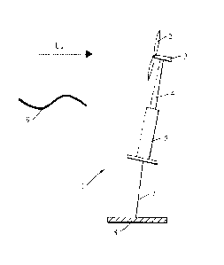
Turning first to Figure 5, there is illustrated a floating wind turbine
assembly 1.
It comprises a turbine rotor 2 mounted to a nacelle 3. The nacelle is in turn
mounted
to the top of a structure which comprises a tower 4 secured to the top of a
floating
body 5, which in the example shown is a spar-buoy like structure. The
disclosed
principles of controlling motions are applicable to all floating structures
for floating
wind turbines. The floating body is secured to the sea bed by one or more
anchor
lines 7 (only one is shown), these could be taut or catenary mooring lines.
The
nacelle contains an electrical generator which is connected to the turbine
rotor by any
known means such as a reduction gearbox, by direct connection to the
electrical
generator or hydraulic transmission etc (these items are not shown). The
nacelle
also contains a control unit.
The floating wind turbine is subject to incoming wind Uv, forces and wave 9
forces. (The waves 9 on the water's surface are shown schematically.) These
forces
will cause the floating wind turbine assembly 1 to move about in the water.
The control in the nacelle is arranged to determine a blade pitch adjustment
necessary to control the motions of the floating wind turbine. The controller
is further
arranged to adjust the blade pitch of each rotor blade independently so as to
create a
net force to control a motion of the floating wind turbine in an axial
direction, an in-
plane direction and a yaw direction.
CA 02895278 2015-06-16
WO 2014/096419 14
PCT/EP2013/077841
If the axial motion is to be damped in a frequency range close to the
resonance frequency wx , a force must be created that opposes the axial
velocity of
the rotor motion. If a dynamic and collective blade pitch motion is performed
at
frequency co. and amplitude Afi
0A an axial force (thrust) on the rotor opposing the
axial motion may be obtained. For a harmonic axial motion the blade pitch
angle
should be
/8 = + Apo Acos(co xt + ao)
[1]
Here A is the pitch angle that is set out by the conventional controller
aiming
for constant power production. AP
cos(wxt + a ) is the additional blade pitch angle
to achieve damping. ao is a phase angle between the axial velocity and the
maximum pitch angle and t is time.
If the in-plane motion is to be controlled in a frequency range close to the
resonance frequency for in-plane motion WY , a force must be created that
opposes
the in-plane velocity and/or the in-plane excursion of the rotor motion. If a
dynamic
blade pitch motion is performed giving an additional angle AP when passing the
top
position and a corresponding ¨AP when passing the lower position, a net in-
plane
force is obtained due to the changed lift forces on the blade. If this in-
plane force then
is varied with a frequency equal to the natural frequency of the in-plane
motion, a net
damping effect may be obtained. For a harmonic in-plane motion with frequency
WY
and a rotor frequency n the blade pitch of each of the blades should have an
individual pitch of the form:
AflYJ(t)=AflYAcos(wYt+aY)cos(t+OJ.O+7,)
[2]
In this example cosine harmonic functions are used to provide a smooth pitch
angle variation and thus smooth force variation. However, any smooth periodic
function with the prescribed frequency could be applied.
Here j is the blade number (j =1, 2 or 3 for a three bladed rotor), AflYA is
the
amplitude of the blade pitch angle, a y'7 Y are phases of the blade pitch
motion
CA 02895278 2015-06-16
WO 2014/096419 15
PCT/EP2013/077841
relative to the in-plane velocity and the top point position of the blade
respectively,
0 .
i is the phase corresponding to the initial position of each blade on the
rotor, i.e. for
a three bladed rotor 0] = 27r / 3 ( j ¨1) . aY can be varied so that the
force is either in
phase with the in-plane velocity (damping) or in phase with the in-plane
excursion
(restoring). For a harmonic oscillation these components have always a phase
difference of rc/ 2. The control may be tuned to both provide a restoring and
a
damping effect.
To generate a dynamic yaw moment, a similar principle as for the in-plane
motion may be used. The yaw natural frequency replaces the in-plane natural
frequency in [2], and the phases are changed to generate a yaw force rather
than an
in-plane force. Alternatively, the yaw frequency does not need to correspond
to the
yaw natural frequency and may also change over time. In the special case of
harmonic motion, this may be represented as
Af36, (t) = cos(coGt +a6)cos(S2t +60,0 +76)
[3]
76 is typically 21Y -1-7"/ 2 . As with the in-plane motion, the phase angle a6
may
be tuned to obtain an optimum balance between damping and restoring forces.
The total dynamic variation of the blade pitch angle will approximately be the
sum of the three individual components of AP above. The interaction effects
between the forces depend upon the relation between the natural frequencies
involved and the non-linearity in the lift and drag forces. A certain blade
pitch angle
will change the angle of attack close to the rotor axis more than close to the
tip. For
that reason an individual tuning of the contributions should be performed to
obtain
the wanted motion reduction and avoid as far as possible negative impacts as
reduced power production and increased blade loads. The above in-plane damper
and yaw motion control principles do not need to be activated continuously.
For
example, one may have a motion monitoring system that detects if the motions
(e.g.
displacements) exceed certain limits, i.e. a certain threshold, and then
activate the
control system accordingly.
If the in-plane (resonant) motion (roll) is excited by variation in the
aerodynamic or generator torque, an alternative control option is available:
That is to
modify the generator torque controller to impose damping in the relevant
frequency
interval. This can be achieved by modifying the original generator torque
control
CA 02895278 2015-06-16
WO 2014/096419 16
PCT/EP2013/077841
system to have an additional component in the generator torque reference
signal that
is proportional to the in-rotor plane tower velocity. For harmonic in-plane
motion the
generator torque reference can be formulated as
Tref = Tref 0 (1+ ATyA cos coyt),
[4]
AT
where ref is the original generator torque reference signal and i'A is the
relative amplitude of the additional torque control reference signal for
active in-plane
damping. This can be used in addition to the motion control which is achieved
by
pitching of the rotor blades or used on its own when it is desired to only
control the in-
plane motions.
The principle of desired blade pitch angle for generating an in-rotor-plane
harmonic force given in equation [2] can be applied to a control scheme with a
generally non-harmonic behaviour based on a measurement of the in-rotor-plane
velocity of a floating wind turbine.
Consider a measurement of the in-rotor-plane horizontal velocity 5'n ,
measured at the nacelle level. Then, an active in-plane damping control scheme
can
be formulated as
ref ,i = c fir [5]
where fi ref 'I is the blade pitch angle reference signal for blade i , eis
the
collective blade pitch angle reference signal for all blades (including
possibly active
pitch motion damping control), while fir is the additional in-plane individual
blade
pitch angle reference for blade i which is controlled to give an in-rotor
plane damping
force by the equation:
K 5,5 cos(0), [6]
where Kw is the in-plane damping controller gain and 01 is the azimuth angle
of blade i. It is often desired to provide additional damping at the natural
frequency
of the in-plane motion, and to consider higher frequencies like the wave
frequencies
as undesired disturbance. It can therefore be advantageous to use a low pass
filter
CA 02895278 2015-06-16
WO 2014/096419 17
PCT/EP2013/077841
on the in-rotor-plane horizontal velocity 5).. In Laplace form a second order
Butterworth filtering of 5 ) can be represented as
co,2
5)nf (S) s2 + Nrico,s +,n CO
[7]
where c , is the cut-off frequency in the low pass filter and i'rif is the
filtered
nacelle velocity. An in-rotor-plane control scheme with low pass filtering can
then be
by formulated by combining equation [6] and equation [7]:
ph. = Kõ,.5),/ cos(07.) [8]
The active in-plane damping by use of individual blade pitch control can be
applied both above and below the rated wind speed. The measured in-rotor-plane
velocity could be measured directly or could be an estimate based on other
measurements. A simulation snapshot plot with and without active in-plane
damping
with use of individual blade pitch control is shown in Figure 1. Figure 1
shows a time
domain simulation snapshot plot of the in-plane motion for an environmental
condition with significant wave height 5 m, peak period 10.7 sand mean wind
speed
16.5 m/s. Conventional floating wind turbine collective blade pitch control
system
(ADC) and conventional system with active in-plane damping by use of
individual
blade pitch control (ADC + ARIC) are shown. The simulations are carried out
with
27c
ct)c
measurement of the nacelle sway velocity, Kw -= ¨0.25 and = LV . The
natural
period in roll in this case is 30 seconds. A significant reduction in the in-
plane motion
is observed by applying ARIC, even if the parameter setting is not optimized.
Due to the nonlinear nature of the aerodynamic forces on the rotor blades, it
may be advantageous to apply gain scheduling techniques to schedule the in-
plane
damping controller gain with the operational condition based on measurements
of
e.g. rotor speed, blade pitch angle and/or wind speed.
As mentioned above, an alternative method for damping of the in-rotor-plane
motions of a floating wind turbine is to add an additional signal proportional
to the in-
rotor-plane horizontal tower velocity to the generator torque reference
signal, ref .
CA 02895278 2015-06-16
WO 2014/096419 18 PCT/EP2013/077841
Consider a measurement of the in-rotor-plane horizontal velocity ,
measured at the nacelle level. Then, an active in-plane damping control scheme
can
be formulated as:
Tref = Tref 0(1+ K )n), [9]
where t'ef is the original generator torque reference signal, and K
te is the in-
plane damping generator torque controller gain.
Similarly as in the previous section, an in-rotor-plane control scheme with
low
pass filtering can be desirable to avoid high frequency disturbances and use
of the
low pass filtering scheme in equation (8) leads to the following generator
torque
control scheme for active in-plane damping:
Tref = Tel 0 0 + K tc.)') nf) [10]
The active in-plane damping by use of generator torque control is particularly
suitable below the rated wind speed and the measured in-rotor-plane velocity
could
also be an estimate based on other measurements. A simulation snapshot plot
with
and without active in-plane damping with use generator torque control below
the
rated wind speed is shown in Figure 2. Figure 2 shows a time domain simulation
snapshot plot of the in-plane motion at the mean water level for an
environmental
condition with significant wave height 2 m, peak period 8.5 s and mean wind
speed 8
m/s. Conventional wind turbine control system (CC) and conventional system
with
active in-plane damping by use of generator torque control (CC + ARTC) are
shown.
The simulation is carried out with measurement of the nacelle sway velocity,
25.
co, =
K = 3.0 and 20
The principle of desired blade pitch angle for generating a yaw harmonic force
given in equation [3] can be transferred to a control scheme with a generally
non-
harmonic behaviour based on a measurement of the yaw velocity of the floating
wind
turbine. However, it is desirable to include proportional and/or integral
control actions
in addition to, or instead of, the derivative control actions indicated in
equation [3].
This because the yaw motions are slowly varying and because the yaw motions
are
little affected by the waves.
CA 02895278 2015-06-16
WO 2014/096419 19
PCT/EP2013/077841
Figure 3 shows the rotational angle of the blades as seen in the positive x-
direction (wind direction). From Figure 3 it can be seen that a restoring yaw
moment
for a positive yaw motion is obtained by positive individual pitching of the
rotor blades
with rotor blade azimuth angles from 0 to 180 degrees and negative individual
pitching of the rotor blades with rotor blade azimuth angles from 180 to 360
degrees,
and opposite for negative yaw motion.
It is assumed that a smooth cyclic variation of the rotor blade pitch angles
are
desirable during one revolution of the rotor, and on this basis a control
schedule
incorporating proportional, integral, and derivative yaw motion control
actions can be
formulated as:
ref ,1 = A+ Pry, [11]
where fi ref is the blade pitch angle reference signal for blade i , Pc is the
collective blade pitch angle reference signal for all blades (including
possibly active
pitch motion damping control), while 181Y is the additional yaw individual
blade pitch
angle reference for blade i , represented as
= (KO + K iy5 0(r)di- + K0yd)sin(0;),
to [12]
where 0 is the tower yaw angle, 0 is the tower yaw angular velocity, I CiY is
the integral controller gain, KPY is the proportional controller gain and KvY
is the
derivative controller gain and Cbi is the azimuth angle of rotor blade i=
The active yaw motion control by use of individual blade pitch control can be
applied both above and below the rated wind speed. The yaw motion may be
measured directly or could also be an estimate based on other measurements. A
simulation snapshot plot with and without active yaw motion control with use
of
individual blade pitch control is shown in Figure 4. Figure 4 shows a time
domain
simulation snapshot plot of the yaw motion at the mean water level for an
environmental condition with significant wave height 5 m, peak period 10.7 s
and
mean wind speed 16.5 m/s, i.e. above rated wind speed. Conventional floating
wind
turbine collective blade pitch control system (ADC) and conventional system
with yaw
motion control by use of individual blade pitch control (ADC + AYIC) are
shown. The
K =2.5 K. =0.25 K =0
simulation is carried out with PY Y and v-v .
CA 02895278 2015-06-16
WO 2014/096419 20
PCT/EP2013/077841
In this example the derivative controller gain is set to zero. This is because
it
was realised that the effect of the derivative controller action on yaw
motions in
floating wind turbines is negligible. The yaw motion is slowly varying with
changes in
the wind field so, as a result, a damping force (provided by the derivate
control
action) has little effect. As a result the controller does not need to
comprise a
derivative control action.
Due to the nonlinear nature of the aerodynamic thrust force, it may be
advantageous to apply gain scheduling techniques to schedule the yaw motion
controller gains with the actual operational condition based on measurements
of e.g.
rotor speed, blade pitch angle and/or wind speed.
The control schemes presented above for the in-plane motion (either by blade
control or torque control) can be combined (multiplied by suitable scaling
factors and
added together) with the control schemes for yaw motion to obtain both active
in-
plane damping and yaw motion control. The control schemes above are examples
on
implementation only and are not optimized. Optimization will employ controller
settings that reduce the motions sufficiently and at the same time do not
cause too
large negative effects on e.g. blade loads.