Note: Descriptions are shown in the official language in which they were submitted.
CA 02895379 2015-06-16
WO 2014/105732 PCT/US2013/077067
1
Cartridge Assembly for an Injection System
CROSS-REFERENCE TO RELATED APPLICATION
[0001] This application claims the benefit of U.S. Provisional Application
No. 61/747,483,
filed December 31, 2012.
FIELD OF THE INVENTION
[0002] The invention relates generally to injection systems for delivering
a pharmaceutical
product to a patient, and more particularly to cartridge assemblies for use
with injection systems.
BACKGROUND OF THE INVENTION
[0003] Pharmaceutical products are often delivered or transferred through
the use of an
injection system, such as a reusable syringe system. Instead of being provided
directly in the
injection system, however, many pharmaceutical products in the market today
are provided in a
cartridge assembly that can be loaded into the injection system. Once loaded,
a medical
professional can activate the cartridge assembly and deliver the
pharmaceutical product to the
patient.
100041 These cartridge assemblies typically include an ampule containing
the pharmaceutical
product and a hub. The ampule is typically closed at the proximal end with a
flexible piston, and
closed at the distal end with a pierceable diaphragm. The distal end is also
conventionally fitted
with the hub.
[0005] The hub typically features a metal piercing member at its proximal
end for piercing
the diaphragm of the ampule during activation of the cartridge assembly in
order to access the
pharmaceutical product and allow for its delivery through a delivery device
connected to the
=
2
distal end of the hub. The delivery device can take many forms. For example,
it may include a
needle of known construction, thereby enabling direct or indirect delivery of
a pharmaceutical
product to a patient (e.g., through intravenous injection or through a septum
that fluidly seals a
port associated with a tube set that is, or can be, fluidly connected to a
patient). Alternatively,
the delivery device can be a blunt needle that is constructed to be inserted
through a pre-pierced
septum of a tube set. In other instances, the delivery device can be a luer
fitment (male or
female, locking or not-locking) configured to mate with a complementary luer
fitment of another
delivery device.
[00061
Examples of known injection systems for use in combination with a cartridge
assembly include the CARPUJECT and iSecureTM systems, both of which are
currently owned,
marketed, and sold by Hospira, Inc. (Lake Forest, Illinois), the assignee of
this application and
the inventions disclosed herein. Various aspects of these systems are
described in U.S. Patent
Nos. 5,653,698 and 7;563,253.
While the systems that use metal cannulas for piercing a diaphragm associated
with an
ampule perform as intended, the inventors have identified an opportunity
replace the metal
cannula in order to achieve a more cost efficient design.
CA 2895379 2020-03-24
CA 02895379 2015-06-16
WO 2014/105732 PCT/US2013/077067
3
SUMMARY
[0007] In one aspect, the invention is directed to a cartridge assembly for
use with an
injection system. The cartridge assembly may include an ampule containing a
pharmaceutical
product that is sealed at a distal end with a pierceable diaphragm. The
cartridge assembly may
also include a hub comprising a proximal portion defining a cavity that is
configured to engage
the distal end of the ampule and a piercing member positioned within the
cavity. The piercing
member may include a fluid pathway between a proximal end portion comprising
an opening and
a distal end in fluid communication with a distal opening of the hub. The
proximal end portion
may engage the pierceable diaphragm. The hub may be configured to engage the
ampule in an
inactivated position in which the piercing member is not in fluid
communication with the
pharmaceutical product in the ampule and an activated position in which the
proximal end
portion of the piercing member is in fluid communication with the
pharmaceutical product in the
ampule. Further, the piercing member may apply a force to the pierceable
diaphragm in the
inactivated position without penetrating the pierceable diaphragm.
[0008] In another aspect, the invention is directed to a method for
providing a sterilized
cartridge assembly for use with an injection system. The method may include
providing a sealed
ampule containing a pharmaceutical product and having a pierceable diaphragm.
The method
may also include providing a hub comprising a plastic piercing member for
piercing the
diaphragm. The method may also include connecting the ampule to the hub to
create the
cartridge assembly without causing the piercing member to pierce the ampule.
The method may
also include autoclaving the cartridge assembly.
[0009] These as well as other aspects, advantages, and alternatives will
become apparent to
those of ordinary skill in the art by reading the following detailed
description with reference
CA 02895379 2015-06-16
WO 2014/105732 PCT/US2013/077067
4
where appropriate to the accompanying drawings. Further, it should be
understood that the
description provided in this summary section and elsewhere in this document is
intended to
illustrate the claimed subject matter by way of example and not by way of
limitation.
CA 02895379 2015-06-16
WO 2014/105732 PCT/US2013/077067
BRIEF DESCRIPTION OF THE DRAWINGS
[0010] Figure lA is an exploded view of a cartridge holder used in
conjunction with a
cartridge assembly;
100111 Figure 1B is a plan view of a cartridge assembly for use with a
cartridge holder;
[0012] Figure 2A is a plan view of a distal end of an ampule;
[0013] Figure 2B is a cross section view of a hub in an inactivated
position;
[0014] Figure 2C is a cross section view of a hub in an activated position;
[0015] Figure 2D is a plan view of a piercing member;
[0016] Figure 2E is a plan view of a hub;
[0017] Figure 3 is a side view of an example of a piercing member;
[0018] Figure 4 is a side view of another example of a piercing member; and
[0019] Figures 5A and 5B are cross sectional views of the distal end of an
ampule with a
protective sheath configured for autoclave sterilization (5A) and sterile
packaging (5B).
CA 02895379 2015-06-16
WO 2014/105732 PCT/US2013/077067
6
DETAILED DESCRIPTION
[0020] In general, the invention is directed to a medication delivery
device including a
cartridge assembly having an ampule containing a medication and a pierceable
seal. The device
also includes a piercing member for piercing the seal and accessing the
medication. The device
can be sterilized by autoclave sterilization. The cartridge can use used in a
conjunction with a
reusable cartridge holder that allows for a medical professional to deliver
medication from the
ampule to the patient in a sterile manner.
[0021] As used herein, the terms "distal," "lower," and "downward" are
intended to
reference the end of the cartridge holder or components thereof, which would
be furthest from
the medical professional holding the cartridge holder during use. Conversely,
the terms
"proximal," "upper," and "upward" are intended to reference the end of the
cartridge holder or
components thereof, which would be nearest the medical professional during
use.
[0022] Figures lA and 1B shows an exemplary cartridge assembly 100 and an
exemplary
cartridge holder 102 for use therewith. The cartridge assembly 100 can be
provided separately
from the cartridge holder 102 such that a medical professional (e.g., a
pharmacist or nurse)
inserts the cartridge assembly 100 into the cartridge holder 102 prior to use.
Alternatively, the
cartridge assembly 100 and cartridge holder 102 can be pre-assembled by a
manufacturer or
assembler and supplied in combination to medical professionals.
[0023] The cartridge assembly 100 of the present invention can have a
variety of
configurations. In one embodiment, the cartridge assembly 100 includes an
ampule 104
configured to retain a liquid pharmaceutical product. The ampule 104 can be
constructed from
known glass materials due to the relative inactivity between glass and most
pharmaceutical
CA 02895379 2015-06-16
WO 2014/105732 PCT/US2013/077067
7
products. However, it will be appreciated that in certain cases it may be
appropriate or necessary
to use non-glass materials due to the possible interaction between the
pharmaceutical product
and glass.
100241 The proximal end of the ampule 104 is fluidly sealed with a flexible
piston 106 that is
configured to slide axially within the ampule 104 in order to discharge the
medication from the
ampule 104. The proximal side of the piston 106 is provided with a connecting
member 108 that
it is accessible from the exterior of the ampule 104. The connecting member
108 can have a
variety of configurations, including that of a threaded rod constructed to
engage complementary
threads (not shown) on a plunger rod 110 of the cartridge holder 102.
Alternatively, the
connecting member 108 can be constructed to provide a snap fit with a
complementary
connecting member (not shown) on the plunger rod 110. Those skilled in the art
will appreciate
that the connecting member 108 can have other configurations providing locking
or frictional
connections with the plunger rod 110.
[0025] As shown in Figure 2A, the distal end 132 of the ampule 104 is
fluidly sealed by a
pierceable seal, such as diaphragm 112. The seal, such as diaphragm 112, can
be constructed of
a variety of known materials, including elastomeric materials that do not core
when a piercing
member is passed therethrough. Accordingly, the seal, once punctured, should
create a fluid seal
around the piercing member. The seal may be held in place by any means known
to those of
skill in the art, including a metal end cap at the distal end 132 of the
ampule. Just proximal to
the distal end of the ampule is a neck-down portion 131.
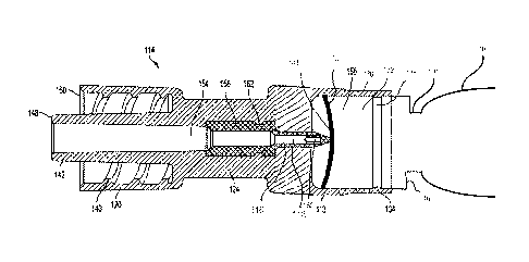
[0026] As shown in Fig. 2B, a plastic hub 114 has a proximal portion with
an open-ended,
sleeve-like cavity 130 defined by circumferential wall 113 and a distal
portion defining a
CA 02895379 2015-06-16
WO 2014/105732 PCT/US2013/077067
8
connecting portion 120. Cavity 130 is slidably mounted with the distal end 132
of the ampule.
The hub 114 includes plastic piercing member (or cannula) 116 that is axially-
mounted within
the cavity and that is configured to penetrate the diaphragm 112 during
activation of the cartridge
assembly 100. Activation occurs when the distal end of the ampule 104 moves in
the distal
direction within the cavity 114, thereby causing the piercing member 116 to
penetrate the
diaphragm 112.
[0027] The entire hub 114, including the piercing member 116, may be
constructed of a
single plastic material. Alternatively, the piercing member 116 may be
constructed of a different
plastic material than the remainder of the hub 114. For example, the piercing
member 116 may
be constructed of polymethyl methacrylate, a polycarbonate, polyethylene
terephthalate glycol
(PETG), or an impact modified acrylic based multipolymer. The rest of the hub
114 may be
constructed of, for example, polypropylene or a polyethylene based polymer
(e.g., LDPE,
HDPE, LLDPE). In addition, additives may be added to the plastic(s) to reduce
the coefficient
of friction between the components of the hub 114 and components of the ampule
104, for
example, between the piercing member 116 and the diaphragm 112. As one
example. the
piercing member may be constructed of a polycarbonate with a silicone
additive. In one
embodiment, the polymers for the hub and piercing member have a tensile
strength of greater
than 4500 psi (31MPa).
[0028] The piercing member 116 may be molded (e.g., injection molded)
separately from the
rest of the hub 114. In such an embodiment, the piercing member 116 may be
press fit into the
bore of the hub 114 and/or be affixed thereto using any known connection means
in the art
including an adhesive, threaded engagement, weld, snap fit, etc.
Alternatively, the hub 114 may
be manufactured using a two-shot injection molding process. In one example,
the piercing
CA 02895379 2015-06-16
WO 2014/105732 PCT/US2013/077067
9
member 116 is molded first and then the rest of the hub 114 is overmolded onto
the piercing
member 116. In another example, the hub 114 is molded first and then the
piercing member 116
is overmolded onto the hub 114.
[0029] In one example, the piercing member 116 may include a necked down
portion 162
(see Figure 2B) of the piercing member 116, which results in a tongue and
groove connection
that prevents the piercing member 116 from moving axially relative to the rest
of the hub 114. In
another example, the piecing member 116 may include one or more protrusions
151A-E that are
configured to fit into one or more holes 153A-D in a necked-down portion 124
of the hub 114
(see Figures 2D-2E). The one or more protrusions fit within the one or more
holes prevent the
piercing member 116 from moving axially relative to the rest of the hub 114.
100301 The hub 114 is slidable relative to the distal end 132 of the ampule
104 between a
first, inactivated position in which the piercing member 116 engages but does
not pierce the
diaphragm 112 (as shown in Figure 2B), and a second, activated position in
which the piercing
member 116 is inserted through the diaphragm 112 (as shown in Figure 2C). In
the activated
position, an interior lumen 118 of the piercing member 116 is in fluid
communication with the
pharmaceutical product in the cavity of ampule 104. Thus, in the activated
position, a fluid
pathway is provided for the egress of the pharmaceutical product from the
ampule 104 through
the lumen of 118 of the piercing member 116 to the connecting portion 120 of
the hub 114.
When pressure is applied to piston 106, fluid is forced through the fluid
pathway.
[0031] The distal portion 148 of the hub 114 includes a connecting portion
120 that is
configured to deliver the pharmaceutical product contained in the ampule 104
directly to a
patient or to another medical delivery device (e.g., a tube set configured to
deliver
CA 02895379 2015-06-16
WO 2014/105732 PCT/US2013/077067
pharmaceutical products to a patient). As shown in Figures 1B and 2B-2C, the
connecting
portion 120 may include a threaded luer member constructed to connect with a
complementary
luer member on a separate delivery device (not shown). It will be appreciated
that the delivery
device can have a variety of configurations, including, for example, (i) a
hypodermic needle for
delivery of pharmaceutical products directly to a patient or for indirect
delivery through a
pierceable septum (e.g., a pierceable septum associated with an add port of a
tube set or an add
port of a flexible pharmaceutical container), (ii) a blunt needle for delivery
of pharmaceutical
products to another medical device having the capability of receiving a
pharmaceutical product
from a blunt needle (e.g., a pre-slit elastomeric seal on a tube set or a
flexible pharmaceutical
container), (iii) threaded luer; and/or (iv) an unthreaded luer. Although the
connecting portion
120 is described as being configured to connect to a variety of separate
delivery devices, in other
embodiments, a delivery device may be integrated into the connecting portion
120 of the hub
114. For example, instead of being a threaded luer member that can connect to
a blunt needle, a
blunt needle may be integrated into the connecting portion 120 of the hub 114.
To ensure
sterility of the cartridge assembly 100 prior to use, a cap member (not shown)
may be provided
in order to cover the connecting portion 120.
100321 The hub 114 includes a necked-down portion 124 that is constructed
to be positioned
within a retention feature 127 of the cartridge holder 102 during use. When
the cartridge
assembly 100 is loaded into the injector body 126 of the cartridge holder 102,
and the necked-
down portion 124 is secured within the retention feature 127, the hub 114 is
precluded from
moving distally. Thus, a medical professional can activate the cartridge
assembly 100 by
manipulating (e.g., rotating) a locking member 128 in order to advance the
ampule in the distal
direction and apply a distally-directed force to the proximal end of the
ampule 104. Because the
CA 02895379 2015-06-16
WO 2014/105732 PCT/US2013/077067
11
hub 114 is precluded from moving distally, the application of a distally-
directed force on the
proximal end of ampule 104 causes the distal portion of the ampule 132 to
slide axially within
the cavity of the proximal portion of the hub 114, thereby transitioning the
cartridge
assembly 100 from its first, inactivated position to its second, activated
position in which the
piercing member 116 of the hub 114 penetrates the diaphragm 112 of the ampule
104 and places
the lumen 118 of the piercing member 116 in fluid communication with the
pharmaceutical
product.
[0033] After the plunger rod 110 has been connected to the connecting
portion 108 of the
piston 106, the pharmaceutical product contained in the ampule 104 can be
delivered to a patient
or transferred to another medical device by the application of a distally-
directed force to plunger
rod 110. If desired, fluids can be aspirated into the ampule 104 at any time
through the
application of a proximally directed force to plunger rod 110.
[0034] As shown in Figure 2B, the hub 114 generally includes a proximal
portion 130 and a
connecting portion 120, connected by a necked-down portion 124. The piercing
member 116 is
axially located within the cavity of the proximal portion 130 of the hub 114.
As noted above, the
piercing member 116 is configured to pierce the diaphragm 112 of the ampule
104 during
activation of the cartridge assembly 114 (i.e., when the hub 114 and ampule
104 are brought
together) and thereby access the pharmaceutical product in the ampule 104. The
proximal
portion 130 is also configured to receive and engage the distal end portion
132 of the ampule
104. In one embodiment, the cavity of the proximal portion 130 has a radially
inwardly facing
annular bead 134. As shown in Figure 2B, when the cartridge assembly 100 is in
the inactivated
position, the bead 134 engages an annular groove 138 on the distal end portion
132 of the ampule
104. This snap-type engagement helps maintain sterility of the piercing member
116 by
CA 02895379 2015-06-16
WO 2014/105732 PCT/US2013/077067
12
preventing access thereto, and helps minimize or eliminate pre-mature
activation of the cartridge
assembly 100 by increasing the force required to move the hub 114 and ampule
104 toward one
another.
100351 As noted above, the connecting portion 120 of the hub 114 is
configured to receive
and engage a separate delivery device (not shown) for directly or indirectly
delivering the
pharmaceutical product from the cavity of the ampule 104 to the patient. In
the embodiments
disclosed herein, the connecting portion 120 includes a collar 150 having
radially inwardly
facing threads 140 and a centrally located male luer 142. As such, the
connecting portion 120 is
designed as a male luer-locking fitment configured to mate with a
complementary female luer
fitment of a delivery device. Although shown and described herein as a male
luer-locking
fitment, the distal connecting portion 120 may not include a locking feature,
and moreover, may
be replaced with a female luer fitment (locking or not-locking) configured to
mate with a male
luer fitment of a delivery member.
100361 When the cartridge assembly 100 is in the inactivated position, as
shown best in
Figure 2B, the piercing member 116 engages the diaphragm 112 and applies a
force that pushes
the center of the diaphragm away from its resting plane (i.e., the planar
surface when no force is
applied). The force applied by the piercing member 116 to the diaphragm 112 is
maintained by
the friction between the annular bead 134 and the annular groove 138 (as best
shown in Figure
2B). In one embodiment, the amount of distance that the piercing member
proximally displaces
the center of the diaphragm is about 0.040 inches, which reflects the amount
of distance that the
piercing member pushes the center of the diaphragm out of its resting plane.
CA 02895379 2015-06-16
WO 2014/105732 PCT/US2013/077067
13
[0037] Although the piercing member 116 applies a force to the diaphragm
112 in the
inactivated position, the geometry and material properties of the piercing
member 116 prevent
the piercing member 116 from penetrating the diaphragm 112 prior to activation
of the cartridge
assembly 100. In other words, the force required to penetrate the diaphragm
112 is greater than
the force applied by the piercing member 116 on the diaphragm 112 in the
inactivated position.
[0038] When the ampule 104 and hub 114 are activated, the wall 113 defining
the cavity of
the proximal portion 130 of the hub 114 slides over the distal end portion 132
of the ampule 104
from the inactivated position (in which there is no fluid communication
between the piercing
member 116 and the pharmaceutical product) to the activated position shown in
Figure 2C, in
which the piercing member 116 is in fluid communication with the
pharmaceutical product in the
cavity of the ampule 104. The force required to activate the cartridge
assembly 100 can vary
depending on design but is preferably less than 12 lbf. In one embodiment, the
force required for
activation is between 5-12 lbf. The force required for activation should be
achievable by most
medical professionals. Various factors can affect the required activation
force including, for
example, the hoop strength of the annular bead 134, the geometry and material
properties of the
piercing member 116, and the geometry and material properties of the
pierceable diaphragm 112.
100391 Once the cartridge assembly 100 is in the activated position, the
annular bead 134 no
longer engages the groove 138 on the distal portion 132 of the ampule 104.
Instead, the annular
bead 134 moves proximally with respect to the distal portion 132 of the ampule
104. Similarly,
the annular groove 138 moves distally with respect to the proximal end 130 of
the hub 114. The
axial displacement of the bead 134 and annular groove 138 can vary. In one
embodiment, after
activation the bead 134 abuts a shoulder 146 at a neck-down portion 131 near
the distal
portion 132 of the ampule 104. Because the inner diameter of the bead 134 is
less than the outer
CA 02895379 2015-06-16
WO 2014/105732 PCT/US2013/077067
14
diameter of the neck down portion 131, the hub 114 is prevented from moving
back in the distal
direction after activation. This helps to ensure that the cartridge assembly
100 remains in the
activated position until all of the pharmaceutical product is delivered to the
patient. Moreover,
this helps prevent pharmaceutical product from escaping into the environment
do to
disengagement between the ampule 104 and hub 114.
[0040] As shown in Figures 2B-2D, 3, and 4, the piercing member 116
generally comprises
(i) a tip portion 156 for piercing and penetrating the diaphragm 112 of the
ampule 104 and (ii) a
base portion 158 for mounting the piercing member 116 within the bore of the
hub 114. The tip
portion 156 is provided with at least one opening 160 near the tip 144. The
number of openings
can vary depending on design. In the embodiments disclosed herein, the
piercing member 116
has two openings 160.
100411 Figures 3 and 4 show two different embodiments for the geometry of
the tip
portion 156 of the piercing member 116. In both embodiments, the tip portion
156 includes two
openings 160, spaced 180 degrees apart. As shown, the openings 160 are
generally rectangular
in cross section and elongated axially. However, in other embodiments, there
may be any
number of openings 160 equally or arbitrarily spaced from one another.
Moreover, the openings
160 need not be identical and can vary.
[0042] As shown, the tip 144 of the piercing member 116 is generally
triangular in cross
section and intentionally blunt. This is in stark contrast to a traditional
metal piercing member,
which is very small in diameter and extremely sharp. The bluntness of the
piercing member 116
helps to ensure that the piercing member 116 does not pre-maturely pierce the
diaphragm 112
CA 02895379 2015-06-16
WO 2014/105732 PCT/US2013/077067
when the cartridge assembly 100 is in the inactivated position and the
piercing member 116
engages the diaphragm 112.
[0043] As the cartridge assembly 100 is activated, the tip 144 of the
piercing member 116 is
forced through the pierceable diaphragm 112 until the openings 160 are in
fluid communication
with the pharmaceutical product. To increase the amount of flow through the
openings 160, the
piercing member 116 is designed such that in the activated position the
openings 160 are entirely
open to the pharmaceutical product.
100441 In the inactivated position, the piercing member 116 exerts a force
on the diagram
112 that moves the surface of the diaphragm out of its resting planar
position. Also, due to the
geometry of the piercing member 116, and the friction between the piercing
member 116 and the
diaphragm 112, the planar surface of the diaphragm 112 is further forced away
from the resting
plane during activation. Despite the resilient properties of the diaphragm
112, the diaphragm
112 tends to remain in a proximally flexed position even after activation (a
"trampoline effect").
This is in contrast to a typical cartridge assembly wherein the sharp and
narrow geometry of a
metal piercing member causes little or no proximal displacement of the plane
of the diaphragm
112 during and/or after activation.
[0045] The plastic cannula is understood to cause a blunt tear of the
diaphragm upon
activation instead of a piercing/cutting effect associated with a sharp metal
piercing member.
The trampoline effect can be minimized by elongating opening 160 to reduce the
contact area
and friction between the diaphragm 112 and piercing member 116 (see Figs. 3
and 4). In
addition, as shown in Figure 4, distal end of the opening 160 include radial
chamfers 164, which
help to avoid the diaphragm 112 from catching on the corner of the opening
160.
CA 02895379 2015-06-16
WO 2014/105732 PCT/US2013/077067
16
[0046] The trampoline effect caused by the geometry and material properties
of the plastic
piercing member 116 and diaphragm 112 means that the amount of axial
translation between the
hub 114 and ampule 104 (measured from contact between the piercing member 116
and the
diaphragm 112 in its resting planar position) in order to activate the
cartridge assembly 100 is
greater than that required to activate a traditional cartridge assembly with a
metal piercing
member that does not cause such a trampoline effect. To compensate for this
additionally
required axial movement, the hub 114 is configured such that the piercing
member 116
proximally displaces with the diaphragm 112 in the inactivated position. By
designing the
hub 116 in this manner, the distance of the axial movement that the cartridge
holder 102 must
move ampule 104 is the same as an ampule with a hub having a traditional metal
piercing
member. This allows the hub 114 with the plastic piercing member 116 to be
used with existing
cartridge holders that are limited in the amount of axial translation between
the hub and ampule.
[0047] As best shown in Figure 2B, the distal end 148 of the male luer 142
extends past a
collar 150 of the distal connecting portion 120. In other embodiments,
however, the distal end
148 of the luer 142 may be co-planer with the distal end of the collar 150 of
the connecting
portion 120 or may even terminate below the collar 150. The necked-down
portion 124
connecting the proximal portion 130 and the distal connecting portion 120
includes four radially
extending fins 152 that are evenly spaced around the circumference of the
necked-down portion
124. These fins 152 help increase the structural integrity of the hub 114.
Other embodiments of
the hub 114 may include a different number of fins 152. As best shown in
Figure 2B, a fluid
path 154 passes through the entire hub 114. The proximal portion of the fluid
path 154 is
defined by the lumen 118 of the piercing member 116.
CA 02895379 2015-06-16
WO 2014/105732 PCT/US2013/077067
17
[0048] It is important that the cartridge assembly 100 is provided to the
medical professional
in a sterile condition. The hub 114 and ampule 104 may be provided to medical
professionals as
separate pieces that have been sterilized independently or as a single
cartridge assembly 100,
with the hub 114 and ampule 104 being sterilized and then assembled in a
sterile environment or
assembled and then sterilized together.
[0049] In one aspect, the ampules and injector systems by autoclaving,
which typically uses
a high pressure steam environment at about 121 degrees Celsius for at least
about 15 minutes.
While the autoclaving process is useful for sterilizing cartridge assemblies,
the heat associated
with the autoclaving process can cause the diaphragm 112 of the ampule 104 to
expand distally
due to an increase in pressure within the ampule 104. In traditional cartridge
assemblies with a
metal piercing member, this distal expansion can cause premature piercing of
the diaphragm. In
addition to premature piercing, the heat associated with the autoclaving
process may cause the
metal piercing member to get so hot that it softens the plastic of the
surrounding hub, which may
result in the metal piercing member shifting within the plastic hub.
[0050] These problems associated with traditional cartridge assemblies are
reduced or
eliminated in the cartridge assembly 100 disclosed herein, which has a plastic
piercing
member 116. The plastic piercing member 116 is designed to interfere with the
diaphragm 112
of the ampule 104 without penetrating the diaphragm and will not transfer heat
to the
surrounding components.
[0051] In addition, as shown in Figures 5A and 5B, in order to accommodate
the autoclave
sterilization of the ampule and maintain the sterility of the luer member 142
of the connecting
portion 120, the luer member 142 may be fitted with a sheath 172, which
includes plug 170. Fig.
CA 02895379 2015-06-16
WO 2014/105732 PCT/US2013/077067
18
5A shows the luer member 142 and sheath 172 in condition for autoclave
sterilization. Fig. 5B
shows the luer 142 and sheath 172 in condition for sterile packaging following
autoclave
sterilization. Sheath 172 includes sidewall 174 that fits snugly, but
removably, between the luer
member 142 and the threads 140 of the collar 150. The plug 170 fits through an
opening 176 at
the distal end of the sheath 172. The plug 170 includes a proximal portion 178
having an outer
circumference that fits within the inner diameter of male luer 142. The outer
circumference of
the proximal portion 178 includes one or more interrupted portion(s) 180 that,
curing autoclave
sterilization, provide a venting with the interior of the male luer 142. As
shown in Fig. 5A,
detent 182 of the plug 170 maintains the plug 170 in a fixed position during
autoclaving by
engaging indent 184 of the sheath 172.
[0052] As shown in Fig. 5B, following the autoclaving process, the plug 170
is moved
proximally into the opening 176 of the sheath 172 causing a central portion
186 of the plug 180
to move into the male luer 142. The central portion has an uninterrupted outer
circumference,
which sealingly engages the interior diameter of the male luer 142. The detent
182 is moved out
of indent 184 and the male luer 142 is maintained in a sterile condition. The
sheath 172 and the
plug 170 are removed when they are to be connected to the appropriate fitting
for delivery of the
contents of ampule 100 to a patient. The sheath 170 and the plug 142 can be
constructed of rigid
or resilient plastic materials suitable for pharmaceutical applications.
Dimensional interference
between the sidewall 174, the threads 140 and the male luer 142, and between
the outer
circumference of central portion 186 and the interior diameter of the male
luer provide for
sealing but removeable engagement between the sheath 172, the plug 170 and the
male luer 142.
[0053] Accordingly, in one aspect, the disclosure is directed to a method
of providing a
sterile cartridge assembly 100 for use in an injection system, for example for
use with cartridge
CA 02895379 2015-06-16
WO 2014/105732 PCT/US2013/077067
19
holder 102. The method may include: (i) providing a sealed ampule 104
containing a
pharmaceutical product; (ii) providing a hub 114 comprising a plastic piercing
member 116; (iii)
connecting the ampule 104 to the hub 114 to create the cartridge assembly 100
without
penetrating the diaphragm 112 of the ampule 104; and (iv) sterilizing the
cartridge assembly 100
with an autoclaving process. During the autoclaving process, the plastic
piercing member 116
will not penetrate the diaphragm 112. In addition, the assembly of the ampule
and hub prior to
sterilization may allow for the plastic piercing member 116 to apply force to
the diaphragm 112
without piercing the diaphragm 112. Even in this preloaded condition, the
piercing member 116
will not pierce the diaphragm 112 during the autoclaving process. Moreover,
use of the plastic
piercing member 116 avoids deformation of the structure in the hub 114
supporting the piercing
member 116 during autoclaving.
[0054] Various examples of a cartridge assembly and corresponding method of
providing a
cartridge assembly for use with an injection system have been described above.
Those skilled in
the art will understand, however, that changes and modifications may be made
to those examples
without departing from the scope of the claims.