Note: Descriptions are shown in the official language in which they were submitted.
CA 02895860 2015-06-29
METHOD FOR GENERATING A DIAGNOSTIC FROM A DEVIATION OF A
FLOW METER PARAMETER
The present application is a divisional application of Canadian Patent
Application No.
2,722,856 filed on January 5, 2008.
TECHNICAL FIELD
The present invention relates to flow meters, and more particularly, to a
method for
generating a diagnostic using a deviation in a flow meter parameter.
BACKGROUND OF THE INVENTION
It is generally known to use Coriolis effect mass flow meters to measure mass
flow
and other information for materials flowing through a conduit in the flow
meter. Exemplary
Coriolis flow meters are disclosed in U.S. Patent 4,109,524, U.S. Patent
4,491,025, and Re.
31,450 all to J.E. Smith et al. These flow meters have one or more conduits of
straight or
curved configuration. Each conduit configuration in a Coriolis mass flow meter
has a set of
natural vibration modes, which may be of simple bending, torsional, or coupled
type. Each
conduit can be driven to oscillate at resonance in one of these natural modes.
Material flows
into the flow meter from a connected pipeline on the inlet side of the flow
meter, is directed
through the conduit or conduits, and exits the flow meter through the outlet
side of the flow
meter. The natural vibration modes of the vibrating, material filled system
are defined in
part by the combined mass of the conduits and the material flowing within the
conduits.
When there is no flow through the flow meter, all points along the conduit
oscillate
due to an applied driver force with identical phase or small initial fixed
phase offset which
can be corrected. As material begins to flow through the flow meter, Coriolis
forces cause
each point along the conduit to have a different phase. For example, the phase
at the inlet
end of the flow meter lags the driver, while the phase at the outlet leads the
driver. Pick-off
sensors on the conduit(s) produce sinusoidal signals representative of the
motion of the
conduit(s). Signals output from the pick-off sensors are processed to
determine the phase
difference between the pick-off sensors. The phase difference between the two
or more
pick-off sensors is proportional to the mass flow rate of material through the
conduit(s).
1
CA 02895860 2015-06-29
Coriolis mass flow meters have received great success in a wide variety of
industries.
However, Coriolis flow meters along with most other flow meters can suffer
from an
accumulation of deposits left by the process fluid. This accumulation is
generally referred to
in the art as "coating." Depending on the characteristics of the process
fluid, the fluid
coating may or may not affect the flow meter's performance and accuracy.
Although the
coating generally will not affect the flow meter's stiffness nor cause a flow
rate
measurement error, it can affect other aspects of the flow meter's
characteristics. For
example, the coating may have a different density than the process fluid. This
can adversely
affect the density reading obtained from the flow meter. With certain process
fluids, the
coating may build up inside the flow meter to a certain thickness and then
break off as small
flakes. These small flakes may affect other parts of the process connected to
the flow meter.
In extreme circumstances, the coating may build up enough such that the flow
meter
becomes plugged requiring complete shut down or in some circumstances, a
complete
replacement of the flow meter.
Other problems may be caused by coating, plugging, inconsistent process fluid
compositions, changes in temperature of the process fluid, etc. For example,
in the paint
industry, the same flow meter may be used for multiple paint colors.
Therefore, even
though the coating may not cause meter reading errors, the coating could
adversely affect
the end product.
Because of the above problems, along with others caused by coating, it is
desirable
to diagnose when there is flow meter coating. Prior art diagnostic methods of
detecting flow
meter coating have a number of problems. First, many of the prior art methods
are limited
to coating detection in the active section of the flow tube, i.e., the
vibrating section. Other
limitations of the prior art arise in situations where the density of the
coating is substantially
similar to the process fluid. In those circumstances, density based coating
detection is not
available Therefore, there is a need in the art for a coating detection method
that overcomes
the above mentioned limitations. Furthermore, in applications where it is
known that the
process fluid coats the flow meter, it is desirable during cleaning of the
flow meter to be able
to detect when the meter is completely uncoated.
2
CA 02895860 2015-06-29
ASPECTS
According to an aspect of the invention a method for detecting a deviation in
a flow
meter parameter, comprises the steps of:
measuring a differential pressure across at least a portion of the flow meter;
comparing the measured differential pressure to an expected differential
pressure
based on the measured flow rate; and
detecting a deviation in the flow meter parameter if the difference between
the
measured differential pressure and the expected differential pressure exceeds
a threshold
limit.
Preferably, the method further comprises the step of measuring a differential
pressure across the entire flow meter.
Preferably, the expected differential pressure is based on a known fixed fluid
viscosity.
Preferably, the expected differential pressure is obtained from a previously
prepared
plot of differential pressure v. flow rate.
Preferably, the method further comprises the step of storing the expected
differential
pressure in a meter electronics.
Preferably, the threshold limit comprises a predetermined value.
Preferably, the flow meter comprises a Coriolis flow meter.
Preferably, the deviation in the flow meter parameter indicates a coating in
the flow
meter.
According to another aspect of the invention, a method for detecting a
deviation in a
flow meter parameter, comprises the steps of:
measuring a differential pressure across the flow meter;
calculating an expected fluid flow rate based on the differential pressure;
and
comparing the measured fluid flow rate to the calculated fluid flow rate and
detecting
a deviation in the flow meter parameter if the difference between the measured
fluid flow
rate and the calculated fluid flow rate exceeds a threshold limit.
Preferably, the step of calculating an expected fluid flow rate comprises the
step of
characterizing the flow meter to an orifice meter.
3
CA 02895860 2015-06-29
Preferably, the method further comprises the step of determining a flow meter
coefficient.
Preferably, the method further comprises the step of storing the expected
fluid flow
rate in meter electronics.
Preferably, the threshold limit comprises a predetermined value.
Preferably, the flow meter comprises a Coriolis flow meter.
Preferably, the deviation in the flow meter parameter indicates a coating in
the flow
meter.
According to another aspect of the invention, a method for detecting a
deviation in a
flow meter parameter, comprises the steps of:
measuring a differential pressure across at least a portion of the flow meter;
calculating a friction factor based on a measured flow rate and the measured
differential pressure; and
comparing the calculated friction factor to an expected friction factor based
on the
measured flow rate and detecting a deviation in the flow meter parameter if
the difference
between the calculated friction factor and the expected friction factor
exceeds a threshold
limit.
Preferably, the step of calculating a friction factor comprises using the
equation:
DAP
2V
Preferably, the expected friction factor is obtained from a previous
measurement.
Preferably, the differential pressure is measured across the entire flow
meter.
Preferably, the expected friction factor is calculated based on a Reynold's
number
for the measured flow rate.
Preferably, the method further comprising the step of storing the expected
friction
factor in meter electronics.
Preferably, the flow meter comprises a Coriolis flow meter.
Preferably, the deviation in the flow meter parameter indicates a coating in
the flow
meter.
4
CA 02895860 2015-06-29
According to another aspect of the invention, a method for detecting a
deviation in a
flow meter parameter, comprises the steps of:
measuring a flow tube temperature in a plurality of locations; and
calculating a temperature gradient based on the measured temperatures and
detecting
a deviation in the flow meter parameter if the calculated temperature gradient
exceeds a
temperature gradient threshold.
Preferably, the step of calculating a temperature gradient comprises
calculating a
temperature gradient from a flow meter inlet to a flow meter outlet.
Preferably, the step of calculating a temperature gradient comprises
calculating a
temperature gradient from a first flow tube to a second flow tube.
Preferably, the method further comprises the step of detecting a coating in
the flow
meter if the calculated temperature gradient changes by more than threshold
limit.
Preferably, the temperature gradient threshold is predetermined.
Preferably, the flow meter comprises a Coriolis flow meter.
Preferably, the deviation in the flow meter parameter indicates a coating in
the flow
meter.
BRIEF DESCRIPTION OF THE DRAWINGS
FIG. 1 shows a flow meter according to an embodiment of the invention.
FIG. 2 shows a partial cross section view of the flow meter according to an
embodiment of the invention.
FIG. 3 shows a cross section view of a flow tube with a coating formed inside
the
flow tube.
FIG. 4 shows a block diagram of the flow meter according to an embodiment of
the
invention.
DETAILED DESCRIPTION OF THE INVENTION
FIGS. 1 ¨ 4 and the following description depict specific examples to teach
those
skilled in the art how to make and use the best mode of the invention. For the
purpose of
teaching inventive principles, some conventional aspects have been simplified
or omitted.
5
CA 02895860 2015-06-29
Those skilled in the art will appreciate variations from these examples that
fall within the
scope of the invention. Those skilled in the art will appreciate that the
features described
below can be combined in various ways to form multiple variations of the
invention. As a
result, the invention is not limited to the specific examples described below,
but only by the
claims and their equivalents.
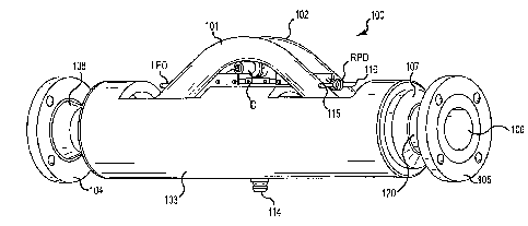
FIG. 1 shows a flow meter 100 according to an embodiment of the invention.
According to one embodiment of the invention, the flow meter 100 comprises a
Coriolis
flow meter. However, the present invention is not limited to applications
incorporating
Coriolis flow meters, and it should be understood that the present invention
could be used
with other types of flow meters. The flow meter 100 comprises a spacer 103
enclosing the
lower portion of the flow tubes 101, 102 which are internally connected on
their left ends to
flange 104 via its neck 108 and which are connected on their right ends via
neck 120 to
flange 105, and manifold 107. Also shown in FIG. 1 are the outlet 106 of
flange 105, left
pick-off LPO, right pick-off RPO, and driver D. The right pick-off RPO is
shown in some
detail and includes magnet structure 115 and coil structure 116. Element 114
on the bottom
of manifold spacer 103 is an opening for receiving from meter electronics (not
shown) a
wire (not shown) that extends internally to driver D and pick-offs LPO and
RPO. Flow
meter 100 is adapted when in use to be connected via flanges 104 and 105 to a
pipeline or
the like.
FIG. 2 shows a cut away view of the flow meter 100. This view removes the
front
portion of manifold spacer 103 so that parts internal to the manifold spacer
may be shown.
The parts that are shown on FIG. 2, but not on FIG. 1, include outer end brace
bars 201 and
204, inner brace bars 202 and 203, right end flow tube outlet openings 205 and
212, flow
tubes 101 and 102, curved flow tube sections 214, 215, 216, and 217. In use,
flow tubes 101
and 102 vibrate about their bending axes W and W'. The outer end brace bars
201 and 204
and the inner brace bars 202 and 203 help determine the location of bending
axes W and W'.
According to the embodiment shown in FIG. 2, the flow meter 100 includes a
pressure sensor 230. According to an embodiment of the invention, pressure
sensor 230
comprises a differential pressure sensor. Pressure sensor 230 is connected to
the flow meter
100 by means of pressure taps 231 and 232 to obtain a pressure reading. The
taps 231 and
6
CA 02895860 2015-06-29
232 allow pressure sensor 230 to continuously monitor the material pressure
drop across
flow meter 100. It should be noted that although the taps 231, 232 may be
connected to the
flow meter 100 at any desired location, according to the embodiment shown in
FIG. 2, the
taps 231, 232 are connected at the flanges 104, 105 respectively.
Advantageously, pressure
sensor 230 may obtain a differential pressure measurement for the entire flow
meter 100 and
not just the active portion of the flow meter 100. In other embodiments, such
as shown in
FIG. 4 below, the pressure taps 231, 232 may be located in the pipeline to
which the flow
meter is cormected. The differential pressure measurement is described further
below.
FIG. 2 also shows a plurality of temperature sensing devices 240. According to
the
embodiment shown in FIG. 2, the temperature sensing devices comprise RTD
sensors.
However, it should be understood that other temperature measuring devices may
be
implemented and the present invention should not be limited to RTD sensors.
Similarly,
although six RTD sensors 240 are shown, it should be understood that any
number of RTD
sensors may be implemented and still fall within the scope of the present
invention.
Both the pressure sensor 230 and the RTD sensors 240 are shown connected to
meter
electronics 20 via leads AP signal and RTD signal, respectively. As described
in FIG. 1, the
left and right pick-off sensors, LPO, RPO, as well as driver D, which are
shown in FIG. 1,
are also connected to meter electronics 20. Meter electronics 20 provides mass
flow rate
and totalized mass flow information. In addition, mass flow rate information,
density,
temperature, pressure, and other flow characteristics can be sent to
downstream process
control and/or measurement equipment via lead 26. Meter electronics 20 may
also comprise
a user interface that allows a user to input information such as fluid
viscosity along with
other known values. According to an embodiment of the invention, meter
electronics 20
comprises a hard drive capable of storing known information or calculated
information for
future retrieval. This stored information is discussed further below.
FIG. 3 shows a cross section view of a portion of the flow tube 101 with a
coating
310. Although only a portion of flow tube 101 is shown, it should be
appreciated that
coating 310 may also form inside flow tube 102 as well as other parts of the
flow meter 100
exposed to a process fluid. As the process fluid flows through the flow tube
101, deposits of
the process fluid may be left behind. Over time, these deposits form a coating
310. The
7
CA 02895860 2015-06-29
coating 310 may cover substantially the entire inside diameter of the flow
tube 101 as
shown, or alternatively, the coating 310 may be formed in certain areas of the
flow tube 101,
while other areas are free from coating 310. Furthermore, although, the
coating 310 in a
particular application may not be as thick as shown in FIG. 3, in some
processes the coating
310 becomes thick enough to substantially plug the flow meter 100. Even if the
coating 310
is not thick enough to plug the flow meter 100, it can reduce the cross
sectional area
provided for the process fluid to flow through. For example, the flow tube 101
may have an
internal diameter of Di; however, with the coating 310 present, the actual
allowable
diameter in which the process fluid can flow through is reduced to D2.
Because the coating 310 might adversely affect the performance of the flow
meter
100, the present invention provides alternative methods for determining the
presence of
coating 310 within the flow meter 100. Furthermore, while prior art methods
are limited to
detecting coating 310 only in the active part, i.e., the vibrating section of
the flow tubes 101,
102, the present invention is capable of detecting coating 310 in all sections
of the flow
meter 100, including the manifolds 104, 105. It should be understood however,
that the
present invention is not limited to the detection of coating, but rather the
present invention
provides alternative methods for detecting a deviation in a flow meter
parameter. The flow
meter parameter may be any measurement that is obtained from the flow meter.
In some
embodiments the deviation in the flow meter parameter is caused by coating
310. However,
other things may cause the deviation in the flow meter measurement as well,
such as
plugging of the meter, inconsistent temperatures, inconsistent process fluid
mixtures,
bubbles that form in the flow meter, etc. Therefore, according to an
embodiment of the
invention, the methods provided below detect a deviation in a flow meter
parameter, which
may provide a diagnostic that further investigation is required.
A deviation in a flow meter parameter may be detected according to one of the
methods described below. According to an embodiment of the invention, a
deviation in a
flow meter parameter is detected directly from the differential pressure
measurement
obtained from pressure sensor 230. At the factory, or alternatively, on site
when it is known
there is no coating 310 in the flow meter 100, for example, a plot of
differential pressure
across a portion of the flow meter 100 versus mass flow rate can be prepared
for a known
8
CA 02895860 2015-06-29
fixed fluid viscosity. Based on this plot, an expected differential pressure
can be determined
for a given flow rate. The actual differential pressure can then be
continuously monitored
using the pressure sensor 230 and compared to the expected differential
pressure for the
measured flow rate. If the actual differential pressure is within a threshold
limit of the
expected differential pressure, meter electronics 20 can send a signal that no
deviation in the
parameter is detected, or alternatively, little deviation has been detected in
the flow meter
parameter. If on the other hand, the measured differential pressure falls
outside of the
threshold limit, meter electronics 20 can flag the measurement for further
investigation.
According to one embodiment of the invention, the threshold limit comprises a
predetermined value. According to another embodiment of the invention, the
threshold limit
is set by a user or operator.
Although this approach provides satisfactory results, there are a number of
limitations using this direct comparison approach. First, the user must know
the viscosity of
the process fluid. Additionally, the viscosity must remain substantially
constant. This is
because the expected differential pressure obtained from the previous
measurements along
with the actual differential pressure is dependent on the viscosity of the
process fluid.
Because of this limitation, a change in the differential pressure may be
significant of a
condition other than coating, thereby giving a false coating indication.
Another method for detecting a deviation in a flow meter parameter is to
characterize
the flow meter 100 as an orifice meter. Orifice meters are generally known and
are used to
measure a fluid flow based on a differential pressure. They have certain
advantages over
other meters that measure fluid flow based on a differential pressure because
they occupy
much less space. An orifice meter operates by providing a plate with a hole in
a pipe, where
the hole is smaller than the diameter of the pipe. This reduction in the cross
sectional area
provided for fluid flow increases the velocity head at the expense of the
pressure head. This
differential pressure can be measured by pressure taps before and after the
plate. Using the
measured differential pressure, a fluid velocity can be calculated based on an
equation such
as, for example:
= Cõ 112AP
(1)
p 4 P
9
CA 02895860 2016-02-01
Where:
Võ = velocity through the orifice
13= ratio of orifice diameter to pipe diameter
AP ¨ differential across the orifice
p = fluid density
= orifice coefficient
It should be understood that other equations are known to calculate a fluid
flow rate
using an orifice meter and equation (1) is merely an example, which should not
limit the
scope of the invention. Generally, all of the unknowns can be measured or are
known,
except for the orifice coefficient, CO, which is typically determined
experimentally and
. varies from meter to meter. It is typically dependent on both 13 and the
Reynolds number,
which is a dimensionless number and is defined as:
p
Re ='=' (2)
Where:
D = diameter
V = average liquid velocity
= fluid viscosity
p = fluid density
= kinematic fluid viscosity
For many orifice meters, the orifice coefficient, Co, remains almost constant
and is
independent for Reynold's numbers greater than approximately 30,000. Like an
orifice
meter, the flow meter 100 experiences a measurable drop in pressure and can be
viewed as
an orifice meter as shown in FIG. 4.
FIG. 4 shows the flow meter 100 positioned within a pipeline 401 and connected
to
meter electronics 20. In FIG. 4, the internal structure of the flow meter 100
is not shown,
but rather, the flow meter 100 is shown as a simple block diagram. During
experimental
testing, the flow meter 100 can be characterized as an orifice meter. In other
words, the
pressure sensor 430 can measure the differential pressure between the inlet
410 of the flow
meter 100 and the outlet 411 using the pressure taps 431, 432, respectively.
With the
CA 02895860 2015-06-29
variables of equation (1) either known or easily obtainable by measurement and
the flow
meter 100 determining a flow rate, a flow meter coefficient can be determined
experimentally. The flow meter coefficient being similar to an orifice
coefficient. Once the
flow meter coefficient is known, a flow rate can be calculated based on the
differential
pressure across the flow meter 100 based on the same principals as a flow rate
is determined
using an orifice meter.
During normal operation, the flow rate measured by the flow meter 100 can be
compared to an expected flow rate obtained by a calculation using equation (1)
or a similar
equation used for calculating flow rates based on an orifice meter. If the
expected flow rate
falls outside of a threshold difference from the flow rate obtained from the
flow meter 100,
meter electronics 20 may signal a deviation in the flow meter parameter. The
deviation may
be caused by the presence of coating 310 within the flow meter 100. However,
the deviation
may be caused by something other than coating 310. If on the other hand, the
expected flow
rate obtained by characterizing the flow meter as an orifice falls within a
threshold
difference of the measured flow rate obtained by flow meter 100, meter
electronics 20 may
signal little or no deviation in the flow meter parameter. It should be
understood that the
dneshold difference may be predetermined or may be determined by an operator
based on
the particular circumstances.
Another method for detecting the presence of a deviation in a flow meter
parameter,
which provides higher accuracy and broader applicability than the previously
mentioned
approaches, is to use a friction factor, such as the fanning friction factor,
f Other friction
factors are generally known in the art such as the Darcy Weissbach friction
factor, which is
approximately 4f It should be understood that the particular friction factor
used is not
important for the purposes of the present invention as any applicable
equations can be
adjusted according to the friction factor used.
It is generally known in the art that pressure drop through pipes can be
quantified
and adjusted by using a friction factor f First, it is important to understand
how to
characterize a process fluid flowing through a circular pipe. For the purpose
of this
embodiment, the flow meter 100 can be characterized as a circular pipe having
a known
inner diameter and length. One important number in characterizing fluid flow
through a
11
CA 02895860 2015-06-29
pipe is the use of the Reynold's number, Re, described above in equation (2).
It should be
noted that the tube diameter, D, can be easily determined and is generally
known at the
factory. Many flow meters, including Coriolis flow meters are capable of
measuring fluid
aspects, such as the fluid density and the mass flow rate. From these two
quantities, the
average liquid velocity can be calculated. The fluid viscosity can also be
determined based
on a known, a calculated, or a measured value.
The friction factor of a system is defined as the ratio of the wall shear
stress to the
product of the density and the velocity head (I/2/2). It is often useful for
incompressible
fluid flow systems to characterize the friction factor, fin terms of the
Reynold's number, Re.
The exact equation varies depending on the particular characteristics of both
the fluid as
well as the pipe through which the fluid is flowing. It should be understood
that the
equations that follow are merely examples and other similar equations are
generally known
in the art. Therefore, the equations outlined below should not limit the scope
of the
invention. For laminar flow through a smooth pipe, the friction factor, f can
be
characterized as:
, 16
¨ (3)
Re
In contrast, for turbulent flow through a smooth pipe, the friction factor, f
can be
characterized as:
1
¨ 2.51n(RVf /8)+1.75 _____________________________________________ (4)
12
Equation (4) can be used with reasonable accuracy for 104<Re<106. Other
equations
are also known for correlating the friction factor to the Reynold's number
such as:
f = .046 Re-2 (5)
12
CA 02895860 2015-06-29
f =.0014.125
+ __________________________________________________________________ (6)
Re 32
Equation (5) is generally applicable for 50,000<Re<106 and equation (6) is
generally
applicable for 3,00O<Re<3x10⁶. Based on equation 1 and any of equations 3-6,
the friction
factor of the system can be determined with the only unknown being the
viscosity.
Depending on the flow rate, changes in the viscosity may be insignificant.
Alternatively, the
user could enter a nominal viscosity.
It is also generally known in the art that the friction factor f can be
characterized in
terms of the pressure drop AP through a system as follows:
DAP
f= (7)
2¨V2pL
Where:
AP = Differential pressure
L = length of tube between pressure taps
f= friction factor
V = average fluid velocity
p = fluid density
D = tube diameter
The differential pressure can be obtained by pressure sensor 230; the length
of the
flow meter 100 between the pressure taps 231, 232 can be easily measured; the
tube
diameter can also be easily measured; the fluid density can be obtained from
the flow meter
100, and the average velocity can be obtained based on the mass flow rate and
the density
measured from the flow meter 100. Therefore, all of the variables on the right
hand side of
equation (7) can be found.
According to an embodiment of the invention, a diagnostic is generated based
on the
presence of a deviation in a flow meter parameter by comparing a calculated
friction factor,
fe based on a differential pressure to an expected friction factor J. The
expected friction
factor fe can be obtained in a number of different ways. According to one
embodiment of
the invention, an expected friction factor fe can be determined either at the
factor or on site,
13
CA 02895860 2015-06-29
when it is known that there is little or no coating present. The expected
friction factor fe can
be obtained based on various flow rate measurements and therefore a curve of
friction factor
v. flow rate can be prepared. The expected friction factor, fe can be prepared
in advance and
stored in meter electronics 20. According to another embodiment of the
invention, the
expected friction factor fe can be calculated based on a correlation to the
Reynold's number
obtained during normal operation.
During normal operation according to an embodiment of the invention, the
pressure
sensor 230 can obtain a differential pressure measurement of the flow meter
100.
Additionally, the flow meter 100 can obtain a flow rate measurement. From the
flow rate
measurement along with the differential pressure measurement, a calculated
friction factor fe
can be calculated from equation (7). This calculated friction factor fe can be
compared to the
expected friction factor j. Variations in the two friction factors are
indicative of a deviation
in the flow meter parameter. According to one embodiment, the deviation may be
caused by
coating 310 in the flow meter 100. However, in other embodiments, the
deviation may be
caused by other situations, such as plugging, inconsistent process fluid
mixture, bubbles in
the process fluid, etc. If the calculated friction factor fe falls within a
threshold limit of the
expected friction factor fe, meter electronics 20 can determine that either no
or little
deviation is present in the flow meter parameter. If on the other hand, the
calculated friction
factor fe falls beyond the threshold limit of the expected friction factor f,
meter electronics
20 can send an alert that a deviation may be present within the flow meter
parameter.
According to one embodiment of the invention, the threshold limit may be
predetermined
based on the particular flow meter or flow characteristics. According to
another
embodiment of the invention, the threshold limit may be determined on site by
the user or
operator.
in addition to providing an accurate prediction of coating 230, among other
things,
this method may also determine a deviation in the flow meter parameter in the
absence of an
exactly known fluid viscosity. Depending on the flow rate of the fluid, a
small change in
viscosity may not result in a substantial change in the Reynold's number.
Therefore, an
average viscosity may be input by the user, without a further need to measure
the viscosity.
14
CA 02895860 2015-06-29
According to another embodiment of the invention, a deviation in a flow meter
parameter may be detected using temperature measurements. As the process fluid
flows
through the flow meter 100, the inlet temperature and the outlet temperature
remain
relatively close together. Similarly, the flow tube 101 and flow tube 102
remain at
substantially the same temperature. According to an embodiment of the
invention, the flow
meter 100 includes two or more temperature sensors, such as RTDs 240. Although
FIG. 2
only shows six RTDs, it should be understood that in other embodiments, the
flow meter
100 may include more or less than six RTD sensors 240. The RTD sensors 240 can
monitor
the temperature of the flow tubes 101, 102. Coating 310, for example, may
interfere with
the fluid flow through the flow tubes 101, 102. Therefore, the coating 310 may
also cause
unusual variations in the temperature gradient from the inlet to the outlet of
a given flow
tube, either 101 or 102. Additionally, coating 310 may cause a temperature
gradient from
flow tube 101 to flow tube 102. Plugging may also affect the temperature
gradient because
little or no fluid is actually traveling through the flow meter 100.
Therefore, according to an embodiment of the invention, a deviation in a flow
meter
parameter may be detected based on a temperature gradient. More specifically,
according to
an embodiment of the invention, a deviation may be determined by tracking a
change in the
temperature gradient obtained from more than one temperature sensor, such as
RTD sensor
240. According to one embodiment, the temperature gradient is measured from an
inlet of
the flow meter 100 to an outlet of the flow meter 100. According to another
embodiment of
the invention, the temperature gradient is measured from one flow tube 101 of
the flow
meter 100 to another flow tube 102 of the flow meter 100. According to an
embodiment of
the invention, coating 310 may be detected if a temperature gradient exceeds a
temperature
gradient threshold value. According to one embodiment, the temperature
gradient threshold
value comprises a predetermined value. According to another embodiment, the
temperature
gradient threshold is determined by a user or operator.
In some embodiments, the flow meter 100 may include a temperature gradient
even
in the absence of a deviation. Therefore, according to an embodiment of the
invention, a
deviation may be detected based on a change in the already existing
temperature gradient.
CA 02895860 2015-06-29
The description above provides multiple methods for detecting a deviation in a
flow
meter parameter of a flow meter 100. According to an embodiment of the
invention, the
deviation in the flow meter parameter may be used to generate a diagnostic,
which may be
indicative of coating. Each of the methods includes different advantages and
the particular
method employed may depend on the existing circumstances or equipment
available. Some
of the methods allow for a detection of a deviation in a parameter in the
absence of a
deviation in the flow rate measurement. In addition, more than one method or
all of the
methods discussed above may be incorporated into a single flow meter system.
Therefore,
meter electronics 20 may compare the detection of a deviation obtained using
one method to
the results obtained from another method.
The detailed descriptions of the above embodiments are not exhaustive
descriptions
of all embodiments contemplated by the inventors to be within the scope of the
invention.
Indeed, persons skilled in the art will recognize that certain elements of the
above-described
embodiments may variously be combined or eliminated to create further
embodiments, and
such further embodiments fall within the scope and teachings of the invention.
It will also
be apparent to those of ordinary skill in the art that the above-described
embodiments may
be combined in whole or in part to create additional embodiments within the
scope and
te;,-bg,s of the invention.
Thus, although specific embodiments of, and examples for, the invention are
described herein for illustrative purposes, various equivalent modifications
are possible
within the scope of the invention, as those skilled in the relevant art will
recognize. The
teachings provided herein can be applied to the' flow meters, and not just to
the
embodiments described above and shown in the accompanying figures.
Accordingly, the
scope of the invention should be determined from the following claims.
16