Note: Descriptions are shown in the official language in which they were submitted.
CA 02897354 2016-05-05
A HOLLOW FIBER MODULE HAVING THIN FILM COMPOSITE-
AQUAPORIN MODIFIED MEMBRANES
FIELD OF THE INVENTION
The present invention relates to a hollow fiber (HF) module having thin film
composite
(TFC) modified fiber membranes, such as having a polyamide TFC layer on the
outside
or inside of the fibers, or on both sides, and comprising aquaporin water
channels in said
TFC layer. The present invention also relates to a hollow fiber membrane
having a thin
film composite (TFC) modified separation layer comprising aquaporin water
channels,
such as having a polyamide TFC layer on the outside or inside of the fibers
and to a
method of preparing said TFC modification directly on the fibers as mounted in
the
module and where said TFC layer comprises aquaporin water channels immobilised
or
embedded in said layer.
BACKGROUND OF THE INVENTION
Recently, it has been shown how thin film composite hollow fiber membranes can
be
prepared for forward osmosis (Sukitpaneenit & Chung 2012) through interfacial
polymerization creating a polyamide thin layer on the inner surface of PES
hollow fiber
support membranes where a 2 wt % of meta-phenylene diamine (MPD) aqueous
solution
containing 0.5 wt % of triethylamine and 0.1 wt % of sodium dodecyl sulfate is
introduced through pumping from a bottom inlet into a vertically positioned HF
module
followed by air drying and then introduction of a 0.15 wt % of trimesoyl
chloride (TMC)
in hexane solution to form the polyamide thin film and finally purging with
air and curing
at 65 C, rinsing with deionized water and storing in deionized water.
Furthermore,
Peinemann et al. describes a method of preparing a similar TFC layer on the
interior
surface of a hollow fiber, cf. US published patent application No.
2007/0199892.
Moreover, Zhong et al. (2013) describe the development of TFC forward osmosis
hollow
fiber membranes using direct sulfonated polyphenylenesulfone as membrane
substrate.
However, for a wide range of separation applications where hollow fiber
modules are
employed it is of importance to be able to separate or filter out organic
solutes of
relatively low molecular weight during the filtration process. For example, in
haemodialysis where HF modules are widely used, a uremic toxin and organic
degradation product, such as indoxyl sulfate (Indoxyl sulfate potassium salt,
CAS
Number 2642-37-7, molecular weight 251.30) poses a particularly difficult
problem.
Indoxyl sulfate is accumulated in the serum of chronic kidney disease
patients. A part of
1
CA 02897354 2016-05-05
,
the dietary protein-derived tryptophan is metabolized into indole by
tryptophanase in
intestinal bacteria. Indole is absorbed into the blood from the intestine, and
is
metabolized to indoxyl sulfate in the liver. Indoxyl sulfate is normally
excreted into
urine. In haemodialysis patients, however, an inadequate renal clearance of
indoxyl
sulfate leads to its elevated serum levels, cf. Niwa T. (2010). Niwa et al.
(1997) have
advanced the hypothesis that accumulation of indoxyl sulfate accelerates
glomerular
sclerosis and progression of kidney disease. Administration of an oral
adsorbent lowers
indoxyl sulfate levels in undialyzed uraemic patients, cf Niwa et al. (1997).
Current
dialysis methods, i.e. haemodialysis and peritoneal dialysis, the latter being
characterised
by continuous ultrafiltration and solute removal, do not sufficiently remove
some low
molecular weight degradation products from serum, such as indoxyl sulfate and
p-cresol
(4-methylphenol, CAS No. 106-44-5, molecular weight 108.13). In addition,
small water-
soluble molecules, such as urea, uric acid and creatinine, and
peptides/proteins, such as
f32-microglobulin should preferably be removed during dialysis. A direct
association
between p-cresol, mainly reflecting p-cresyl sulfate, and overall mortality
and
cardiovascular disease in end-stage renal disease and in chronic kidney
disease has been
found. Likewise, direct associations between indoxyl sulfate and overall
mortality and
cardiovascular disease has been reported. In continuous hemofiltration therapy
loss of
physiological (vital) proteins should be minimized and removal of low (< 500
Da) and
middle molecular weight (from about 500 to about 40 kDa) uremic toxins and
peptides
should be optimized, cf. Wenhao Xie (2011).
Aoike (2011) mentions the most important features or quality parameters for
high
performance membranes for use in hemopurification therapies, i.e., high water
permeability, capability to remove a wide range of uremic toxins and other
characteristic
features. However, Aoike also points out that large pore size of existing high
performance membranes (HPM) will likely allow blood to be contaminated by the
dialysis fluid, because HPMs, such as polyacrylonitrile (PAN) membranes,
having a large
pore size allow untoward rapid diffusion of dialyzed endotoxin fragments back
into the
blood compartment.
Accordingly, it remains a problem in the art in providing hollow fiber modules
that are
able to separate low molecular weight compounds, enabling their removal from
liquids in
2
CA 02897354 2016-05-05
processes such as haemodialysis and in which the hollow fibre module combine a
high
water permeability with smaller pore sizes.
SUMMARY OF THE INVENTION
Broadly, the present invention provides a hollow fiber module which is able to
separate
low molecular weight compounds, for example enabling the HF module to
concentrate
organic compounds, including urea, indoxyl sulfate, p-cresol and/or p-cresyl
sulfate and
preferably compounds having a molecular weight of less than about 500 Da and
thus
enable improved removal of said compounds, e.g. from a liquid. Alternatively
or
additionally, the present invention aims to provide a hollow fiber module
having high
water permeability but with smaller pore sizes, such as having a pore diameter
of less
than about 5 to 10 nm, cf. Clark & Gao (2002).
Accordingly, in one aspect, the present invention provides a hollow fiber (HF)
module
having a TFC layer comprising aquaporin water channels formed on its fiber
surfaces,
such as the inner fiber surface (lumen).
In a further aspect, the present invention provides a method of preparing a
hollow fiber
module comprising HF membranes modified with a thin film composite (TFC) layer
comprising aquaporin water channels, said method comprising the steps of:
a) obtaining an aquaporin vesicles suspension (proteoliposomes or
proteopolymersomes) having from about 25 to about 500 LPR/POPR of protein,
b) preparing an aqueous solution of a di- or triamine,
c) dissolving a di- or triacyl halide in an apolar organic solvent,
d) preparing a mixture of amine and aquaporin vesicle by dissolving/mixing the
vesicles preparation from step a) with the solution from step b),
e) pumping the mixture from step d) through the lumen of the hollow fibers in
a
hollow fiber module using its end inlet,
0 removing excess aqueous solution by a gas purging of the lumen side of the
fibers using a module inlet,
g) injecting the acyl halide solution from step c) into the module through the
lumen of the hollow fibers to allow an interfacial polymerization reaction to
take place,
and
h) rinsing the module with an aqueous solvent by injection through a module
inlet.
3
CA 02897354 2016-05-05
In a further aspect, the present invention provides a method of preparing a
hollow fiber
module comprising HF membranes modified with a thin film composite (TFC) layer
comprising aquaporin water channels, said method comprising the steps of
a) obtaining an aquaporin vesicles suspension (proteoliposomes or
proteopolymersomes) having from about 25 to about 500 LPR/POPR of protein,
b) preparing an aqueous solution of 1,3-diaminobenzene of about 1% to about 5
%
(w/w) concentration,
c) dissolving benzene-1,3,5-tricarbonyl chloride in an organic solvent
selected
from the group consisting of hexane, heptane, octane or a mixture of solvents
to obtain a
.. concentration of about 0.05% to about 1% (w/v),
d) preparing an 1,3-diaminobenzene/aquaporin vesicle mixture by
dissolving/mixing the vesicles preparation from step a) with the solution from
step b),
e) pumping the mixture from step d) through the lumen of the hollow fibers in
a
hollow fiber module using its end inlet,
f) removing excess aqueous solution by a gas purging of the lumen side of the
fibers using a module inlet,
g) injecting the benzene-1,3,5-tricarbonyl chloride solution from step c) into
the
module through the lumen of the hollow fibers to allow an interfacial
polymerization
reaction to take place, and
h) rinsing the module with an aqueous solvent by injection through a module
inlet.
In a further aspect, the present invention provides a method of outside
coating a hollow
fiber membrane with a thin film composite (TFC) layer comprising aquaporin
water
channels, said method comprising the steps of:
a) obtaining an aquaporin vesicles suspension (proteoliposomes or
proteopolymersomes),
b) preparing an aqueous solution of a di- or triamine,
c) dissolving a di- or triacyl halide in an apolar organic solvent,
d) preparing a mixture of amine and aquaporin vesicle by dissolving/mixing the
vesicles preparation from step a) with the solution from step b),
e) passing the hollow fiber membrane through the mixture from step d),
f) removing excess aqueous solution,
g) passing the hollow fiber membrane through the acyl halide solution from
step c)
to allow an interfacial polymerization reaction to take place, and
4
CA 02897354 2016-05-05
h) rinsing the hollow fiber membrane with an aqueous solvent, e.g. by passing
the
hollow fibre through a water bath.
Moreover, the invention relates to a hollow fiber membrane modified with a
thin film
composite (TFC) layer comprising aquaporin water channels.
In a further aspect, the present invention provides the use of into a hollow
fiber (HF)
module as described herein for extraction of pure water through forward
osmosis or for
re-extraction of pure water from a patient's plasma lost through hemodialysis
In a further aspect, the present invention provides a method of extracting
water from an
aqueous liquid comprising the following steps:
a) placing a hollow fiber (HF) module of any one of claims 1 to 9 which is in
controlled connection with a first aqueous liquid (feed solution) having an
osmotic
pressure which is lower than or equal to that of the liquid membrane matrix,
and which is
further in controlled connection with a second aqueous liquid (draw solution)
having an
osmotic pressure which is higher than that of the matrix to create an osmotic
pressure
potential between said first and said second liquid,
b) allowing the matrix to absorb pure water from said first liquid and to
mediate a
pure water flux into said second liquid as long as an osmotic pressure
gradient exists,
c) optionally separating the extracted pure water from said second liquid.
Embodiments of the present invention will now be described by way of example
and not
limitation with reference to the accompanying figures. However various further
aspects
and embodiments of the present invention will be apparent to those skilled in
the art in
view of the present disclosure.
"and/or" where used herein is to be taken as specific disclosure of each of
the two
specified features or components with or without the other. For example "A
and/or B" is
to be taken as specific disclosure of each of (i) A, (ii) B and (iii) A and B,
just as if each is
set out individually herein.
Unless context dictates otherwise, the descriptions and definitions of the
features set out
above are not limited to any particular aspect or embodiment of the invention
and apply
5
CA 02897354 2016-05-05
equally to all aspects and embodiments which are described.
BRIEF DESCRIPTION OF THE DRAWINGS
Fig. lA shows as a photograph and a drawing a HF module having 9 hollow
fibers, two
end inlets/outlets (1, 2) and two side inlets/outlets (3, 4) as well as four
end caps (5) to
seal said inlets/outlets. Total length of the module: 100mm; diameter at
fibers: 10 mm;
diameter at sealing: 130mm.
Fig. 1B shows as a photograph and a drawing a HF module having 984 fibers, two
end
inlets/outlets (1, 2) and two side inlets/outlets (3, 4). Total length: 25cm,
fiber diameter of
700 Am.
Fig. 2 shows as a photograph and a drawing a cross section of part of a hollow
fiber,
UltraPESTM, having a wall thickness of about 220 gm 15 gm, an inner diameter
of
about 760 inn 30 pm, a molecular weight cut-off (MWCO, dextran, 90%, 0 bar)
of 65
kD 20 kD, and a transmembrane water flow of>0.65 m1/[min x cm2 x bar] at 25
C.
Picture obtained from MembranaTM GmbH.
Fig. 3 shows a principle sketch of the microstructure of the thin film
composite layer
formed on a hollow fiber of the invention, cf. Example 1 below.
Fig. 4 shows a principle sketch of a process for automatized continuous
outside coating of
hollow fibers.
DETAILED DESCRIPTION
More specifically, the present invention relates to a HF module having
polyethersulfone
(PES) fibers or fibers of other suitable porous support material, such as
polysulfone,
polyphenylene sulfone, polyether imide, polyvinylpyrrolidone and
polyacrylonitrile
including blends and mixtures thereof, which has been modified by forming a
thin film
composite layer, e.g. through interfacial polymerization. In addition, various
doping
materials may be used when manufacturing the hollow fiber support materials,
cf. e.g.
Qian Yang et al. (2009). Such HF modules are commonly used in food and
beverage
applications such as filtering beer and wine, but also in some water and
wastewater
applications including wastewater reuse and pool water recycling. For
instance, the
6
CA 02897354 2016-05-05
= German company MembranaTM supplies a hollow fiber module containing
several
thousands of fibers with an overall surface area of 75 square meters per
module. Smaller
modules with typically 1 -2 square meters and around 8,000 to 20,000 fibers
are
commonly used in medical dialysis applications (Fresenius Medical CareTM,
GambroTm).
.. In principle, all these commercial products can be coated through
interfacial
polymerization using the method of the invention resulting in a thin film
composite layer
wherein aquaporin water channels are incorporated, preferably during its
formation, such
as by adding a suitable protein suspension or solution, preferably in vesicle
form, to the
aqueous reactive amine solution, e.g. a meta-phenylene diamine solution, and
pumping or
injecting the combined solution through the support fibers, removing excess
solution and
subsequently pumping or injecting a reactive acyl chloride in organic solvent,
e.g.
trimesoyl chloride in hexane, and finally rinsing with deionized water, e.g.
MiIliQTM
water. The housing material of the HF modules of the invention can be any
suitable
material commonly used for HF modules, such as polypropylene, polyethylene,
PVDF
and stainless steel. The fibers may be sealed into the HF module housing using
commonly
known epoxy adhesive materials and the like. Additional examples of HF modules
that
may be TFC modified according to the invention are found on websites of
membrane
producers.
25
In one embodiment of the present invention, the HF module is operated with
counter-
current flow of draw and feed solutions. In another embodiment of the present
invention
the HF module is operated with co-current flow of draw and feed solutions. In
a further
embodiment of the invention the HF module is operated with the draw solution
against
the TFC layer. In a still further embodiment of the invention the HF module is
operated
with the feed solution against the TFC layer. In addition, the modified hollow
fibres of
7
CA 02897354 2016-05-05
the invention may be mounted in a system or module for use as a membrane bio-
reactor
(MBR), where the MBR module containing the hollow fibres is submerged in an
aqueous
liquid and where purified water is removed from said liquid through the fibres
by the use
of a draw solution or by application of a moderate suction pressure.
A further aspect of the invention relates to a method of making a hollow fiber
membrane
modified with a thin film composite (TFC) layer comprising aquaporin water
channels,
where the TFC layer comprising aquaporin water channels is prepared directly
on the
surface of membrane fibers mounted and sealed in a HF module, said method
comprising
the steps of:
a) obtaining an aquaporin vesicles suspension (proteoliposomes or
proteopolymersomes) having from about 25 to about 500 LPR/POPR (ratio based on
mole content) (preferably 100 LPR/POPR for lipid/diblock copolymer, 50 POPR
for
triblock copolymer) of protein,
b) preparing an aqueous solution of a diamine, such as 1,3-diaminobenzene, to
obtain a solution of about 1% to about 5 %, such as about 2.5 to 4.2% (w/w)
concentration,
c) dissolving an acyl chloride, such as benzene-1,3,5-tricarbonyl chloride in
a
hydrocarbon solvent, such as hexane, heptane, octane, nonane having a straight
or
branched hydrocarbon chain to or mixtures of these, such as isoalkane
hydrocarbon
solvent obtain a concentration of about 0.05% to about 1 %, such as about
0.15% (w/v),
d) preparing a diamine /aquaporin vesicle mixture, such as1,3-
diaminobenzene/aquaporin vesicle mixture by dissolving/mixing the vesicles
preparation
from step a) with the solution from step b),
e) pumping the mixture from step d) through the lumen of the hollow fibers in
a
hollow fiber module using its end inlet,
f) removing excess diamine by a gas purging of the lumen side of the fibers
using
a module inlet,
g) injecting the acyl chloride solution from step c) into the module through
an inlet
to allow an interfacial polymerization reaction to take place, and
h) rinsing the module with an aqueous solvent by injection through a module
inlet.
Optionally, after filling with water the module is sealed with tight caps to
prevent it from
drying out.
8
CA 02897354 2016-05-05
A further aspect of the invention relates to a method of outside coating a
hollow fiber
membrane with a thin film composite (TFC) layer comprising aquaporin water
channels,
said method comprising the steps of:
a) obtaining an aquaporin vesicles suspension (proteoliposomes or
proteopolymersomes),
b) preparing an aqueous solution of a di- or triamine,
c) dissolving a di- or triacyl halide in an apolar organic solvent,
d) preparing a mixture of amine and aquaporin vesicle by dissolving/mixing the
vesicles preparation from step a) with the solution from step b),
e) passing the hollow fiber membrane through the mixture from step d),
f) removing excess aqueous solution,
g) passing the hollow fiber membrane through the acyl halide solution from
step c)
to allow an interfacial polymerization reaction to take place, and
h) rinsing the hollow fiber membrane with an aqueous solvent, e.g. by passing
the
hollow fibre through a water bath.
In the above described methods of coating the hollow fiber membrane and
preparing the
hollow fiber module, the steps a)-c) may be performed in any convenient order.
Also the
step c) may be performed before or after step d).
In exemplary embodiments, said liposomes used in the preparation of the HF
module of
the invention are prepared from lipids such as DPhPC, DOPC, mixed soy bean
lipids,
such as asolectin and soy lecithin, or E. coli mixed lipids; and said
polymersomes may
comprise triblock copolymers of the hydrophile-hydrophobe-hydrophile (A-B-A or
A-B-
C) type or diblock copolymers of the hydrophile-hydrophobe type (A-B).
In a further embodiment said polymersomes may comprise a combination of
triblock
copolymers of the hydrophile-hydrophobe-hydrophile type and diblock copolymers
of the
hydrophile-hydrophobe type. In the combinations the diblock copolymers may
comprise
from about 10 mole % to about 60 mole %, such as from about 25 mole % to about
50
mole %.
9
CA 02897354 2016-05-05
Said aquaporin water channels are preferably AqpZ channels, but, in principle,
all water
selective aquaporins, e.g. such as aquaporin Z (AqpZ), Aqpl, GlpF or SoPIP2;1,
are
useful in the invention.
Said TFC layer is preferably formed through interfacial polymerization of an
aqueous
solution of an amine with a solution of an acid chloride in an organic
solvent, and wherein
the aquaporin water channel vesicles are incorporated in said aqueous
solution.
Said aquaporin water channels are preferably incorporated in vesicles before
incorporation into the TFC layer of the hollow fiber membrane of the
invention, and said
vesicles may be in the form of liposomes or polymersomes, where said liposomes
are
prepared from lipids such as DPhPC, DOPC, mixed soy bean lipids, or E. coli
mixed
lipids, and said polymersomes comprise triblock copolymers of the hydrophile-
hydrophobe-hydrophile (A-B-A or A-B-C) type or diblock copolymers of the
hydrophile-
hydrophobe type (A-B). In a further embodiment said polymersomes may comprise
a
combination of triblock copolymers of the hydrophile-hydrophobe-hydrophile
type and
diblock copolymers of the hydrophile-hydrophobe type.
The HF membrane of the invention has preferably a TFC layer formed through
interfacial
polymerization of an aqueous solution of an amine with a solution of an acid
chloride in
an organic solvent, and wherein the aquaporin water channel vesicles are
incorporated in
said aqueous solution.
In one embodiment of the method of preparing the HF module of the invention
the fibers
are gas purged to blow off excess water in step f) and the module is held
upside down in
step f).
In a further aspect of the present invention, a hollow fiber module having
high water
permeability and small pore sizes, such as having a pore diameter of less than
about 5 to
10 nm, such as equal to or less than about 1 nm, is provided. Formation of a
separation
layer in the form of a thin film layer as known in the art onto the surface of
a support
membrane fiber results in changes to the water transport mechanism. Instead of
water
transport taking place by normal diffusion through the pores of the support
membrane,
another type of water transport takes place through the thin film layer as is
known from
this type of reverse osmosis membranes, where membrane permeability is
limited. The
CA 02897354 2016-05-05
nonporous nature of the thin film separating layer results in transport of
water requiring
"jump diffusion" as described in Kotelyanskii et al. 1998. Thus, thin film
modification of
water membranes have mainly found use in reverse osmosis, where a hydrostatic
pressure
is required to force the water through the membrane, and the obtained
advantage lies in
the improved separation of unwanted solutes in the water to be filtered. These
conventional membranes for reverse osmosis have effectively 100-200 nm thick
non-
porous layers supported by a porous material. Water permeation in these
membranes
occurs as a diffusion process through the non-porous layer established via the
appearance
and disappearance of interstitial spaces. The HF module of the present
invention may be
further improved relative to the prior art reverse osmosis membranes by having
aquaporin
water channels incorporated in the thin film layer making it a thin film
composite (TFC)
layer. The incorporation of aquaporins have the added benefit of providing a
selective
water transport through its pores having a diameter of only 2.4 A at its
narrowest passage
(AqpZ pore, cf. Wang et al. 2005) where an efficient single file water
transport takes
place. The HF module of the invention combines the advantages of having a thin
film
separation layer together with aquaporin water channels thus providing
improved
separation as well as water flux through Angstrom sized pores making the HF
module
suitable for both reverse osmosis, forward osmosis, assisted forward osmosis,
nanofiltration etc.
DEFINITIONS
The term "hollow fiber membrane" and "HF membrane" as used herein refers to
any type
of capillary membrane which can be used for liquid filtration purposes.
The term "polyethersulfone" as used herein refers to a membrane material used
in the
fabrication of hollow fiber modules. An example is the membrane material
UltraPESTM
marketed by MembranaTM GmbH. A cross section microscope photo of an UltraPesTM
fiber is shown in Fig. 2, cf. MembranaTM GMBH.
"Aquaporin" as used herein refers to selective water channel proteins,
including AqpZ
and SoPIP2;1 prepared according to the methods described by Maria Karlsson et
al.
(FEBS Letters 537 (2003) 68-72) or as described in Jensen et al. US
2012/0080377 Al.
11
CA 02897354 2016-05-05
"Asolectin" as used herein refers to a soybean lecithin fraction [IV-S}, which
is a highly
purified phospholipid product containing lecithin, cephalin, inositol
phosphatides &
soybean oil (synonym: azolectin).
"Block copolymer" as used herein refers to membrane forming or vesicle forming
di- and
tri-block copolymers having both hydrophilic (A or C) and hydrophobic (B)
blocks; the
diblock copolymers being of the A-B or C-B type which are able to form
bilayers and the
triblock copolymers being of the A-B-A or A-B-C type that form monolayers by
self
assembly, where all of the membranes have the hydrophobic layer in the middle.
Examples of useful diblock copolymers and examples of useful triblock
copolymers are
the following:
Species Supplier Formula n(hydrophobic) n(hydrophilic)
P7258 Polymer Source TM E0481DMS70 70 48
P5809 Polymer SourceTM E015B016 15 16
P8365 Polymer SourceTM E025DMS8 8 25
P7259 Polymer SourceTM E048DMS14 14 48
P7261 Polymer Source TM E01 14DM S ta 14 114
P369 1B Polymer SourceTM MOXA6DMS35MOXA6 35 12
P8061 Polymer SourceTM MOXAI5DMS67MOXA15 67 30
P9548 Polymer SourceTM MOXA15DMSII9MOXA15 119 30
where EO-block-DMS-block, such as E025DMS8, represents poly(dimethylsiloxane-
block-
ethylene oxide-block),
E0-block-B0-block, such as E018B018, represents poly(butylene oxide-block-
ethylene
oxide-block), and MOXA-block-DMS-block-MOXA-block, such as MOXA6DMS MOXA _ _35
_ .6,
represents poly(2-methyloxazoline-block-dimethylsiloxane-block-2-
methyloxazoline).
The diblock and triblock copolymers can be used as single components or as
mixtures in
the creation of biomimetic membranes, such as vesicles or planar membranes,
for
incorporation of the aquaporins having amphiphilic properties due to their
native
transmembrane properties and functions.
12
CA 02897354 2016-05-05
"Liquid membrane" as used herein refers to membrane systems as disclosed in
W02010/146365 (Aquaporin A/S) and WO 2012/080946 (Aquaporin A/S). Said liquid
membrane is an integral component of the TFC HF membranes of the invention
wherein
it is immobilized or encapsulated.
The term "assisted forward osmosis" (or "pressure assisted forward osmosis")
as used
herein refers to the concept of applying a mechanical pressure to the feed
side of the
membrane to enhance the water flux through synergising the osmotic and
hydraulic
driving forces.
"Thin-film-composite" or (TFC) Hollow Fiber Membranes as used herein are
prepared
using an amine reactant, preferably an aromatic amine, such as a diamine or
triamine,
e.g.1,3-diaminobenzene (m-Phenylenediamine > 99%,e. g. as purchased from Sigma-
AldrichTM) in an aqueous solution, and an acyl halide reactant, such as a di-
or triacid
chloride, preferably an aromatic acyl halide, e.g. benzene-1,3,5-tricarbonyl
chloride (CAS
No. 84270-84-8, trimesoyl chloride (TMC), 98%, e.g. as purchased from Sigma-
AldrichTM) dissolved in an organic solvent where said reactants combine in an
interfacial
polymerization reaction, cf. US 4,277,344 which describes in detail the
formation of a
composite membrane comprising a polyamide laminated to a porous membrane
support,
at the surface of the support membrane, e.g. a polyethersulfone membrane.
Benzene-
1,3,5-tricarbonyl chloride is dissolved in a solvent, such as a C6 ¨ C12
hydrocarbon
including hexane (>99.9%, Fisher ChemicalsTm), heptane, octane, nonane, decane
etc.
(straight chain or branched hydrocarbons) or other low aromatic hydrocarbon
solvent, e.g.
IsoparTM G Fluid which is produced from petroleum-based raw materials treated
with
hydrogen in the presence of a catalyst to produce a low odour fluid the major
components
of which include isoalkanes. IsoparTM G Fluid: Chemical Name: Hydrocarbons,
C10-C12,
isoalkanes, <2% aromatics; CAS No: 64742-48-9, chemical name: Naphtha
(petroleum),
hydrotreated heavy (from ExxonMobilTm Chemical). Alternatives to the reactant
1,3-
diaminobenzene include diamines such as hexamethylenediamine etc., and
alternatives to
the reactant benzene-1,3,5-tricarbonyl chloride include a diacyl chloride,
adipoyl chloride
etc. as known in the art.
"Gas" as used herein means any gaseous fluid, such as inert gases, dinitrogen,
atmospheric air, etc. that can be used for blowing off the solvent,
13
CA 02897354 2016-05-05
Proteoliposomes as used herein typically have a lipid to protein ratio (LPR
calculated on a
mole basis) of between 25 to 500, such as about 100 to about 200.
Proteopolymersomes as used herein typically have a polymer to protein ratio
(POPR
calculated on a mole basis) of between 25 to 500, such as about 50 to about
100 when
using a triblock copolymer and a polymer to protein ratio of between 25 to
500, such as
about 100 to about 200 when using a diblock copolymer.
In a preferred embodiment of the invention the hollow fiber bundles comprise a
polyethersulfone (U1traPESTM) support material in the form of a hydrophilic
capillary
membrane material having the following characteristics (mean values are
given):
Physical characteristics: Wall thickness 220 gm 15 gm; inner diameter 760gm
30
gm; tensile strength? 410 cN; elongation at break? 40 %; explosion pressure?
12 bar;
implosion pressure? 7 bar; Minimal pore size of 6 ¨ 7 nm.
Membrane performance characteristics: Transmembrane flow (water, 25 C)? 0.65
m1/[min x cm' x bar]; molecular weight cut off MWCO (dextran, 90%, 0 bar) 65
kD 20
ka
The characteristics given are representative of a preferred UltraPES material
provided by
MembranaTM GmbH, Oehder Stree 28, D ¨ 42289 Wuppertal, Germany.
In another preferred embodiment of the invention the hollow fibre bundles
comprise the
polyethersulfone MicroPES , such as the TF10 version also provided by
MembranaTM
GmbH, support material, which differs from the UltraPES material in having a
Transmembrane flow (water, 25 C)? 35 m1/[min x cm' x bar]; wall thickness of
100 gm
25 gm; an inner diameter of 300gm 40 gm; tensile strength of? 50 cN;
elongation at
break? 30 %; maximum pore size of 0.5gm 0.1 gm.
EXPERIMENTAL EXAMPLES
Preparation of lmg/mL Asolectin proteoliposomes, and lipid to protein ratio
(LPR)
200 using AqpZ Mw 27233 according to the following protocol:
14
CA 02897354 2016-05-05
1) Fill a 50 mL glass evaporation vial with 5 mL of a 2 mg/mL stock solution
of asolectin
(mW 786.11 g/mol, Sigma) in CHC13.
2) Evaporate the CHC13 using a rotation evaporator for at least 2h to complete
dryness.
3) Add 0.8 mL of buffer solution (1.3% octylglucoside (OG) in PBS pH 7.4) to
rehydrate
the film obtained in the evaporation vial in step 2.
4) Shake the vial at maximum rpm on a platform shaker (HeidolphTM orbital
platform
shaker Unimax 2O1OTM or equivalent) until the lipid is dissolved.
5) Add 1.73 mg of AqpZ in a protein buffer containing Tris pH8, glucose and
OG, 10
mg/mL, and rotate vial for 15 min at 200rpm, the AqpZ being prepared according
to
description herein.
6) Slowly add 9.03 ml PBS (pH 7.4 without OG), and shake vial for 15 min at
200rpm.
7) Freeze/thaw the combined solution/suspension on dry ice/40 C water bath
for three
times to eliminate possible multilamellar structures.
8) Add 250mg of hydrated BiobeadsTM (SM2 from BioRadTM) and rotate vial for lh
at
.. 200rpm at 4 C to adsorb detergent (OG).
9) Add further 250mg of hydrated BiobeadsTM and rotate vial for 2 to 3 days at
200rpm at
4 C.
10) The BiobeadsTM with adsorbed OG are then removed by pipetting off the
suspension.
11) Extrude the obtained suspension for about 11 times through a 200nm
polycarbonate
filter using an extruder (such as an EmulsiF1exC5TM from AvestinTM, Canada) at
least 1
time and up to about 22 times to obtain a uniform proteoliposome suspension
(vesicles)
suspension.
Protocol for 1mg/m1 proteo-polymersomes, protein to polymer ratio (POPR) 50
Polyoxazoline Based Triblock Copolymers, Poly(2-methyl oxazoline-b-dimethyl
siloxane-b-2-methyl oxazoline, Moxa 12: DMS 35, Mw 3510) (P3691 purchased from
Polymer SourceTM, Quebec, Canada), AqpZ Mw 27233
1) Fill a 50 ml glass evaporation vial with 5m1 of a 2 mg/ml stock solution of
P3691 in
CHC13.
2) Evaporate the CHC13 using a rotation evaporator for at least 2h to complete
dryness.
3) Add 3.0 mL of buffer solution (1.3% 0.G.; 200mM Sucrose; 10mM Tris pH 8;
50mM
NaC1) to rehydrate the film obtained in the evaporation vial in step 2.
4) Shake the vial at 200 rpm on a platform shaker (HeidolphTM orbital platform
shaker
Unimax 2O1OTM or equivalent) for 3 hours to obtain dissolution of the
copolymer.
CA 02897354 2016-05-05
5) Add 1.55mg 1_, of AqpZ in a protein buffer containing Tris, glucose and
OG, and
rotate vial over night at 200rpm and 4 C.
6) Add 6.88 ml buffer (10mM Tris pH 8; 50mM NaCl) slowly while mixing up and
down
with pipette.
7) Add 180mg hydrated BiobeadsTM and rotate for lh at 200rpm.
8) Add 210mg hydrated BiobeadsTM and rotate for lh at 200rpm.
9) Add 240mg hydrated BiobeadsTM and rotate O.N. at 200rpm 4 C.
10) Add 240mg hydrated BiobeadsTM and rotate O.N. at 200rpm 4 C.
11) The BiobeadsTM with adsorbed OG are then removed by pipetting off the
suspension.
12) Extrude the suspension for about 21 times through a 200nm polycarbonate
filter using
an extruder, such as from at least 1 time and up to about 22 times to obtain a
uniform
proteopolymersome suspension (vesicles) suspension.
Example 1. Preparation of a hollow fiber module wherein the inside surface of
the
fibres has been functionalised with immobilised AqpZ vesicles
Using a hollow fiber module having polyethersulfone membranes, such as a
custom-made
module, such as having 9 fibers corresponding to about 10 cm2 outside area and
5 cm2
inside area, or such as having a membrane area of up to 0.5 m2 which may
correspond to
several hundred fibers depending on module length (MembranaTm GmbH, Wuppertal,
Germany), the module being prepared essentially as described by Sukitpaneenit
et al.
2011, a thin film composite layer is prepared on the inside fiber surface
through
interfacial polymerization involving the following steps:
1) Obtaining 4 mL of AqpZ vesicles as prepared in the example above.
2) Dissolve 250 mg of 1,3-diaminobenzene in 6 mL of Mi11iQTM water to obtain a
solution of 4.2% (w/w) concentration.
3) 75 mg ofbenzene-1,3,5-tricarbonyl chloride is dissolved in 50 mL of hexane
to obtain
a final concentration of 0.15% (w/v)
4) A 1,3-diaminobenzene/AqpZ vesicle mixture is prepared by dissolving/mixing
4 mL of
the vesicles preparation from step 1 with 6 mL of the solution from step 2.
5) The mixture obtained in step 4 is constantly pumped through the module for
2 minutes
using end inlet 1 (or inlet 2), cf. Fig. 1.
6) Excess 1,3-diaminobenzene is removed by a constant air purging of the lumen
side of
the fibers for 2 minutes using, e.g., inlet 1, cf. Fig. 1, preferably holding
the module
upside down.
16
CA 02897354 2016-05-05
7) A constant flow of the benzene-1,3,5-tricarbonyl chloride solution from
step 3 is then
injected into the module through inlet 1 for approximately 30s using a syringe
pump,
e.g.from TSE systemsTM, cf. to allow the interfacial polymerization reaction
to take place.
8) Finally, the module is preferably rinsed with MilliQTM water, approximately
10 mL are
used, by injection through side inlet 3 and 4.
After filling it with water the module is sealed with the white sealing caps
(5), cf.
fig. 1, to prevent it from drying out (the sealing caps are part of the module
and it is
delivered with them).
Alternatively, steps 2 and 3 are as described below where all other steps are
the same as
shown above:
2) Dissolve 1,3-diaminobenzene in MilliQTM water to obtain a solution of 4.2%
(w/w)
concentration.
3) benzene-1,3,5-tricarbonyl chloride is dissolved in a solvent such as hexane
or isoalkane
hydrocarbon solvent to obtain a final concentration of 0.15% (w/v).
Example 2. Preparation of a hollow fiber module wherein the inside surface of
the
fibres has been functionalised with immobilised AqpZ vesicles
Using the same hollow fiber module as in Example 1 a thin film composite layer
is
prepared on the inside fiber surface through interfacial polymerization
involving the
following steps:
1) Obtaining 4 mL of AqpZ vesicles as prepared in the example above.
2) Dissolve 250 mg of 1,3-diaminobenzene in 6 mL of MilliQTM water to obtain a
solution of 4.2% (w/w) concentration.
3) 75 mg of benzene-1,3,5-tricarbonyl chloride is dissolved in 50 mL of hexane
to obtain
a final concentration of 0.15% (w/v)
4) A 1,3-diaminobenzene/AqpZ vesicle mixture is prepared by dissolving/mixing
4 mL of
the vesicles preparation from step 1 with 6 mL of the solution from step 2.
5) The mixture obtained in step 4 is constantly pumped through the module for
2 minutes
using end inlet 1 (or inlet 2), cf. Fig. 1.
6) Excess 1,3-diaminobenzene is removed from the module by a constant stream
of an
organic fluid such as hexane for lmin through inlet 1 using a syringe pump.
17
CA 02897354 2016-05-05
7) A constant flow of the benzene-1,3,5-tricarbonyl chloride solution from
step 3 is then
injected into the module through inlet 1 for approximately 30s using a syringe
pump,
e.g.from TSE systemsTM, cf. to allow the interfacial polymerization reaction
to take place.
8) Finally, the module is preferably rinsed with MilliQTM water, approximately
10 mL are
used, by injection through side inlet 1 and 3.
After filling it with water the module is sealed with the white sealing caps
(5), cf.
fig. 1, to prevent it from drying out (the sealing caps are part of the module
and it is
delivered with them).
Alternatively, steps 2 and 3 are as described below where all other steps are
the same as
shown above:
2) Dissolve 1,3-diaminobenzene in MilliQTM water to obtain a solution of 4.2%
(w/w)
concentration.
3) benzene-1,3,5-tricarbonyl chloride is dissolved in a solvent such as hexane
or isoalkane
hydrocarbon solvent to obtain a final concentration of 0.15% (w/v).
Example 3. Preparation of a hollow fiber module wherein the inside surface of
the
fibres has been functionalised with immobilised AqpZ vesicles
Using the same hollow fiber module as in Example 1 a thin film composite layer
is
.. prepared on the inside fiber surface through interfacial polymerization
involving the
following steps and using a syringe pump to push solutions through the module:
1) Obtaining 4 mL of AqpZ vesicles as prepared in the example above.
2) Dissolve 250 mg of 1,3-diaminobenzene in 6 mL of MilliQTM water to obtain a
solution of 4.2% (w/w) concentration.
3) 75 mg of benzene-1,3,5-tricarbonyl chloride is dissolved in 50 mL of hexane
to obtain
a final concentration of 0.15% (w/v).
4) A 1,3-diaminobenzene/AqpZ vesicle mixture is prepared by dissolving/mixing
4 mL of
the vesicles preparation from step 1 with 6 mL of the solution from step 2.
5) Add the solution from step 2 through the inside of the fibers while holding
the module
vertically with inlet down making sure that the air is let out); the solution
can preferably
be pumped using a flow rate of about 5 mL/min and continue pumping the
solution
through for 2 min, e. g. such as starting timing immediately after the
solution could be
seen in upper end of module.
18
CA 02897354 2016-05-05
6) Disconnect the module from the syringe pump and turn it around to have
excess
solution flow out into collection glass.
7) Connect the module upside down to air and slowly start air flow until 10
L/min is
reached; let air flow for 2 min.
8) Connect the module to a benzene-1,3,5-tricarbonyl chloride solution
syringe, hold the
module in vertical position and start benzene-1,3,5-tricarbonyl
chloride/hexane flow. e.g.
while keeping a flow rate of about 15 mL/min.
9) Disconnect module from hexane syringe and turn upside down to get last
hexane out;
connect to air and purge at about 10 L/min for 5-10 s.
10) Fill module with MilliQTM by sucking it in from a glass container.
Alternatively, steps 2 and 3 are as described below where all other steps are
the same as
shown above:
2) Dissolve 1,3-diaminobenzene in Mi1liQTM water to obtain a solution of 4.2%
(w/w)
concentration.
3) Benzene-1,3,5-tricarbonyl chloride is dissolved in a solvent such as hexane
or
isoalkane hydrocarbon solvent to obtain a final concentration of 0.15% (w/v).
Alternatively, in the pHF22 protocol we use a syringe pump to push solutions
through the
module, such as a MicroPES-TF10 HF module, then after obtaining 4 mL of AqpZ
vesicles as prepared in the example above, follow the steps below:
1) Dissolve MPD in MilliQTM water and add the AqpZ vesicles to get a 2.5%(W/W)
concentration of MPD in water/vesicle solution
2) Dissolve TMC in an organic solvent, such as hexane or an isoalkane
hydrocarbon
solvent, to a final concentration of 0,15% WN
.. 3) push MPD solution through the inside of the fibers while holding it
vertically with inlet
down (while filling the module repeatedly shake it to get the air out); 5
mL/min flow rate
4) continue pushing MPD solution through for 1 min (time starts after MPD
solution
could be seen in upper end of module) and then let it soak with MPD solution
inside for 1
min
5) disconnect module from syringe and turn it around to have excess MPD flow
out into
collection glass
6) connect the module upside down (meaning end with number on top) to air and
slowly
start air flow; dry with controlled air stream for 1 to 2 min and turn module
in between
19
CA 02897354 2016-05-05
7) connect to TMC solution, hold vertical (numbered end on bottom) and start
TMC
solution flow (flowrate: 10 mL/min)
8) let solution run through the fibers for 45 s (after the module is filled,
it can be tilted
back to horizontal position)
9) disconnect module from syringe and turn upside down to get last TMC
solution out;
connect to air and purge at 10 L/min for 5-10 s
10) fill module with MilliQTM by sucking it in from a glass
Following the various methods outlined above a TFC-aquaporin modified hollow
fiber
module is obtained where the inner surface of the fibers have acquired a novel
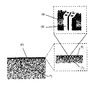
microstructure as shown in Fig. 3, where (6) refers to the TFC layer ¨200nm
and (7)
refers to the support membrane of 220 m, (6) and (7) together represents a
cross section
of the hollow fiber wall; (8) schematically represents the bilayer membrane in
the case of
lipids and diblock copolymers as amphiphilic membrane forming materials having
hydrophilic head groups and hydrophobic tail groups. Feature (8) would show a
monolayer having a hydrophobic middle portion and hydrophilic end portions or
would
show a type of bilayer where the triblock copolymers assume a horseshoe
conformation
or mixtures of both when triblock copolymers are used for the amphiphilic
membrane
material. (9) Represents the aquaporin protein where its tetrameric form is
shown.
However, the protein may also be present as a monomer or as a dimer, both of
which are
also water channels.
Filtration results using forward osmosis
Tables 1 and 2 below show filtration results in the form of measured water
flux, Jw, and
measured reverse salt flux, Js, for HF modules prepared according to the
invention using
a feed solution of 10 [tM calcein (CAS No. 1461-15-0, Mw 622.55) and a draw
solution
of 2 M NaCl both in deionized water (MilliQTm water) and where the TFC-
aquaporin
layer is formed on the inside of hollow fibers (lumen) and the draw solution
is applied to
the outside or inside of the fibers. Co-current or counter-current flow was
used. Referring
to Fig. 1: Typically, feed solution was pumped through inlet (1) and out
through (2), and
draw solution was pumped through inlet (3) and out through (4). In five
experiments a
counter-current flow was used, cf. Tables 1 and 2 and description below. The
water
channel protein AqpZ was used in all experiments, and both a lipid (asolectin)
and
various block copolymers (P3691, P8061) were vesicle membrane materials.
CA 02897354 2016-05-05
Each experiment is characterised by the water flux (Jw), the reverse salt flux
(Js) and the
calcein rejection. The water flux describes how much water is transported over
a certain
amount of membrane area in a given time (usually L/m2h) and is measured by
monitoring
the weight loss in the feed solution. The reverse salt flux characterises the
amount of draw
solute that diffuses back into the feed solution. It is an indicator on how
salt-tight a
membrane is. The Js is determined by measuring the conductivity changes in the
feed
solution. The calcein rejection is used to determine the forward rejection
properties of a
membrane. Here, a fluorescent marker, that is easily detectable by a desktop
fluorometer
(e.g. QubitTM fluorometer, InvitrogenTm), is added to the feed solution. By
measuring its
concentration in draw we can determine how much of the marker is rejected.
Water flux is calculated as following:
Jw¨Vt/(A*0 ; [L/m2h],
where Vt is the transported Volume, A the active membrane area and t the time
in hours.
To determine the reverse salt flux we have to measure the conductivity in the
feed
solution. With the help of a calibration curve we can then relate the
conductivity to a salt
concentration and thus calculate the reverse salt flux as follows:
Js= (cf,end*Vf,end-cf,start*Vf,start)/(A*t) ; [g/m2h],
where Vf marks the start and end volume and cf the start and end concentration
of salt in
feed.
The calcein rejection is approximated by:
Rca=1-((Vd,end*cca,d,end-Vd,start*cca,d,start)/(Vt*cca,f,start))
Where Vd is the start and end draw volume and cca,d the calcein reads in the
draw
solution. The starting concentration of calcein in feed (cca,f) is taken as a
constant. This is
an approximation because a membrane that rejects calcein will up-concentrate
the calcein
concentration in feed. However, this can be tolerated because by leaving the
start
concentration constant in the calculation we underestimate the total
rejection, which is
21
CA 02897354 2016-05-05
acceptable.
Table 1
HF module Flow speed Jw J, Js/ Jw Calcein Run time
No. ImL/min] Water Reverse [g/L] Rejection
Flux salt flux icyd
[L/m2h] [g/m2h]
12-0644
(Thin film feed=10
layer only) draw=50; a 14.07 1.67 0.12 99.97 < 3 h
_
12-0636 feed=10
Asolectin d draw=50; a 14.66 5.30 0.36 99.98 360 min
12-0636 feed=10
Asolectin d draw=50, a 21.88 4.77 0.22 99.97 360 min
feed=50
12-0630 draw=10;
P3691 d ab 17.06 5.17 0.30 99.89 380 min
Notes: a counter-current flow; ab draw on inside & counter-current flow; d
according to
Ex. 1. HF module No. 12-0644 has been modified with thin film layer only
without
vesicles and/or protein and thus represents prior art as disclosed by
Sukitpaneenit &
Chung 2012.
Table 1 clearly shows that when using the HF module of the invention it is
possible to
obtain a greater water flux, Jw, of up to 3 L/m2h above the flux obtainable
for a thin film
modified HF module having 9 fibers while still maintaining a good Js/Jw ratio
of as low
as about 0.22. This will be an advantage for filtration purposes, where a high
water flux is
desirable while less efficient salt retention can be tolerated, e.g. in the
treatment of
wastewater. The results according to the invention shown in Table 1 are all
obtained using
.. counter-current flow, which could prove an advantage for high water flux.
22
CA 02897354 2016-05-05
Table 2
HF module Flow speed Jw Js Js/ Jw Calcein Run
No. [mL/min] Water Reverse [g/L] Rejection time
Flux salt flux 10/01
[L/m2h] [g/m2h]
12-0644 (thin
film layer feed=10
only) draw=50; a 14.07 1.67 0.12 99.97 < 3h
_
12-1470 feed=50
P8061 dd draw=10; c 8.72 1.17 0.13 99.01 900 min
12-1474 feed=50
P8061 dd draw=10; c 7.71 1.44 0.19 99.27 900 min
Notes: a counter-current flow; c draw on inside; dd prepared according to Ex.
3. HF
module No. 12-0644 has been modified with thin film layer only without
vesicles and/or
protein and thus represents prior art as disclosed by Sukitpaneenit & Chung
2012.
Table 2 clearly shows that using the HF module of the invention it is possible
to obtain an
increase in reverse salt retention, Js, of about 0.5 g/m2h corresponding to a
25 % increase
compared to the reverse salt retention obtainable for a thin film modified HF
module
having 9 fibers while still maintaining a good water flux of about 8 to 9
L/m2h. These
results are obtained using co-current flow with the draw solution on the
inside of the HF
module fibers. All of the above calcein rejection values are better than 99 %
showing that
the HF modules used are extremely tight (no membrane leakage). The HF module
of the
invention can be used with both co¨current flow and counter-current flow, and
as seen in
the results above it can be preferred to have counter-current flow. In that
case the
differences in osmotic pressure are more evenly distributed over the whole
length of the
fiber. When both feed and draw solutions enter at the same side (co-current
flow), then
water is immediately pulled out of the feed stream into the draw stream, and
along the
fiber the difference in osmotic pressure will decrease rapidly (feed is
concentrated and
draw diluted). When the HF module is now operated with counter-current flow,
then we
have a cleaner feed meeting a diluted draw in one end and a high osmotic draw
meeting a
weakly osmotic feed (salt contaminated) at the other end. So the osmotic
pressure
difference between both liquids is closer to being the same along the length
of the fiber.
23
CA 02897354 2016-05-05
This might favour counter-current flow. However, what speaks in favour of co-
current
flow is that the pressure which is generated by pumping inside is met with an
equal
pressure that is generated by pumping on the outside of the fiber.
Table 3 showing results from 4 runs using the alternative method described
above
(PHF22)
J J / J Calcein
Protocol Water flux Reverse salt flux [g/L] Rejection
[L/m2h1 [g/m2hi [%1
4.04 0.75 0.19 99.98
pHF22
MicroPES-TF10 fibers 4.52 1.02 0.23 99.88
Experiment run for 3.5
4.61 0.86 0.19 99.88
hours
8.1 1.3 0.16 99.94
Average 5.32 0.98 0.19 99.92
Table 4 showing results from 4 runs using the alternative method described
above
(PHF22)
Calcein
Protocol Water flux Reverse salt flux [g/L]
Rejection
[L/m2h] [g/m2h] 10/01
12.2 2.06 0.17 99.95
pHF22
IRES-TF10 fibers 13.62 2.41 0.18 99.97
Experiment run for 3.5
16.48 2.5 0.15 99.98
hours
17.34 2.55 0.15 99.77
Average 14.91 2.38 0.16 99.92
24
CA 02897354 2016-05-05
Table 5 showing results from 4 runs using the alternative method described
above
(PHF22)
Protocol J, Water Flux Js Reverse Js/ J Calcein
[L/m2h] salt flux [g/L]
Rejection
1g/m2h] 1 /0]
pHF22 (slower pumping speed
16.12 3.6 0.22 99.98
for TMC solution (5 mL/min
instead of 10 mL/min)) 16.7 3.44 0.21 99.96
Flow speed [mL/min]: feed=10 9.56 1.69 0.18 99.69
draw=50
Experiment run for 200 mins 9.58 2.15 0.22 99.99
Average 12.99 2.72 0.21 99.91
The inside coating of HF MicroPES TF10 5 cm2 active membrane area hollow fibre
modules resulted in high reproducibility; All experiments in Tables 3 and 4
have
comparable Js/Jw ratios with varying Jw and Js which can be due to
differences/tolerances in experiments, differences in measuring accuracy, and
possibly
due to the fact that the coating was a hand-made process. Thus, the two
different
experiments resulted in HF modules having comparable Js/Jw but varying average
ranges
of Jw and Js, cf. Table 3 showing experimental results of moderate Jw and low
Js, and
Table 4 showing experimental results of high Jw and moderate Js.
Example 4. Preparation of a hollow fiber module wherein the outside surface of
the
fibres has been functionalised with immobilised AqpZ vesicles
Using a hollow fiber module having polyethersulfone membranes, such as a
custom-made
module, such as having 9 fibers corresponding to about 10 cm2, or such as
having a
membrane area of up to 0.5 m2 which may correspond to several hundred fibers
depending on module length (MembranaTm GmbH, Wuppertal, Germany), a thin film
composite layer being prepared on the outside fiber surface through
interfacial
polymerization involving the following steps of protocol PHF21:
1) Obtain 4 mL of AqpZ vesicles as prepared in the example above.
2) Dissolve 1,3-diaminobenzene in MilliQTM water to obtain a solution of 4.2%
(w/w)
concentration.
CA 02897354 2016-05-05
3) benzene-1,3,5-tricarbonyl chloride is dissolved in an organic solvent, such
as hexane or
an isoalkane hydrocarbon solvent,to obtain a final concentration of 0.15%
(w/v)
4) A 1,3-diaminobenzene/AqpZ vesicle mixture is prepared by dissolving/mixing
4 mL of
the vesicles preparation from step 1 with 6 mL of the solution from step 2.
.. 5) fill solution from step 4. into the module on the outside of the fibers
(side inlets of the
module); flowrate: 5mL/min
6) stop flow after 1 min and leave fibers soaking for 1 min
7) empty the module and purge with air to get leftover MPD solution out
8) use air flow to remove surface water from the fibers (air flow rate 25
L/min)
9) pump solution from step 3. into the module using a flow rate of 15 mL/min
10) after module is filled continue pumping for 30s
11) disconnect module from syringe and turn upside down to get last solution
out;
connect to air and purge at 10 L/min for 5-10 s
12) fill module with Mi1liQTM by sucking it in from a glass
Table 5 showing results from 4 runs using the method described above (PHF21)
Protocol J, J J / J Calcein
PHF21 according to Ex. 4 Water flux Reverse salt flux Ig/L] Rejection
[L/m2h] [g/m211] i%1
UltraPES fibers
Outside coating (20 L/min) 6.36 2.09 0.33 99.66
Experiment run for 900 min
UltraPES fibers 6.63 1.1 0.17 99.96
Outside coating (25 L/min)
8.57 3.95 0.46 99.57
Experiment run for 900 min 8.14 3.97 0.49 99.72
Average 7.43 2.78 0.36 99.73
The outside coating of HF UltraPES TF10 5 cm2 active membrane area hollow
fibre
modules resulted in high reproducibility: The experiments in Table 5 show sets
of 2
(roughly 2 x 8 [L/m2h] and 2 x 6 [L/m2h]) that have comparable Jw and Js
values.
26
CA 02897354 2016-05-05
Example 5. Inside coating for creation of TFC layer on fibres in MicroPES TF10
HF
module
Protocol HF24 for the inside coating of 100cm2 modules using a syringe pump to
suck
solutions through the module:
Use a syringe pump to pump solutions through the module
1) pre-soak modules with MilliQTM at least over night
2) Obtain 16 mL of AqpZ vesicles as prepared in the example above.
3) Dissolve 1,3-diaminobenzene in MilliQTM water to obtain a solution of 4.2%
(w/w)
concentration.
4) 75 mg of benzene-1,3,5-tricarbonyl chloride are dissolved in 50 mL of
hexane to
obtain a final concentration of 0.15% (w/v)
5) A 1,3-diaminobenzene/AqpZ vesicle mixture is prepared by dissolving/mixing
16 mL
of the vesicles preparation from step 1 with 24 mL of the solution from step
3.
6) pump solution from step 5. through the module for as long as it takes until
no more
bubbles come out (tap it continuously to shake bubbles out) at 10 mL/min; keep
the
module vertically
7) Let solution soak in fibers for 1 min
8) disconnect module from syringe and let excess solution flow out into
collection glass
9) connect the module upside down to air and slowly start air flow until 20
L/min are
reached
10) dry with controlled air stream for 3 to 5 min and turn module in between
11) push solution from step 4. through the fibers at a constant flow
(flowrate: 15 mL/min)
for 45s (starting from when TMC enters the fibers)
12) empty the module by disconnecting the tube
13) blow air through the fibers for 5 to 10 s to eject leftover solution
14) fill fibers and module with MilliQTM
27
,
CA 02897354 2016-05-05
Table 6 showing results from 2 runs using the method described above (PHF24)
J, J, / J Calcein Rejection
Water flux Reverse salt [g/Lj ['A]
Protocol
[L/m211] flux
tonzhi
pHF24;
10.83 1.21 0.11 99.73
MicroPES-TF10
fibers; 2M NaC1
as draw
14.21 1.65 0.12 99.88
Experiments run
for 200 min
Average 12.52 1.43 0.11 99.81
Table 7 showing results from 3 runs using the method described above (PHF24)
J J / J Calcein
Water flux Reverse salt [g/L] Rejection
Protocol
[L/m2111 flux icyoi
[wm2h1
pHF24;MicroPES- 8.26 1.33 0.16 99.97
TF10 fibers; 1M
NaCl as draw 7.66 1.72 0.22 99.96
Experiments run
for 200 min 6.01 1 0.17 99.74
Average 7.31 1.35 0.18 99.89
The inside coating of HF MicroPES TF10 100 cm2 active membrane area hollow
fibre
modules resulted in high reproducibility, cf. Tables 6 and 7showing
experimental results
with 2M NaCl as draw solution and Table 6 showing experimental results with 1M
NaC1
draw solution where a reduction in water flux is notable in contrast to a
minor reduction
in reverse salt flux
28
CA 02897354 2016-05-05
Example 6. Hollow fibers outside continuous coating tests
Purpose of this experiment is to establish a method of continuous coating on
the outside
of hollow fiber membranes via an automatized production process.
Materials
The machine and fibers are provided by MembranaTM and the coating chemicals
and
AqpZ vesicles are the same as used in the previous examples. The different
hollow fiber
membranes tested are MicroPES TF10 and the DuraPES 0.7 (MembranaTm GmbH,
Wupperthal, Germany). Thus, the final coating holds an immobilized liquid
membrane
component containing aquaporin proteins.
Methods
Figure 4 illustrates in the form of a sketch the automatized continuous
outside coating of
hollow fibers (shown as a narrow line). In the figure: (10) is a coil of
uncoated hollow
fibers, preferably of a porous polyethersulfone (or polysulfone and the like)
material.
From here they are transported into the aquaporin liquid membrane/MPD bath
(11) where
the aquaporin vesicles will soak into the fiber and attach to its surface.
Excess
MPD/aquaporin solution is removed during a drying step (12) where an air knife
can be
used to enhance excess solution removal. From here the fiber passes into the
TMC/
isoalkane hydrocarbon solvent bath where the interfacial polymerization takes
place (13).
Thus the aquaporin vesicles (proteopolymersomes of the liquid membrane) are
encapsulated due to the TFC layer formed on the fiber. A drying step (14)
ensures that all
of the organic solution is evaporated before dipping the fiber into a water
bath to remove
left-over chemicals (15). Now the fiber is wound up on a new coil (16). The
coated
hollow fibers are then cut to the appropriate length and built into modules
suitable for FO
water extraction and separation purposes.
Example 7. Hollow fiber module retention and up-concentration assay of two
small
peptides.
In this example we used HF modules having 5cm2 active area prepared according
to
Example 3 above.
Peptide A: GGG SGA GKT MW 0.692 kDa
29
CA 02897354 2016-05-05
100 mL of GGG SGA GKT peptide (MW 0.692 kDa) in TES buffer (feed solution) was
filtered through a forward osmosis HF module until desired up-concentration
(approximately 20x) using 1M NaCl as draw solution. The weight of the up-
concentrated
sample was measured to determine the volume reduction from the initial start
sample. 10
pl of the up-concentrated sample was mixed with 90 p.1 of 10x TES buffer to
eliminate the
up-concentration factor of the buffer when determining the end concentration
of the up-
concentrated peptide sample. The total sample of 100 p.1 was then mixed with
100 pl of
LavaPepTM quantification kit, incubated for 1 h in room temperature and then
the
fluorescence counts were read in a QuBitTM fluorometer (InvitrogenTm). The
fluorescence
counts were then compared to a standard curve where the actual concentration
of the
peptide sample was determined. From the same initial up-concentrated peptide
sample,
three samples (n=3) were prepared and measured in the QubitTM and the mean
fluorescent
count number was used to determine the concentration from the standard curves.
The
sample volume was concentrated about 20 times, and the peptide A was up-
concentrated
about 18 to 19 times.
Peptide B: AGKT MW 0.375 kDa (experimental conditions closely corresponding to
those described above for peptide A).
100 mL of AGKT peptide (MW 0.375 kDa) in TES buffer was run until desired up-
concentration (approximately 20x) with the FO hollow fiber module. The mass of
the up-
concentrated sample was measured to determine the volume reduction from the
initial
start sample. The up-concentrated sample was then diluted 4 times with TES
buffer to
generate a 5 times up-concentrated peptide sample prior to further sample
processing.
This is done to avoid the quenching of the fluorescent signal for the smaller
peptide as it
has been observed in previous assays. 10 pl of the 5x up-concentrated sample
was mixed
with 90 1 of 10x TES buffer to eliminate the up-concentration factor of the
buffer when
determining the end concentration of the up-concentrated peptide sample. The
total
sample of 100 ul was then mixed with 100 pi of LavaPepTM quantification kit,
incubated
for 1 h in room temperature and then the fluorescence counts were read in a
QuBitTM
fluorometer (InvitrogenTm). The fluorescence counts were then compared to a
standard
curve where the actual concentration of the peptide sample was determined.
From the
same initial up-concentrated peptide sample, three samples (n=3) were prepared
and
measured in the QubitTM and the mean fluorescent count number was used to
determine
CA 02897354 2016-05-05
the concentration from the standard curves. The sample volume was concentrated
about
21 times, and the peptide B was up-concentrated about 24 times.
In both cases the up-concentration factor of the sample peptides A and B
corresponds to
the reduction factor of the volume, thus leading to the conclusion that the
Hollow Fiber
modules having an active aquaporin-TFC layer on the inside can be used to up-
concentrate biomolecules at least down to sizes of 0.375 kDa.
Materials and equipment:
Peptides: GGG SGA GKT purchased from CASLOTM
TES: N-(Tris(hydroxymethyl)methyl)-2-aminomethanesulfonic acid), Sigma
AldrichTM,
Cas 7365-44-8
LavaPepTM peptide quantification kit
Part A (LP-022010)
Part B (LP-022010)
QubitTM fluorometer, InvitrogenTM
Catalog number: Q32857
Serial number: 45257-233
Measurement setting: Quant-iTTm ssDNA
TES buffer, 100mL
m (TES) = 229.8 mg
m(EDTA) = 37.2mg
Adjust pH with 1M NaOH to 8 and fill up with mQ water. Filter through a vacuum
filter.
For 10x TES buffer the TES and EDTA amounts are multiplicated by 10.
LavaPepTM quantification kit.
Part A, Part B and mQ water are mixed together following the ratio (1:1:8).
LavapepTM working solution is mixed with the up-concentrated peptide sample
following
the ratio (1:1).
8. Hollow fiber module retention of creatinine
In this example we will, i.a., use HF modules having 5cm2 active area prepared
according
to Example 3 above. The purpose is to determine the retention rate of
creatinine (MW
113.12 g moll), which occurs naturally in blood and urine. If the filtration
in the kidney
is deficient, creatinine blood levels will rise. The creatinine level in blood
and urine is
31
CA 02897354 2016-05-05
commonly used to calculate the creatinine clearance (CrC1), which correlates
with the
glomerular filtration rate (GFR) which is clinically important as a
measurement of renal
function.
Creatinine assay
Creatinine in a sample is detected with the Creatinine Assay kit from abcamTM
(ab65340).
In the assay creatinine is converted to creatine by creatinase, creatine is
converted to
sarcosine which reacts with a probe to generate red color (lambda max = 570
nm) and
fluorescence (Ex/Em=538/587 nm).
The instructions of the kit are followed without alterations. Creatininase,
creatinase and
creatine enzyme mix are reconstituted with 220 [A of Assay Buffer each and
aliquoted
prior to use to avoid freeze and thaw cycles. Creatinine standard is
reconstituted with 100
I of deionized H20 to generate 100mM Creatinine Standard. For the colorimetric
assay
.. the creatinine standard is diluted a hundred times in Assay Buffer to
generate a working
stock solution of 1 nmol4t1. A dilution series is prepared where 0, 2, 4, 6, 8
and 10 1 of
the working solution is mixed in assay buffer to a final volume of 50 1.
For each sample a reaction mix is prepared with the following volumes.
Assay Buffer: 42 1
Creatinase 2 pl
Creatininase: 2 1
Enzyme mix: 2 1
Probe: 2 1
The background reaction mix contains the same reagents except for
Creatininase. The
amount of Assay Buffer is 44 pi instead. The standard samples (50 1) are
mixed with the
reaction mix (50 I), incubated at 37 C for one hour. O.D. is measured in
micro cuvettes
at 570 nm and the background is subtracted from all the samples. O.D. is then
plotted
against the concentration to generate a standard curve.
For creatinine samples in hollow fibers the same procedure will be done where
the up-
concentrated sample will be diluted 100 times in Assay Buffer and 50 I of the
resulting
sample will be mixed with 50 pi of the reaction mix. The measured O.D. value
will be
32
CA 02897354 2016-05-05
measured and the concentration of the sample will be determined from the
standard
curves.
33
CA 02897354 2016-05-05
References
Panu Sukitpaneenit and Tai-Shung Chung, Environmental Science & Technology,
2012,
46, 7358-7365
Niwa T. Nagoya J Med Sci. 2010 Feb;72(1-2):1-11.
Niwa T, Nomura T, Sugiyama S, et al.: The protein metabolite hypothesis, a
model for
the progression of renal failure: an oral adsorbent lowers indoxyl sulfate
levels in
undialyzed uraemic patients. Kidney Int 1997;52:S23-S28.
Wenhao Xie (2011) Alteration of Membrane Properties during Continuous
Hemofiltration
Therapy in vivo.
Ikuo Aoike, Required Water Quality for the Use of High- Performance Membranes
in
Saito A, Kawanishi H, Yamashita AC, Mineshima M (eds): High-Performance
Membrane
Dialyzers. Contrib Nephrol. Basel, Karger, 2011, vol 173, pp 53-57.
Clark & Gao, Properties of Membranes Used for Hemodialysis Therapy. Seminars
in
Dialysis, Vol 15, No. 1 (January ¨ February) 2002, pp 191-195.
Qian Yang, Kai Yu Wang, Tai-Shung Chung. Dual-Layer Hollow Fibers with
Enhanced
Flux as Novel Forward Osmosis Membranes for Water Production. Environ. Sci.
Technol. 2009, 43, 2800-2805.
Peinemann et al. US published patent application No. 2007/0199892.
Maria Karlsson et al. (FEBS Letters 537 (2003) 68-72).
Jensen et al. US 2012/0080377 Al.
Baihai Su, Shudong Sun and Changsheng Zhao (2011). Polyethersulfone Hollow
Fiber
Membranes for Hemodialysis, Progress in Hemodialysis - From Emergent
Biotechnology
to Clinical Practice, Prof Angelo Carpi (Ed.), ISBN: 978-953-307-377-4,
InTech.
"Polyethersulfone Hollow Fiber Membranes for Hemodialysis" Chapter 4, p. 65-
88, in
Progress in Hemodialysis ¨ From Emergent Biotechnology to Clinical Practice,
Edited by
Angelo Carpi, Carlo Donadio and Gianfranco Tramonti, Published by InTech 2011,
Janeza Trdine 9, 51000 Rijeka, Croatia. [retrieved on 2012-11-09].
34
CA 02897354 2016-05-05
_
Kotelyanskii, M.J., Wagner, N.J., Paulaitis, M.E.: Atomistic simulation of
water and salt
transport in the reverse osmosis membrane ft-30. J. Membr. Sci. 139, 1-16
(1998).
Wang etal. Structure, Volume 13, Issue 8, August 2005, Pages 1107-1118.
US 4,277,344.
Membrana GMBH [Retrieved on 2012-12-151 Retrieved from the internet.
Kotelyanskii, M.J., Wagner, N.J., Paulaitis, M.E.: Atomistic simulation of
water and salt
transport in the reverse osmosis membrane ft-30. J. Membr. Sci. 139, 1-16
(1998).
Zhang, P., Fu, X., Chung, T.-S., Weber, M. and Maletzko, C.: Development of
Thin-Film
Composite forward Osmosis Hollow Fiber Membranes Using Direct Sulfonated
Polyphenylenesulfone (sPPSU) as Membrane Substrates. Environ. Sci. Technol.,
2013, 47
(13), pp 7430-7436