Note: Descriptions are shown in the official language in which they were submitted.
SIMULTANEOUS SHOOTING NODAL ACQUISITION SEISMIC SURVEY
METHODS
CROSS-REFERENCE TO RELATED APPLICATION
100011 This application claims the benefit of priority to U.S. Patent
Application No.
13/829,210, filed March 14, 2013, entitled "Simultaneous Shooting Nodal
Acquisition
Seismic Survey Methods", claims the benefit of priority to U.S. Provisional
Patent
Application N9. 61/751,766, filed January 11, 2013, entitled "Simultaneous
Shooting
Nodal Acquisition Seismic Survey Methods.
BACKGROUND OF THE INVENTION
[0002] Seismic exploration generally utilizes a seismic energy source to
generate an
acoustic signal that propagates into the earth and is partially reflected by
subsurface seismic
reflectors (i.e., interfaces between subsurface lithologic or fluid layers
characterized by
different elastic properties). The reflected signals (known as "seismic
reflections") are
detected and recorded by seismic receivers located at or near the surface of
the earth, thereby
generating a seismic survey of the subsurface. The recorded signals, or
seismic energy data,
can then be processed to yield information relating to the lithologic
subsurface formations,
identifying such features, as, for example, lithologic subsurface formation
boundaries.
[0003] Typically, the seismic receivers are laid out in an array, wherein the
array of seismic
receivers consist of a single string of receivers distributed along a line in
order to record data
from the seismic cross-section below the line of receivers. For data over a
larger area and for
three-dimensional representations of a formation, multiple strings of
receivers may be set out
side-by-side, such that a grid of receivers is formed. Often, the receivers
within an array are
remotely located or spread apart. In land seismic surveys for example,
hundreds to thousands
of receivers, called geophones, may be deployed in a spatially diverse manner,
such as a
typical grid configuration where each string extends for 1600 meters with
detectors spaced
every 50 meters and the successive strings are spaced 500 meters apart. In
marine surveys, a
towed streamer having receivers, called hydrophones, attached thereto may
trail up to 12,000
meters behind the tow vessel.
1
CA 2897395 2019-10-24
CA 02897395 2015-07-06
WO 2014/110024
PCMJS2014/010472
[0004] Generally, several receivers are connected in a parallel series
combination on a
single twisted pair of wires to form a single receiver group or channel.
During the data
collection process, the output from each channel is digitized and recorded for
subsequent
analysis. In turn, the groups of receivers are usually connected to cables
used to communicate
with the receivers and transport the collected data to recorders located at a
central location.
More specifically, when such surveys arc conducted on land, cable telemetry
for data
transmission is used for detector units required to be interconnected by
cables. Other systems
use wireless methods for data transmission so that the individual detector
units are not
connected to each other. Still other systems temporarily store the data until
the data is
extracted.
[0005] While the fundamental process for detection and recording of seismic
reflections is
the same on land and in marine environments, marine environments present
unique problems
due to the body of water overlaying the earth's surface, most notably the high
pressure of
deep water activities and the corrosive environment of salt water activities.
In addition, even
simple deployment and retrieval is complicated since operations must be
conducted off the
deck of a seismic exploration vessel, where external elements such as wave
action, weather
and limited space can greatly effect the operation.
[0006] In one common method of marine seismic exploration, seismic operations
are
conducted at the surface of the water body, Marine vessels tow streamers in
which are
embedded hydrophones for detecting energy reflected back up through the water
column. The
streamers are typically comprised of hydrophone strings, other electrical
conductors, and
material for providing near neutral buoyancy. The streamers are made to float
near the
water's surface. The same or other similar marine vessels tow acoustic energy
sources, such
as air guns, to discharge energy pulses which travel downwardly into
subsurface geologic
formations underlying the water.
[0007] Systems placed on the ocean bottom floor have also been in use for many
years.
These devices arc typically referred to as "OBC" (Ocean Bottom Cabling) or
"OBS" (Ocean
Bottom Seismometer) systems. The prior art has centered on three main groups
of ocean
bottom apparatus to measure seismic signals at the seafloor. The first type of
apparatus is an
OBC system, similar to the towed streamer, which consists of a wire cable that
contains
geophones and/or hydrophones and which is laid on the ocean floor, where the
detector units
are interconnected with cable telemetry. Typically, a seismic vessel will
deploy the cable off
2
CA 02897395 2015-07-06
WO 2014/110024
PCT/US2014/010472
the bow or stern of the vessel and retrieve the cable at the opposite end of
the vessel. OBC
systems such as this can have drawbacks that arise from the physical
configuration of the
cable. For example, when three-dimensional geophones are employed, because the
cable and
geophones are not rigidly coupled to the sediment on the ocean floor,
horizontal motion other
than that due to the sediment, such as for example, ocean bottom currents, can
cause
erroneous signals. In this same vein, because of its elongated structure, OBC
systems tend to
have satisfactory coupling only along the major axis of the cable when
attempting to record
shear wave data. In addition, three ships are required to conduct such
operations since, in
addition to a seismic energy source vessel, a specially equipped vessel is
necessary for cable
deployment and a separate vessel is needed for recording. The recording vessel
is usually
stationary attached to the cable while the deployment vessel is generally in
constant motion
along the receiver line deploying and retrieving cable. Because the recording
vessel is in
constant physical contact with the cable, the effort required to maintain the
vessel's position,
wave action and ocean currents can generate-great tension within the cable,
increasing the
likelihood of a broken cable or failed equipment, as well as the introduction
of signal
interference into the cable. Finally, such cable systems have a high capital
investment and are
generally costly to operate.
[0008] A second type of recording system is an OBS system in which a sensor
package and
electronics package is anchored to the sea floor. The device digitizes the
signals and typically
uses a wire cable to transmit data to a radio unit attached to the anchored
cable and floating
on the water surface. The floating transmitter unit then transmits the data to
a surface vessel
where the seismic data are recorded. Multiple units are typically deployed in
a seismic
survey.
[0009] A third type of seismic recording device is an OBS system known as
Seafloor
Seismic Recorders (SSR's). These devices contain the sensors and electronics
in sealed
packages, and record signals on the seafloor. Data are retrieved by retrieving
the device from
the seafloor. Such devices are typically reusable. The focus of the present
invention is on
SSR type of OBS systems.
[0010] SSR type OBS systems generally include one or more geophone and/or
hydrophone
sensors, a power source, a seismic data recorder, a crystal oscillator clock,
a control circuit,
and, in instances when gimbaled geophones are used and shear data are
recorded, a compass
or gimbal. Except to the extent power is provided from an outside source via a
cable, the
3
CA 02897395 2015-07-06
WO 2014/110024
PCT/US2014/010472
power source is generally a battery package. To the extent prior art OBS
systems have
utilized on-board batteries, as opposed to external cabling, to supply power,
the prior art
batteries have been lead-acid, alkaline or non-rechargeable batteries. All of
the OBS systems
of the prior art generally require that the individual units be opened up for
various
maintenance, quality control and data extraction activities. For example, data
extraction from
prior art units require the units be physically opened or disassembled to
extract data.
Likewise, the unit must be opened up to replace spent batteries.
[0011] With respect to the timing function of the OBS system, synchronization
between the
timing of the sensor data and the firing of the seismic energy source or shot
is critical in order
to match a seismic source event with a reflection event. In the past, various
crystal oscillator
clocks have been used in OBS systems for this function. The clocks are
relatively
inexpensive and accurate. One drawback to such prior art clocks, however, is
that the dock
crystals are subject to gravitational and temperature effects. These
gravitational and
temperature effects can cause a frequency shift in the oscillator frequency,
thereby resulting
in errors in the seismic data. In addition, since the crystals are subject to
gravitational effects,
orientation of the OBS system can effect operation of the clock. Since the
clock is typically
secured within the OBS package so as to be correctly oriented when the OBS
system is
properly oriented on the ocean floor, any misorientation of the OBS system on
the ocean
floor can result in clock inaccuracies. Finally, such clocks often are
characterized by drift and
time shifts due to temperature changes and aging, which again, can cause
inaccuracies in the
recorded seismic data. While it may be possible that mathematical corrections
could be made
to the data to account for temperature aging and time shifts, there is no
prior art device that
corrects for gravitational effects on the crystal clock. At most, the prior
art only corrects for
effects of temperature on the crystal clocks.
[0012] More modern OBS systems may also include a mechanical device to correct
for tilt,
namely a gimbal. A gimbal is a device that permits free angular movement in
one or more
directions and is used to determine orientation of the OBS system on the ocean
floor.
Orientation data generated by the gimbal can then be used to adjust the
seismic data recorded
by the geophones. To the extent the prior art utilizes gimbals, they are most
often
incorporated as part of the geophone itself, which are referred to as
"gimbaled geophones."
One drawback to these mechanical gimbals of the prior art is the limited
angular orientation
permitted by the devices. For example, at least one of the prior art devices
permit a gimbal
4
CA 02897395 2015-07-06
WO 2014/110024
PCT/US2014/010472
roll of 360 but is limited in gimbal pitch to 30 . For this device, in order
for such prior art
gimbals to function properly, the OBS system itself must settle on the ocean
floor in
substantially the desired position. To the extent the OBS system is not
oriented at least
substantially in the horizontal, such as settling on its side or upside down,
the mechanical
gimbal of the prior art may not function properly. Other gimbaled devices of a
mechanical
nature are not limited by 30 , however, in such mechanically gimbaled devices,
mechanical
dampening in the device can deteriorate the fidelity of the recorded signal.
Finally,
gimballing of a geophone is expensive and requires more space than a non-
gimballed
geophone. For OBS systems that utilize multiple geophones, it may be
impractical to gimbal
the geophones due to size and space requirements.
[0013] As with orientation, the location of OBS system on the ocean floor is
necessary to
properly interpret seismic data recorded by the system. The accuracy of the
processed data
depends in part on the accuracy of the location information used to process
the data. Since
conventional location devices such as GPS will not operate in the water
environments,
traditional prior art methods for establishing the location of the OBS systems
on the ocean
floor include sonar. For example, with a sonar system, the OBS device may be
"pinged" to
determine its location. In any event, the accuracy of the processed data is
directly dependent
on the precision with which the location of the OBS system is determined.
Thus, it is-highly
desirable to utilize methods and devices that will produce dependable location
information.
[0014] In this same vein, it is highly desirable to ensure that the planned
positioning of the
OHS device on the ocean floor is achieved.
[0015] With respect to operation of the aforementioned OBS systems, the prior
art systems
generally require some externally generated control command in order to
initiate and acquire
data for each shot. Thus the seismic receiver units must be either physically
connected to the
central control recording station or "connectable" by wireless techniques. As
mentioned
above, those skilled in the art will understand that certain environments can
present extreme
challenges for conventional methods of connecting and controlling the
detectors, such as
congested or deep marine areas, rugged mountain areas and jungles.
Difficulties may also
arise in instances where the receiver array is periodically moved to cover a
larger area.
[0016] Whatever the case, each type of connection, whether via a physical
cable or through
wireless techniques, has its own drawbacks. In cable telemetry systems, large
arrays or long
CA 02897395 2015-07-06
WO 2014/110024
PCT/US2014/010472
streamers result in large quantities of electrically conductive cabling that
are expensive and
difficult to handle, deploy or otherwise manipulate. In instances where ocean
bottom cabling
is used, the corrosive environment and high pressures often require costly
cable armoring in
water depths over 500 feet. Furthermore, conventional cabling also requires a
physical
connection between the cable and the sensor unit. Since it is generally not
practical to hard
wire sensors on a cable, the more conventional technique is to attach cabling
to sensors using
external connections between the cable and the sensor. This point of the
connection between
the cable and the sensor is particularly vulnerable to damage, especially in
corrosive, high
pressure marine environments. Of course, with systems that are physically
cabled together, it
is much easier to provide power to the sensors, to synchronize sensors with
the shot time and
with each other and to otherwise control the sensors.
[0017] It should be noted that whether for cabled or wireless systems, where
external
cabling is required to connect the sensor package of the equipment with the
recording and/or
radio telemetry packages of the unit, many of the aforementioned drawbacks
exist.
Specifically, the OBS systems of the prior art are comprised of separate
sensing and
recording/ radio telemetry units or packages mounted on a carriage. The
separate units have
external connectors that are cabled together, presenting many of the same
problems as
cabling from the central control on the surface of the water. The primary
reason for the
separation between the sensing units, i.e., the geophone package, and the
remainder of the
electronics is the need to ensure that the geophones are effectively coupled
to the ocean floor.
[0018] In cases where either wireless technology is utilized or operation of
sensors is
through pre-programming, control of the sensors becomes more difficult. For
example,
ensuring that recording is synchronized with the shot timing is crucial since
the individual
sensors are not wired together as described above. Hence the need for accurate
on-board
clocks as mentioned above. In this regard, activating each unit for sensing
and recording at
the appropriate time must coincide with the shot. Ensuring that the units are
sufficiently
powered has also heretofore been a concern. Many prior art patents have
focused on
techniques and mechanisms for powering up sensors during data acquisition and
recording
and powering down the sensors during dormant periods.
[0019] Various attempts have been made to address some of the above-mentioned
drawbacks. For example, a seafloor seismic recorder is described in U.S. Pat.
No. 5,189,642.
This patent discloses an elongated, upright chassis formed of spaced apart,
horizontal ring
6
CA 02897395 2015-07-06
WO 2014/110024
PCT/US2014/010472
plates connected by vertical leg members. Each leg member is formed of nested
tubes that
can slide relative to one another and that are secured to one another by a
clamp mechanism.
Releasably attached to the lower plate is a ballast ring. Also attached to the
lower plate is the
geophone package. Attached to the upper plate is a foam buoy. A control
package extends
down from the upper plate. The control package houses a power source, a
seismic data
recorder, a compass and a control circuit. An external hard wire electrically
connects the
control package with the geophone package. The system does not utilize any
hard-wired
communications link to the surface monitoring station but utilizes acoustical
or
preprogrammed means for controlling the unit. When released into the water,
the ballast ring
is suppose to provide sufficient mass to maintain the system upright and
couple the
geophones to the ocean floor upon settling. To minimize the likelihood of
geophone noise
produced by wave or water current motion acting against the buoy and control
package, once
the system is coupled to the ocean bottom, the clamp mechanism on each leg is
released,
allowing the control package and buoy to slide upward on the nested legs,
isolating the
geophones from the other parts of the system. Once seismic recording is
complete, the ballast
ring is then released from the chassis, and the system rises to the water
surface under the
positive buoyancy of the ballast. Acoustic transducers, a radio beacon and
strobe light are
provided to permit the system to be located and retrieved.
100201 Another marine seismic data recording system is taught in U.S. Pat. No.
6,024,344.
This patent teaches a method for deploying and positioning seismic data
recorders in deep
water. From a surface vessel, data recorders are attached to a semirigid wire
which is
deployed into the water. Due to the rigid nature of the wire, it functions to
define a fixed
interval between recorders as the recorders and wire sink to the seafloor. The
wire also
provides electrical communication for power or signals between adjacent
recorders and
between recorders and the vessel. Once the recorders are in place, they are
activated either by
way of a preset clock or by utilizing a control signal transmitted through the
water or through
the wire. Upon completion of data gathering, the wire and recorders are
retrieved.
Deployment is accomplished utilizing a cable engine positioned on the surface
vessel. As
shown in FIG. 1 of the '344 patent, deployment occurs over the stern of the
vessel as it moves
in a direction away from the wire and recorders. This patent also teaches the
need to store the
recorders in a sequential manner to facilitate deployment and to track the
seafloor location of
the OBS system during data collection.
7
CA 02897395 2015-07-06
WO 2014/110024
PCT/1JS2014/010472
[0021] GeoPro offers a self-contained, i.e., cable-less, OBS system comprised
of a 430 mm
diameter glass sphere in which is enclosed all electrical components for the
system, including
batteries, a radio beacon, a seismic data recording unit, an acoustic release
system, a deep sea
hydrophone and three gimble mounted geophones. The sphere is mounted on a
weighted skid
that counteracts the buoyancy of the sphere and anchors the OBS system to the
sea bed. The
geophones are positioned in the bottom of the sphere adjacent the skid. To
recover the OBS
system upon completion of data collection, an acoustical command signal is
transmitted to
the sphere and detected by the deep sea hydrophone. The signal activates the
acoustic release
system which causes the sphere to separate from the weighted skid, which
remains on the sea
floor. Under, positive buoyancy of the sphere, the free-floating system rises
to the ocean
surface, where the radio beacon transmits a signal for locating and retrieving
the sphere. One
drawback to this particular design is that the geophones are not coupled
directly to the ocean
floor. Rather, any seismic signal recorded by the geophones must pass through
the skid and
the bottom of the sphere, and in so doing, are subject to noise and other
distortions described
above. It should be noted that this packaging design is representative of many
of the cylinder
and sphere shapes utilized in the prior art since it is well known that such
shapes are more
effective in withstanding the high pressures likely to be found in ocean
environments.
[0022] K.U.M. and SEND offer a cable-less OBS system comprising a frame having
a rod
at the top and forming a tripod at the bottom. A foam flotation device is
attached to the rod.
An anchor is fixed to the lower portion of the tripod and secures the frame to
the sea floor.
Pressure cylinders mounted on the tripod portion of the frame contain seismic
recorders,
batteries and a release system. A liydrophone is attached to the frame in
order to receive
command signals from the ocean surface and activate the release system. Also
attached to the
frame is a pivotally mounted crane arm to which is releasably attached a
geophone unit.
During deployment, the crane arm is initially maintained in a vertical
position with the
geophone unit attached to the free end of the arm. When the frame contacts the
sea floor, the
crane arm pivots out from the frame and releases the geophone unit onto the
sea floor
approximately 1 meter from the frame system. A hard wire permits electrical
communication
between the geophone unit and the recorders. The geophone unit itself is an
approximately
250 mm diameter, non-symmetrical disk which is flat on one side and domed on
the opposite
side. The flat side of the geophone unit is grooved and contacts the sea floor
when released
by the crane arm. Upon completion of data gathering, an acoustic signal
activates the release
system, which causes the anchor to be detached from the frame system. The foam
flotation
8
CA 02897395 2015-07-06
WO 2014/110024
PCT/1JS2014/010472
device causes the frame system and geophone to rise to the ocean surface where
the system
can be located using the radio beacon and retrieved.
100231 SeaBed Geophysical markets a cable-less OBS system under the name CASE.
This
system is comprised of a control unit, i.e., electronics package, and a node
unit or geophone
package connected to each other by a cable. Both the control unit and the node
unit are
carried on an elongated frame. The control unit is comprised of a tubular body
which contains
batteries, a clock, a recording unit and a transponder/modem for hydro-
acoustic
communication with the surface. The node unit is comprised of geophones, a
hydrophone, a
tilt meter and a replaceable skirt, wherein the skirt forms a downwardly open
cylinder under
the geophone unit. The node unit is detachable from the elongated frame and
control unit, but
remains in communication with the control unit via external cabling. The use
of a tubular
body such as this is very representative of prior art designs because the
system packaging
must be designed to withstand the high pressures to which the device is
exposed. During
deployment, the entire unit is dropped to the sea floor, where a remotely
operated vehicle
(separate from the OBS system) is used to detach the node unit from the frame
and plant the
node unit into the seafloor, pushing the open-ended skirt into the seafloor
sediment. The
elongated frame includes a ring to which a deployment and retrieval cable can
be attached.
The communication transducer and modern are utilized control the system and
transmit
seismic data to the surface.
[0024] Each of the referenced prior art devices embodies one or more of the
drawbacks of
the prior art. For example, the OBS system of U.S. Pat. No. 5,189,642, as Well
as the devices
of GeoPro and K.U.M./SEND are upright systems that each have a relatively
tall, vertical
profile. As such, seismic data collected by these systems is subject to noise
arising from
water movement acting against the devices. In addition, it has been observed
that shear
motion caused by movement of the ocean floor under such a tall profile OBS
system can
cause rocking motion of the OBS system, particularly as the motion translates
from the
bottom to the top of the unit, further deteriorating-fidelity of the recorded
data. Furthermore,
these prior art devices are all asymmetrical, such that they can be positioned
in only a single
orientation. Typically this is achieved by heavily weighting one end of the
OBS carriage.
However, such a device likely must pass through hundreds of feet of water and
contact an
often rugged, uneven ocean floor that may be scattered with debris. All of
these factors can
result in mis-orientation of the system as it settles on the ocean floor,
thereby effecting
9
CA 02897395 2015-07-06
WO 2014/110024
PCT/US2014/010472
operation of the system. For example, to the extent such a prior art OBS
system settles on its
side, the geophones will not couple with the ocean floor at all, rendering the
device unusable.
in addition, incorrect orientation could interfere with the system's release
mechanism,
jeopardizing recovery of the system.
[0025] The tall profile of these prior art systems is also undesirable because
such units lend
themselves to becoming entangled in fishing lines, shrimping nets, various
types of cables or
other debris that might be present in the vicinity of the seismic recording
activity.
[0026] On the other hand, prior art systems that have a smaller profile, such
as ocean
bottom cables, tend to have poor coupling ability or require external
assistance in placement
utilizing expensive equipment such as ROVs. For example, the elongated shape
of ocean
bottom cables results in "good" coupling in only a single orientation, namely
along the major
axis of the cable. Furthermore, even along the major axis, because of the
small surface area of
actual contact between the cable and the ocean floor, coupling can be
compromised due to a
rugged ocean bottom or other obstacles on or near the ocean floor.
[0027] Another drawback to these prior art systems is the need to activate and
deactivate
the units for recording and operation. This generally requires a control
signal from the surface
vessel, typically either transmitted acoustically or through a cable extending
from the surface
to the unit. External control of any type is undesirable since it requires
signal transmission
and additional components in the system. While acoustical transmission can be
used for some
data transmission, it is generally not reliable to use for synchronization
purposes due to
unknown travel path variations. Of course, any type of control signal cabling
for transmission
of electrical signals is undesirable because it adds a level of complexity to
the handling and
control of the unit and requires external connectors or couplings. Such
cabling and connectors
are particularly susceptible to leakage and failure in the high pressure,
corrosive environment
of deep ocean seismic exploration.
100281 A similar problem exists with units that utilize external electrical
wiring to
interconnect distributed elements of the unit, such as is taught in U.S. Pat.
No. 5,189,642 and
similar devices where the geophone package is separate from the electronics
package.
Furthermore, to the extent the electronics of a system are distributed, the
likelihood of
malfunction of the system increases.
CA 02897395 2015-07-06
WO 2014/110024
PCT/US2014/010472
[0029] Many of the prior art systems also use radio telemetry rather than
recording data on-
board the unit, to collect the data. Such systems, of course, have limitations
imposed by the
characteristics of radio transmission, such as radio spectrum license
restrictions, range
limitations, line-of-sight obstructions, antenna limitations, data rate
limitations, power
restrictions, etc.
[0030] Those OBS units that utilize flotation devices for retrieval are
undesirable because
the typical decoupler device adds additional expense and complexity to the
units, and
generally must be activated in order to release the systems to the surface. In
addition, such
systems typically discard part of the unit, namely the weighted anchor or
skid, leaving it as
debris on the ocean floor. During deployment, since they are free-floating,
such systems are
difficult to position in a desired location on the ocean floor.
Notwithstanding the above-
mentioned possibility of malfunction due to misorientation, during retrieval,
the free-floating
systems are often difficult to locate and have been known to be lost-at-sea,
despite the
presence of radio signals and beacons. Likewise, in tough seas, the units
prove unwieldy to
snare and lift on board, often colliding with the boom or vessel hull and
potentially damaging
the system.
[0031] In this same vein, handling of the units, both during deployment and
retrieval, has
proven difficult. To the extent a rigid or semi-rigid cable system is utilized
to fix distances
and position individual recorder units, such cables are inflexible, extremely
heavy and
difficult to manipulate. Such cables do not lend themselves to corrections
during deployment.
For example, as explained above, a desired grid layout identifies specific
positions for
individual units along a line. If a deployment vessel drifts or otherwise
causes a cable being
laid to be positioned off of the desired line, the vessel at the surface must
reposition to cause
the cable to get back on line. However, because of the rigid nature of the
cable, the
mispositioned portion of the cable will result in all of the remaining units
on the cable to be
mispositioned along the desired line.
[0032] Furthermore, current procedures utilized in the prior art to retrieve
cables tends to
place undue stress on the cables. Specifically, the widely accepted method for
retrieval of a
cable line from the ocean floor is to either back down over a line or drive
the boat down the
line retrieving the cable over the bow of the vessel. This is undesirable
because the speed of
the vessel and the speed of the cable winch must be carefully regulated so as
not to
overtension or pull the cable. Such regulation is often difficult because of
the various external
11
CA 02897395 2015-07-06
WO 2014/110024
PCT/1JS2014/010472
factors acting on the vessel, such as wind, wave action and water current.
Failure to control
tensioning or pulling of the cable will have the effect of dragging the entire
length of the line,
as well as the units attached thereto, subjecting the entire line and all of
the units to damage.
An additional drawback to this method is that if the vessel is moving too
fast, it will cause
slack in the cable and the cable will float under the vessel, where it can
become entangled in
the vessel's propellers.
[0033] Finally, nowhere in the prior art is there described a back deck system
for handling
the above-described OBS units, whether it be storage of the units or deploying
and retrieving
the units. As the size of deep water seismic recorder arrays become larger,
the need for a
system for efficiently storing, tracking, servicing and handling the thousands
of recorder units
comprising such an array becomes more significant. Additional surface vessels
are costly, as
are the personnel necessary to man such vessels. The presence of additional
personnel and
vessels also increases the likelihood of accident or injury, especially in
open-sea
environments where weather can quickly deteriorate.
[0034] Thus, it would be desirable to provide a seismic data collection system
that does not
require external communication/power cabling, either from the surface or on
the seismic data
collection unit itself, nor any type of external control signal for operation.
In other words, the
unit should operate on a "drop and forget" basis. Likewise, the device should
be easily
serviced without the need to open the device to perform activities such as
data extraction,
quality control and power replenishment. The device should also be designed to
withstand the
corrosive, high pressure environment common in deep water marine applications.
The unit
should be configured to minimize the effects of noise arising from ocean
currents, and
maximize coupling between the device and the ocean floor. In this same vein,
the device
should be designed to properly orient itself for maximum coupling as the
device contacts the
ocean floor, without the assistance of external equipment such as ROVs, and
minimize the
likelihood of misorientation. Likewise, the device should be less susceptible
to snaring or
entrapment by shrimping nets, fishing lines and the like.
[0035] The device should include a timing mechanism that is not susceptible to
orientation.
Similarly, orientation should not effect gimballing of the geophones.
[0036] The device should be easily deployable, yet able to be placed at a
certain location
with a high degree of confidence. Likewise, the device should be easily
retrievable without
12
CA 02897395 2015-07-06
WO 2014/110024
PCT/US2014/010472
the need for flotation devices or release mechanisms, nor should parts of the
unit be left in the
ocean during retrieval. Further, there should be a device and retrieval
procedures that
minimize potentially damaging tension in the cable connecting the seismic
units.
[0037] There should also be provided a system for readily handling the
hundreds or
thousands of recorder units that comprise an array for deployment in ocean
environments.
Such a system should be able to deploy, retrieve, track, maintain and store
individual recorder
units while minimizing manpower and the need for additional surface vessels.
The system
should likewise minimize potential damage to the individual units during such
activity.
Likewise, it would be desirable to include safety devices in the system to
minimize harm to
personnel handling the recorder units.
13
CA 02897395 2015-07-06
WO 2014/110024
PCT/US2014/010472
SUMMARY OF THE INVENTION
[0038] The present invention provides a system for collecting seismic data in
marine
environments by deploying multiple, continuous operating, wireless, self-
contained ocean
bottom sensor units or pods, each characterized by a symmetrical, low profile
casing, and a
unique external bumper to promote ocean bottom coupling and prevent entrapment
in fishing
nets. The pods are attached to one another utilizing a flexible, non-rigid,
non-conducting
cable that is used to control deployment of the pods through the water. The
pods are deployed
and retrieved from the uniquely configured deck of marine vessel, wherein the
deck is
provided with a conveyor system and a handling system to attach and detach
individual pods
from the non-rigid cable. In one embodiment, as part of the deck
configuration, the individual
pods are randomly stored in juke box fashion in slotted racks. When seated
within the slot of
a rack, the seismic data previously recorded by the pod can be retrieved and
the pod can be
charged, tested, re- synchronized, and operation can be re-initiated without
the need to open
the pod. In another embodiment, the individual pods are stored in stacked,
rotating carousels
that permit seismic data previously recorded by the pods to be retrieved and
the pods to be
charged, tested, re-synchronized, and operation can be re-initiated without
the need to open
the pod. During deployment and retrieval, the non-rigid cable and pods
attached thereto are
handled so as to minimize the likelihood of tension developing within the
deployed line by
virtue of movement of the surface vessel. This includes a uniquely configured
non-rigid cable
system designed to automatically shear apart if a certain level of tension is
reached in the
cable.
[0039] More specifically, each individual sensor unit is comprised of a disk-
shaped, water
tight case formed of two parallel, circular plates joined around their
peripheries by a shallow
wall, thereby forming a package which is symmetrical about the axis of the
plates and has a
very low height profile relative to the diameter of the plates, much in the
shape of a wheel. In
certain embodiments the plates may be formed in other shapes such as hexagons
or octagons
which also are capable of forming a symmetrical package. The case is
internally supported to
protect the integrity of the case from external pressure effects and to
provide rigid mechanical
coupling between the unit case and the geophones. In one embodiment of the
invention, the
unit is configured so that it will effectively couple with the ocean floor and
collect seismic
data whichever plate side it settles on, obviating many of the orientation
problems of the prior
14
CA 02897395 2015-07-06
WO 2014/110024
PCT/US2014/010472
art. The plates may include ridges, projections or grooves to enhance coupling
with the ocean
floor.
100401 Disposed around the shallow wall of the unit in one embodiment is a
bumper having
a cross section shape designed to urge the unit to settle onto one of the
plate sides of the
package, thereby resulting in a high degree of coupling between the unit and
the ocean floor.
In at least one embodiment, a bumper is provided and designed to prevent the
unit from
becoming entangled or snared in shrimping nets or fishing lines.
[0041] The unit utilizes several different devices for connecting to a cable.
In one
embodiment, each unit includes an over-center latching mechanism to permit the
units to be
attached to a cable. In another embodiment, an attachment bracket is located
off-center on the
side of the case. In still yet another embodiment, an attachment bracket is
centrally located on
one of the unit's circular plates forming the case.
[0042] The unit is self contained such that all of the electronics arc
disposed within the
case, including a multi-directional geophone package, a seismic data recording
device, a
power source and a clock.
[0043] In one embodiment of the invention, the clock is a rubidium clock. The
rubidium
clock is much less susceptible to temperature or gravitational effects or
orientation of the unit
on the ocean floor.
[0044] In another embodiment, the unit includes a crystal clock and a tilt
meter.
Gravitational effects on the crystal clock are preferably corrected on-board
the unit in real
time utilizing tilt meter data
[0045] The power source is preferably rechargeable batteries that can operate
in a sealed
environment, such as lithium ion batteries.
[0046] Units incorporating a tilt meter may also utilize the tilt meter data
to perform various
functions other than crystal clock correction. For example, one aspect of the
invention utilizes
tilt meter data for mathematical gimballing. Specifically, in the invention,
gimballing of the
geophones is accomplished mathematically using tilt meter data, and as such,
is not subject to
the orientation of the unit as are mechanical gimbals.
CA 02897395 2015-07-06
WO 2014/110024
PCT/US2014/010472
[0047] Of course, tilt meter data may also be used to determine the position
of a unit on the
ocean floor as is the common use of such data in the prior art. However,
unlike the prior art
devices, one aspect of the invention is to obtain and utilize tilt meter data
in a time continuous
fashion. Prior art units typically only determine a unit's position once at
the beginning of
seismic recording. Yet it has been observed that the position of a unit may
change over the
course of deployment as the unit is subject to external forces such as water
currents, shrimp
lines and the like. Thus, in the invention, tilt meter data is measured as a
function of time.
This is performed multiple times during operation so that seismic data can be
corrected as
necessary.
[0048] With respect to corrections for tilt, timing or similar data that could
effect the
accuracy of the collected seismic data, all of the prior art devices make such
corrections at a
processing center. None of the prior art devices make such corrections on-
board the unit
while it is deployed or even on board the deployment vessel. Thus, one method
of the
invention is to make such corrections on-board the unit while it is deployed.
[0049] The unit may also include a compass, a hydrophone, an acoustical
location
transducer and/or one or more accelerometers. Compass data may be used to
provide frame
of reference data for each individual unit relative to the frame of reference
for the overall
survey. In one embodiment of the invention, sensors such as accelerometers are
used to track
the position of the unit as it descends through a water column and settles on
the ocean floor.
Specifically, such sensors provide inertial navigation data and record x, y
and z position
information as the unit is passing through the water column. This position
information, along
with initial position and velocity information, is used to determine the
eventual location of
the unit.
[0050] In another aspect of the invention, the unit is activated while on-
board the seismic
vessel and deactivated once pulled from the ocean, such that it is
continuously acquiring data
from before the time of deployment to after the time of retrieval. Likewise in
one
embodiment, the unit begins recording data prior to deployment in the water.
Systems that are
activated and begin recording before deployment in the water are thereby
stabilized prior to
the time when signal detection is desired. This minimizes the likelihood that
an altered state
in electronics operation will disrupt signal detection and recording.
16
CA 02897395 2015-07-06
WO 2014/110024
PCT/US2014/010472
[0051] In another aspect of the invention, the seismic data recording device
includes wrap
around memory and continuously records, even when not in use. This obviates
the need for
initiation or start instructions, ensures that the unit is stabilized at the
desired recording times,
and serves to back-up data from prior recordings until such time as the prior
data is written
over. As long as the clock is synchronized, such a recording device is ready
for deployment at
any time. Furthermore, routine operations such as data collection, quality
control tests and
battery charging can take place without interrupting recording. In the case of
a continuously
recording unit such as this, the unit can be used on land or in a marine
environment.
[0052] Use of a non-rigid cable is an additional aspect of the invention.
While rope may
have been used in the very early prior art as a tow line for surface floating
seismic devices,
heretofore, to the extent OBS systems have been connected to one another, the
prior art has
utilized only rigid or semi-rigid wire cable. One of the reasons wire cable
has been desirable
for the prior art OBS systems is the need to electrically interconnect the
systems. In the
current invention, however, flexible, non-rigid cable is utilized since the
pods, as described
above, operate independently and do not require external communications or
connections.
[0053] The non-rigid cable of the invention is preferably formed of a
synthetic fiber
material, such as polyester, and is encased in a protective overmold, such as
a polyurethane
casing. In one embodiment, the non-rigid cable is formed of a twelve stranded
braided
polyester core. The overmold is ribbed or grooved to reduce drag in the water.
[0054] The non-rigid cable of the invention is also useful in a unique
deployment method
for the pods. Specifically, the non-rigid cable has only a slightly negative
buoyancy. When
attached between two pods each having a negative buoyancy much greater than
the cable, as
the two jointed pods sink down through a water column, the drag on the non-
rigid cable is
much greater than the drag on the units and thus acts as a parachute or brake,
slowing the
descent of the pods and maintaining the pods in an upright position. This is
particularly
desirable in units that must be placed in a particular orientation, such as
those units having
non-symmetrical bumper configurations, because the cable, when attached to a
centrally
mounted connector on the top plate, functions to maintain the orientation of
the unit as it
passes down through the water column and settles on the ocean floor.
Furthermore, since the
cable of the invention is non-rigid, there is slack in the cable between
adjacent pods. A vessel
operator can utilize this slack to make corrections in the drop location while
deploying the
pods.
17
CA 02897395 2015-07-06
WO 2014/110024
PCT/US2014/010472
[0055] Likewise, the non-rigid cable enhances a unique retrieval method of the
invention,
wherein the cable is retrieved over the stern of the vessel as the vessel
"drives down" the
cable. In so doing, the drag on the cable created by the water causes the
cable to parachute or
billow out behind the vessel, minimizing excessive tension on the cable and
ensuring that the
cable is less likely to become entangled in the vessel's propellers.
[0056] On the deck of the seismic vessel, in one embodiment of the invention,
a storage
system includes a rack having multiple rows and columns of slots is disposed
for receipt of
the individual units. Each slot includes a communications portal such that
when a unit is
seated within the slot, the unit interfaces with a master control station via
the communications
portal. Through the portal, information recorded on the unit can be
downloaded, the unit
batteries can be recharged, quality control checks on the unit can be
conducted, recording can
be re-initiated and the unit can be reactivated. In another embodiment of the
invention, a
storage system includes stacked, u-shaped carousels. Each carousel includes
rollers to permit
the recording units to be moved along the path of the carousel in conveyor
type fashion until
the units arc positioned adjacent a communications portal. Whichever storage
system is
utilized, the storage systems may be configured to have the dimensions of a
standard
8'x20'x8' shipping container so that the storage systems and any seismic units
stored therein,
can be easily transported utilizing standard container ships.
100571 Each unit may include a unique identification means, such as a radio
frequency
identification (RFID) tag or similar identification indicia to permit tracking
of the individual
units as they are handled on the deck. Likewise, as mentioned above, each unit
may include
an acoustical location transducer or accelerometers to determine a unit's
location on the
ocean floor. Since the individual units are self contained, the location
information, in
association with the identification indicia allows the units to be randomly
inserted into the
storage rack, but permits data from multiple units to be retrieved and
sequentially ordered
according to the previous location of the unit on the ocean floor. Thus, the
need to keep units
in sequential order is obviated. Units that might have been adjacent one
another on a receiver
line need not be stored next to one another in the racks.
[0058] In addition, the overall deployment and retrieval system for the units
is substantially
automated on the deck. The deck configuration includes a conveyor system
running adjacent
the racks and extending to the edge of the deck adjacent the water. A robotic
arm is
positioned for moving the units between the storage rack and the conveyor
belt. In one
18
CA 02897395 2015-07-06
WO 2014/110024
PCT/US2014/010472
embodiment, a cable engine and cable spool/container are positioned to pay out
non-rigid
cable so as to run adjacent the conveyor system and over the side of the
vessel. As units are
placed on the conveyor system for attachment to the non-rigid cable, the speed
of the
conveyor is adjusted to match the speed of the cable, permitting attachment of
the units on-
the-fly. Furthermore, those skilled in the art will understand that the payout
speed of line is
not constant since movement of the vessel through the water is not constant,
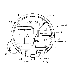
even under calm
seas and low wind conditions..
[0059] In another embodiment of the invention, the conveyor intersects with
the cable
being paid out by the cable engine. At the intersection, a seismic unit is
attached to the cable
and the attached unit is subsequently released into the water. A cable grabber
downstream
from the attachment station is used to securely clamp the cable prior to
attachment of a unit,
thereby removing upstream line tension during attachment of the unit to the
cable. The cable
grabber may include a release system requiring an operator to use both hands
in order to open
the grabber, thereby minimizing danger to the operator when the unit is
released and the
upstream cable is again placed under tension.
[0060] With respect to tension in the cable, the cable is sectioned and the
cable sections are
attached to one another utilizing a uniquely designed, break-away connector.
The connector
is comprised of first and second fittings that nest into each other. A shear
pin is inserted
through the nested fittings to secure the fitting together. Each fitting is
attached to the end of
a cable section such that when the fittings are secured together, the cable
sections form a
longer length of cable. If the tension in the cable become greater than the
shear limit of the
shear pin, the shear pin with break away and the cable will separate.
[0061] Furthermore, while one embodiment of the invention utilizes a clamping
mechanism
that permits units to be clamped directly on a length of cable, another
embodiment of the
invention utilizes a sleeve attached to the cable. The clamping mechanism
secures to the
sleeve which is bounded by overmolded shoulders. Rather than attaching
shoulders between
adjacent lengths of cable as is common in the prior art, the sleeve of the
invention can be
clamped or placed around a length of cable and secured in place without
cutting the cable. In
the embodiment, the sleeve is secured to the cable by inserting pins through
the sleeve and
cable in the x and y planes perpendicular to the axis of the cable. Shoulders
are molded over
the pins at the ends of each sleeve. While the overmolding on opposite ends of
the sleeve can
19
CA 02897395 2015-07-06
WO 2014/110024
PCT/US2014/010472
be used to define an attachment area along the sleeve, the sleeve may include
flared ends that
further define such attachment area.
100621 In one aspect, a method is disclosed of performing a seismic survey
including:
deploying nodal seismic sensors at positions in a survey region; activating a
plurality of
seismic sources; and using the nodal seismic sensors to record seismic signals
generated in
response to the activation of the plurality of signals.
[0063] In some embodiments, at least some of the nodal seismic sensors record
blended
seismic signals.
[0064] In some embodiments, the step of activating a plurality of seismic
sources includes
repeatedly activating at least two of the seismic sources at times separated
by a variable
dither time.
[0065] In some embodiments, the dither time varies randomly or pseudo-
randomly.
[0066] In some embodiments, at least some of the nodes are configured to
continuously
record seismic signals to generate seismic data during the step of repeatedly
activating at least
two of the seismic sources.
[0067] Some embodiments include retrieving the continuously recorded seismic
data
acquired during the step of repeatedly activating at least two of the seismic
sources; and
processing the retrieved data to generate seismic gather data indicative of at
least one
common receiver gather.
[0068] Some embodiments include de-blending the seismic gather data.
[0069] In some embodiments, de-blending the seismic gather data includes
enhancing data
corresponding to activation of a first one of the seismic sources while
diminishing data
corresponding to activation of another one of the seismic sources.
[0070] In some embodiments, enhancing data corresponding to activation of the
first one of
the seismic sources includes coherently combining data corresponding to
multiple activations
of the first one of the seismic sources using coherent data from at least a
portion of the
plurality of sensor nodes.
CA 02897395 2015-07-06
WO 2014/110024
PCT/US2014/010472
[0071] In some embodiments, diminishing data corresponding to activation of
the second
one of the seismic sources includes incoherently combining data corresponding
to multiple
activations of the second one of the seismic sources using incoherent data
from at least a
portion of the plurality of sensor nodes.
[0072] In some embodiments, at least a portion of the nodal seismic sensors
includes ocean
bottom sensors.
[0073] Some embodiments include comprising deploying at least some of the
ocean bottom
sensors using a remotely operated vehicle.
[0074] Some embodiments include deploying at least some of the ocean bottom
sensors
using a node-on-a-rope system.
[0075] In some embodiments the nodal seismic sensors are synchronized to
standard time at
the time they deployed.
[0076] In some embodiments, the nodal seismic sensors are synchronized to
standard time
at the time they are recovered.
[0077] In some embodiments, the nodal seismic sensors are synchronized to
standard time
at the time they while they are deployed.
[0078] In some embodiments, at least one of the nodal seismic sensors include
a UPS
receiver used to synchronize the sensor to standard time at the time they
while the sensor is
deployed.
[0079] In some embodiments, at least some of the nodal seismic sensors are
deployed in a
marine environment at a depth greater than 100 m, 500 m,1000 m.
[0080] In some embodiments, at least some of the nodal seismic sensors
continuously
record seismic data during deployment.
100811 In some embodiments, activating a plurality of seismic sources
includes: obtaining a
plurality of marine vessels, each vessel configured to transport at least one
of the plurality of
seismic sources; and using the marine vessels to activate the seismic sources
at a plurality of
selected location.
21
CA 02897395 2015-07-06
WO 2014/110024
PCT/1JS2014/010472
[0082] In some embodiments, at least one of the nodal seismic sensors
includes: a case; at
least one seismic sensor disposed within the case; a clock disposed within
said case; a power
source disposed within the case; and a seismic data recorder disposed within
the case.
[0083] In some embodiments, the at least one seismic sensor includes a
geophone,
hydrophone, accelerometer, or combinations thereof.
[0084] In some embodiments, at least one seismic source includes at least one
air gun.
[0085] In some embodiments, at least one of seismic source includes at least
one selected
from the list consisting of: a weight drop device; a seismic vibrator device;
and an explosive
source.
[0086] In some embodiments, the step of activating a plurality of seismic
sources includes
modulating an output of each seismic source with a respective modulation
signature
indicative of the identity of the seismic source.
[0087] Some embodiment include using the record seismic signals to generate
survey data
indicative of subsurface geological features in the survey region.
[0088] Some embodiments include outputting the survey data.
[0089] Various embodiments may include any of the above described elements,
either alone
or in any suitable combination,
22
CA 02897395 2015-07-06
WO 2014/110024
PCT/US2014/010472
BRIEF DESCRIPTION OF THE DRAWINGS
[0090] FIG. 1 is a cut-away top view of the seismic recorder unit of the
current invention.
[0091] FIG. 2 is a front side view of the unit of FIG. 1.
[0092] FIG. 3 is aback side view of the unit of FIG. 1.
[0093] FIG. 4 is atop view of the unit of FIG. 1.
[0094] FIG. 5 is a back side view of the unit with a cross-section of the
rounded bumper.
[0095] FIG. 6 is a back side view of the unit with a cross-section of a wedge
bumper.
[0096] FIG. 7 is a top view of the unit with the wedge bumper of FIG. 6.
[0097] FIG. 8 is elevated view of the unit with a hinged flipper.
[0098] FIG. 9 illustrates an over-the-stem pod retrieval method.
[0099] FIG. 10 illustrates multiple units attached to a non-rigid line during
deployment.
[0100] FIG. 11 illustrates a system for conducting a seismic survey with
multiple seismic
sources featuring a node-on-a-rope deployment technique.
[0101] FIG. 12 illustrates a system for conducting a seismic survey with
multiple seismic
sources featuring an ROV based deployment technique.
[0102] FIG. 13 is a flow diagram for a method of conducting a seismic survey
with multiple
seismic sources.
[0103] FIG. 14 is a flow diagram for a method of processing data collected in
a seismic
survey with multiple seismic sources.
[0104] FIG. 15 is a graph showing an example of data collected as part of a
seismic survey
with multiple seismic sources.
[0105] FIG. 16 is a graph showing the result of deblending the data of FIG.
15.
[0106] FIG. 17 illustrates a common receiver gather with an ocean bottom node.
23
CA 02897395 2015-07-06
WO 2014/110024
PCT/US2014/010472
DETAILED DESCRIPTION OF THE PREFERRED EMBODIMENTS
[0107] In the detailed description of the invention, like numerals are
employed to designate
like parts throughout, various items of equipment, such as fasteners,
fittings, etc., may be
omitted to simplify the description. However, those skilled in the art will
realize that such
conventional equipment can be employed as desired.
[0108] With reference to FIG. 1, there is shown a seismic data collection
system or pod 10
of the invention. Pod 10 is comprised of a water tight case 12 having a wall
14 defining an
internal, water-tight compartment 16. Disposed within compartment 16 is at
least one
geophone 18, a clock 20, a power source 22, a control mechanism 23 and a
seismic data
recorder 24. In the embodiment, pod 10 is self-contained such that power
source 22 meets all
of the power requirements of pod 10. Likewise, control mechanism 23 provides
all control
functions for pod 10 eliminating the need for external control communications.
Pod 10 is
weighted to have a negative buoyancy so that it will sink towards the ocean
floor when
deployed in a water column.
[0109] Those skilled in the art will appreciate that pod 10 is a self-
contained seismic data
collection system which requires no external communication or control in order
to record
seismic signals. It will be further noted that geophone 18 is internally
mounted within pod 10
and thus requires no external wiring or connection. It has been determined
that utilizing the
case design described in more detail below, geophone 18 is effectively coupled
to the ocean
floor such that seismic data transmitted through pod 10 to geophone 18 is not
corrupted by
interference.
101101 While the basic elements have been described above, pod 10 may also
include a
compass 36 and a tilt meter 38. Furthermore, in the preferred embodiment,
geophone 18 is a
geophone package comprised of three geophones to detect seismic waves in each
of the x, y
and z axes. Unless specifically indicated, all references to geophones
utilized in the invention
include conventional geophones as well as other known devices for detecting
seismic wave
activity, including without limitation, accelerometers.
[0111] In another embodiment of the invention, it has been found advantageous
to utilize
four geophones positioned in a tetrahedral configuration such that each
geophone measures
data in multiple planes. In a standard three dimensions configuration, three
geophones are
positioned 900 apart from each other and each geophone measures signal in a
single x, y or z
24
CA 02897395 2015-07-06
WO 2014/110024
PCT/US2014/010472
plane. In a four geophone configuration, the geophones are oriented
perpendicular to the
plane of the tetrahedral faces so that each geophone measures portions of
multiple planes in
the x, y, z coordinate system. For example, one geophone may measure seismic
data in the x-
plane and z-plane. Geophone configurations of four or more geophones are
desirable because
they provide for redundancy in the seismic unit in the event of failure of a
geophone in a
particular plane. None of the prior art OBS systems have utilized four or more
geophones to
detect seismic data in the manner.
[0112] In one important aspect of the invention, clock 20 is a rubidium clock.
Heretofore,
rubidium clocks have not been used in seismic exploration due in part to the
expense when
compared to traditional crystal driven clocks. However, because the pod 10 of
the invention
is intended to operate most effectively in one of several orientations, it is
necessary to utilize
a clock that in not susceptible to orientation effects which can inhibit
operation of traditional
prior art crystal clocks. Furthermore, rubidium clocks are less susceptible to
temperature and
gravitational effects that can inhibit operation of prior art clocks in ocean
environments.
[0113] Power source 22 is preferably a lithium ion battery. To the extent
prior art OBS
systems have utilized on-board batteries, as opposed to external cabling to
supply power, the
prior art batteries have been lead-acid, alkaline or non-rechargeable
batteries.
101141 None of the prior art OBS systems have utilized lithium ion batteries.
However,
because of the sealed, self-contained nature of the pod of the invention, it
is desirable to
utilize a battery, such as the lithium ion type, that does not vent fumes and
are easily
rechargeable.
[0115] In FIGS. 2 and 3, one of the unique features of pod 10 can be
appreciated, namely
the low profile configuration of pod 10. Specifically, case 12 comprises a
first plate 26 and a
second plate 28 jointed together along their peripheries by wall 14. In one
embodiment plates
26 and 28 are disk shaped, such that the overall shape of case 12 is that of a
wheel. In any
event, as can be appreciated, each plate 26, 28 is characterized by a width
(W) and wall 14 is
characterized by a height (H), wherein the width W of plates 26, 28 is greater
than the height
of the wall. Of course, to the extent plates 26, 28 are disk shaped, then any
references to
width W should be replaced by a diameter D. However, for purposes of the low
profile
description, whether case 12 is circular in shape and characterized by a
diameter D or
otherwise characterized by a height H, the low profile characteristic is the
same. While not
CA 02897395 2015-07-06
WO 2014/110024
PCT/US2014/010472
limiting the overall low profile, in one embodiment, the height H is no more
than 50% of the
width W or diameter D. In one non-limiting example, the height H of pod 10 is
approximately 6.5 inches and the width/diameter of pod 10 is approximately
18.5 inches.
[0116] As shown in the drawings, the pod 10 is substantially externally
symmetrical about
its x and y axes, such that, when deployed, pod 10 can settle on either side
30, 32 and still
effectively couple to the ocean bottom. Thus, the orientation of pod 10
becomes much less of
a concern as compared to prior art OBS systems designed to settle on the
bottom in only one
"upright" position. Furthermore, because of the narrow profile of pod 10, its
balance is
generally unstable on edge 34. Thus, to the extent pod 10 touches down on the
ocean bottom
on edge 34, the pod 10 will tip over and settle on one of the two faces 30,
32.
[0117] Pod 10 also includes internal ribbing 33 used to support plates 26, 28
as pod 10 is
subjected to the high pressures characteristic of an ocean environment.
Ribbing 33 prevents
any "rattle" or movement of plates 26, 28 that could otherwise interfere with
seismic wave
detection. Unlike the prior art, pod 10 as described herein is effectively a
casing for the
geophones such that a seismic wave can pass undistorted through the pod's
plate to geophone
18. In this regard, because of the low profile and rigid nature of pod 10, the
attachment point
of geophone 18 within case 12 becomes of less consequence and the problems
associated
with prior art designs are overcome.
[0118] Each unit may include a unique identification means, such as a radio
frequency
identification (RFTD) tag 40 or similar identification indicia to permit
tracking of the
individual units as they are handled on the deck in the manner described
below. Likewise,
each unit may include an acoustical location transducer 42 which permits the
unit's location
on the ocean floor to be determined.
[0119] FIG. 1 also shows a hydrophone 44 to permit measurement of pressure and
a
connector 46 for permitting communication with pod 10 When pod 10 is on deck
or
otherwise disposed in a rack as described below. Connector 46 may be a
standard pin
connector or may be an infrared or similar connector that requires no hard
wiring in order to
communicate with pod 10. Via connector 46, pod 10 may be serviced without
removing one
of plates 26, 28 or otherwise opening case 12. Specifically, connector 46
permits quality
control tests to be run, recorded seismic data to be extracted, clock 20 to be
synchronized and
power source 22 to be recharged, Because connector 46 is only utilized above
the water, a
26
CA 02897395 2015-07-06
WO 2014/110024
PCT/US2014/010472
water tight, pressure resistant connector cap 47 may also be provided to
protect connector 46.
Utilizing such a connector cap 47, connector 46 may be any standard connector
that satisfies
the desired functions of the pod. Connector 46 need not be of the type
normally required of
external connectors subjected to high pressure, corrosive environments.
[0120] Finally, shown in FIG. 1 is an optional attachment bracket 48 for
clamping or
otherwise grasping and manipulating pod 10. Bracket 48 is positioned on case
12 so that the
radial angle between bracket 48 and any hardware that may be extending from
pod 10, such
as transducer 42 or hydrophone 44 is obtuse or acute. In the embodiment shown,
the angle is
acute. Specifically, it is common that upon deployment or retrieval of devices
such as pod 10,
such devices may bang against the side of the ship or other equipment as the
pods are
manipulated, potentially damaging hardware that protrudes from the devices. By
positioning
bracket 48 on the periphery of case 12 so that the radial axis extending from
the center of
case 12 through bracket 48 is less than 900 separated from the radial axis
extending from the
center of case 12 through transducer 42, the likelihood of damage to this
hardware is
diminished.
[0121] In one embodiment of the invention, rather than incorporating an
attachment bracket
48, a latching mechanism is attached to wall 14, again, preferably, in an
position to minimize
damage to equipment protruding from pod 10. One effective latching mechanism
is an over-
center latching mechanism having opposing jaws that can be opened and closed
to permit the
units to be attached to a cable for deployment. The latching mechanism may
further be
attached askew to wall 14 so that the major axis of the latching mechanism and
the z-axis of
the pod 10 do not intersect. Again, such an orientation further protects
hardware protruding
from pod 1 0.
[0122] In FIG. 4, the external surface 50 of one or both of plates 26, 28 is
illustrated.
Specifically, surface 50 may be provided with projections 51, such as ridges
or grooves, to
enhance coupling between pod 10 and the ocean floor. In the embodiment shown,
the
projections 51 form a chevron pattern on surface 50.
[0123] Also shown on FIGS. 4 and 5 is an attachment bracket 54 which may be
incorporated for clamping or otherwise grasping and manipulating pod 10 so
that plates 26,
28 remain substantially horizontal as pod 10 is lowered through a water column
by a cable
27
CA 02897395 2015-07-06
WO 2014/110024
PCT/US2014/010472
attached bracket 54. As such, bracket 54 may be axially centered on one of
plates 26, 28 or
otherwise positioned on one of plates 26, 28 above the center of gravity of
pod 10.
101241 Turning to FIGS. 4-8, one of the aspects of the invention is the
incorporation of a
bumper, generally numbered as bumper 52, around the pod 10. FIGS. 4-8
illustrate three
different configurations of bumper 52, wherein the configurations are referred
to as bumper
52a, bumper 52b and bumper 52c. In any event, bumper 52 has several functions.
First, it
may be shaped to urge pod 10 onto one of the two faces 30, 32 when pod 10
touches down on
the ocean bottom on edge 34. Bumper 52 also functions to protect pod 10 and
any external
devices, such as transducer 42, which may be protruding from case 12. Finally,
the bumper
may be of a shape that inhibits pod 10 from becoming entangled by shrimping
nets and
shrimping drag or "tickle" chains. In any case, bumper 52 may serve some or
all of these
functions.
[0125] As stated above, bumper 52 may have several designs. In FIG. 5, bumper
52a is
shown in cut-away disposed around case 12, while in FIG. 4, a bumper 52a is
seen in a top
view of pod 10. Specifically, bumper 52a is shown as having a rounded or
curved cross
section 55. As shown, bumper 52a includes a shoulder 56 which fits into a
groove 58 defined
around the periphery of case 12. A portion 60 of bumper 52a extends beyond the
periphery of
case 12, thereby protecting edge 34 of case 12. Due to the rounded nature of
the bumper 52a,
pod 10 will roll or tilt onto a coupling surface of plates 26, 28 if pod 10
begins to settle on the
ocean floor so that plates 26, 28 are perpendicular with the ocean floor.
Furthermore, bumper
52a will function to protect pod 10 from shock and to protect personnel during
handling of
pod 10.
[0126] An alternate bumper profile is shown in FIGS. 6 and 7 in which bumper
52b has a
wedge-shaped cross-section 62. Again, bumper 52b includes a shoulder 56 which
fits into a
groove 58 defined around the periphery of case 12. A portion 64 of bumper 52b
extends
beyond the periphery of case 12, thereby protecting plates 26, 28 and edge 34
of case 12. The
bumper 52b illustrated in FIGS. 6 and 7 also includes cavities 66 which can be
utilized as
handholds for grasping and manipulating pod 10. In the embodiment of 52b, it
can be
appreciated that it is desirable to orient pod 10 having bumper 52b on the
ocean floor so that
the wedge of bumper 52b faces down. Thus, for this embodiment, plate 28 is
considered the
top of pod 10 and plate 26 is considered the bottom of pod 10.
28
CA 02897395 2015-07-06
WO 2014/110024
PCT/US2014/010472
[0127] In the bumper 52b embodiment of FIGS. 6 and 7, an additional bumper
portion 68 is
shown mounted on top plate 28, bumper portion 68 has a rounded cross-section
70 that
transitions into wedge-shaped cross-section 62. In one embodiment, glass beads
may molded
or otherwise incorporated into bumper portion 68 to increase the buoyancy of
bumper portion
68. By increasing the buoyancy at the top of pod 10, this insures that pod 10
will be properly
oriented, i.e., so that wedge shaped bumper 52b faces down, as pod 10 passes
through a water
column and settles on the ocean floor.
[0128] To the extent a chain or other line is pulled against pod 10 when it is
coupled to the
ocean floor, the chain will simply slide along the wedge-shaped surface of
bumper 52b and
up over the top of pod 10. Bumper portion 68 further prevents such a chain or
line from
snagging or catching on any equipment which may be protruding from the upward-
facing
plate surface of pod 10.
[0129] Still yet another embodiment of bumper 52 is illustrated in FIG. 8 in
which bumper
52c is comprised of a flipper or wedge 72 having a narrow end 74 and a wide
end 76. Wide
end 76 is fitted and hinged between two brackets 78 attached to wall 14 of
case 12.
Preferably, brackets 78 are shaped so that their out edge 80 forms a
substantially smooth
transition surface with the surface of wedge 72. During deployment, pod 10 can
settle on
either surface 26, 28 and the hinged wedge 72 will flap down against the ocean
floor, forming
a ramp or skirt over which a shrimper chain or similar line will ride when
pulled against pod
10. In this way bumper 52c will urge the chain over the top of pod 10
preventing the chain
from snagging or catching pod 10.
[0130] One function of the seismic data recording unit of the invention is the
continuous
operation of the unit. In this aspect of the invention, data acquisition is
initiated prior to
positioning of the unit on the earth' s surface. In one preferred embodiment,
a marine seismic
unit is activated and begins acquiring data prior to deployment in the water.
Systems that are
activated and begin acquiring data prior to deployment are thereby stabilized
prior to the time
when signal detection is desired. This minimizes the likelihood that an
altered state in
electronics operation will disrupt signal detection. Of course, in the case of
a continuous data
acquisition unit such as this, the novelty lies in the "continuous" nature of
the unit and such
function is applicable whether on land or in a marine environment.
29
CA 02897395 2015-07-06
WO 2014/110024
PCT/US2014/010472
[0131] In a similar embodiment, data recording is initiated prior to
positioning along a
receiver line. For example, a marine seismic data recording unit is activated
while still on the
deployment vessel and begins acquiring data prior to deployment in the water.
Again, this
permits units to stabilize prior to the time signal recording is desired. To
this end, one
component of system stabilization is clock stabilization. Of the various
components of the
system, it is well known that clocks typically take a long time to stabilize.
Thus, in one
embodiment of the invention, whether the unit is continuously detecting data
or continuously
recording data, the clock always remains on.
[0132] In either of the preceding two methods, the unit can be utilized in
several cycles of
deployment and retrieval without interrupting the continuous operation of the
unit. Thus, for
example, prior to deployment, recording is initiated. The device is deployed,
retrieved and
redeployed, all while recording is continued. As long as memory is sufficient,
this continuous
recording during multiple cycles of deployment and redeployment can be
maintained.
[0133] In this regard, to the extent the seismic data unit includes wrap
around memory, it
can continuously record even when not in use in seismic detection. Thus, in
addition to the
advantages described above, initiation or start instructions become
unnecessary. Further,
continuous recording utilizing wrap around memory functions as a back-up for
data acquired
from prior recordings until such time as the prior data is written over. An
additional
advantage is that the device is ready for deployment at any time as long as
the clock is
synchronized.
[0134] To the extent recording is continued after a unit has been retrieved,
routine
operations such as data collection, quality control tests and battery charging
can take place
without interrupting recording. One benefit of such a system is that the
device can be utilized
to record quality control test data rather than seismic data when conducting
quality control
tests. In other words, the data input changes from seismic data to quality
control data. Once
quality control is complete, the device may resume recording seismic data or
other desired
data, such as data related to position and timing.
[0135] In one preferred embodiment of the invention, a marine seismic unit
includes an
inertial navigation system to measure the unit's x, y and z position
information as the unit is
passing through the water column and settles on the ocean floor. Generally,
such a system
measures movement in each of the x, y and z dimensions as well as angular
movement
CA 02897395 2015-07-06
WO 2014/110024
PCT/US2014/010472
around each x, y and z axis. In other words, the system measures the six
degrees of freedom
of the unit as it travels from the vessel to the ocean floor, and utilizes
such measurement
information to determine location on the ocean floor. In the preferred
embodiment, such x, y
and z dimensional information can be determined utilizing accelerometers.
Angular
orientation, i.e., tilt and direction, information can be determined utilizing
a tilt meter and a
compass or other orientation devices, such as gyroscopes. In one embodiment of
the
invention, three accelerometers and three gyroscopes are utilized to generate
the inertial
navigation data used to determine the unit's ocean floor position.
[0136] In any event, by combining accelerometer and the tilt and direction
information as a
function of time with the unit's initial position and velocity at the time it
is discharged into
the water column, the travel path of the unit through the water column can be
determined.
More importantly, the location of the unit at the bottom of the water column,
i.e., the location
of the unit on the ocean floor, can be determined. Time sampling will occur at
appropriate
intervals to yield the accuracy needed. Time sampling between various
measurement
components may vary. For example, data from the compass, used to measure
direction, and
the tilt meter, used to measure tilt, may be, sampled more slowly than data
from the
accelerometers. Heretofore, no other marine seismic unit has utilized one or
more
accelerometers to determine location in this way. In this regard, the method
and system
replaces the need to determine ocean floor location utilizing other
techniques, such as through
acoustical location transducers or the like.
[0137] Notwithstanding the foregoing, this position determination method
functions
particularly well with the above described continuous recording method.
Because a unit is
already recording data as it is discharged into the top of the water column,
x, y and z
positional information is easily recorded on the unit and becomes part of the
unit's complete
data record.
[0138] The invention also provides for a unique retrieval method for OBS units
300
attached to a cable 302, as illustrated in FIG. 9. Specifically, it has been
found that retrieving
cable 302 over the trailing end 304 (generally the stem) of a vessel 306 as
the vessel moves
leading end 30S (often the vessel bow) first down a cable 302 in the direction
of the cable
minimizes dragging of the cable on the ocean floor 310 as the cable 302 is
taken up and
prevents undue tension or "pulling" of the cable 302 common in the prior art
retrieval
technique. Specifically, the water drag on the OBS units and cable in the
method of the
31
CA 02897395 2015-07-06
WO 2014/110024
PCT/US2014/010472
invention causes the cable 302 to parachute or billow out behind vessel 306,
as shown at 312,
utilizing the water column as a shock absorber and minimizing undue tension.
101391 In this method, regulation of the speed of the vessel 306 is not as
critical as in the
prior art over-the-bow retrieval method. Furthermore, because the cable 302 is
billowed out
312 in the water behind the vessel as the vessel moves in the opposite
direction from the
billow, the cable is less likely to become entangled in the vessel's
propellers as may occur
using the prior art method. Of course, those skilled in the art will
understand that in the
method of the invention, cable can be taken up over the bow or the stern of
the vessel as long
as the vessel is moving in a direction along the cable and the cable is being
taken up by the
trailing end of the vessel.
[0140] In any event, a flotation release system 314 may also be attached to
the cable,
generally at one or both ends of the deployed cable, to cause at least a
portion of the cable to
rise to the surface where it can be easily snagged for retrieval utilizing the
above described
method. Such a system is well known in the art and may include a flotation
device that is
released from near the ocean floor at the desired time of retrieval or a
flotation device that
floats on the water surface but remains attached to the cable while deployed.
[0141] The non-rigid cable of the invention is also incorporated in a unique
deployment
method for the pods, as illustrated in FIG. 10. Specifically, at least two OBS
units 400 are
tethered together using a non-rigid cable 402. The cable 402 and units 400 are
deployed into
a water column 404. Because the units 400 are of a much greater negative
buoyancy than the
nonrigid cable 402, the units will have a tendency to sink through the water
column ahead of
the cable such that the cable segment adjoining two units parachutes between
the two units as
shown at 406, The drag of the cable down through the water column functions as
a break,
slowing the descent of the units and permitting the placement of the units on
the ocean floor
408 to be more readily controlled. Specifically, the parachuting effect
permits control of the
orientation of units such as those outfitted with the wedge shaped bumper
illustrated in FIGS.
6 and 7. Furthermore, the non-rigid cable cause the unit to gently settle on
the ocean floor,
allowing for consistent coupling of the units to the ocean floor.
[0142] This is an improvement over the prior art methods because the prior art
methods
utilize a rigid or semi-rigid cable for deployment of OBS units. Such cable
has a tendency to
sink quickly through the water column along with the units. In other words,
such cables do
32
CA 02897395 2015-07-06
WO 2014/110024
PCT/US2014/010472
not have the same drag characteristics as the lighter weight, non-rigid cable
of the invention.
In cable and OBS units utilizing this prior art method, the orientation of
individual units is
much more likely to destabilize, e.g., wobble off course or flip over, as the
unit quickly
passes through the water column.
[0143] An additional benefit to the deployment method of the invention is that
the non-rigid
cable permits slack to form between adjacent units, both during deployment and
once settled
on the ocean floor. In fact, it has been found that during general deployment
operations such
as described above, the length of the non-rigid cable between two units will
generally be
much greater than the actual spacing between the units once resting on the
ocean floor. In
other words, once settled on the ocean floor, there may be a great deal of
slack in the non-
rigid cable between adjacent units. For this reason, the non-rigid cable of
the invention is not
utilized to space units apart from one another. In any event, a vessel
operator can utilize the
slack that forms in the non-rigid cable to cause correction to a receiver line
as it is being laid.
Specifically, if a deployment vessel drifts or otherwise causes a receiver
line being laid to be
positioned off of the desired receiver line, the vessel at the surface can
reposition to cause the
remainder of the non-rigid cable and attached units to begin settling back on
the desired
receiver line. The slack in the cable resulting from the non-rigid nature of
the cable permits
the operator to get back on line and cause the remainder of the individual
units to settle in
approximately their desired location along the intended line, In contrast, if
such units were
attached to a rigid or semi-rigid cable, the cable would not have any
adjustment slack and the
remainder of the units, while perhaps positioned along the desired receiver
line, would not be
positioned in the desired location along the receiver line. Furthermore, once
the units 400 are
in position on the ocean floor, the cable 402 between them is slack, as shown
at 410. This
"decouples" individual units from one another and prevents strumming or
transmission of
undesired noise along the cable.
[0144] To the extent clock 20 is a crystal clock, information from the tilt
meter 38 may be
used to correct for gravitational effects on clock timing. In the prior art,
tilt meter information
has only been used to correct seismic data. Other than crystal clock
corrections to account for
temperature effects, no other type of crystal corrections have been made to
such clocks. Thus,
one aspect of the invention utilizes tilt meter information to correct
inaccuracies in the clock
timing arising from gravitational effects acting on the crystal clock. Such
clock correction can
33
CA 02897395 2015-07-06
WO 2014/110024
PCT/US2014/010472
be carried out on-board the pod at or near the time of data recording, or
applied to the data
once the data has been extracted from the pod.
101451 Likewise, information from the tilt meter 38 can be used to apply
mathematical
gimballing to the seismic data. To the extent seismic data has been corrected
in the prior art
to adjust for orientation, such correction has been based on mechanical
gimbals installed on
board the prior art OBS systems. However, a typical mechanical gimbal can
cause
deterioration in the data fidelity due to dampening of the gimbal in its
carriage. In one aspect
of the invention, it has been determined that a non-gimballed, mathematical
correction, or
"mathematical gimballing" is desirable over the gimballing methods of the
prior art. Thus,
the invention may utilize tilt meter information to mathematically adjust the
seismic data to
account for vertical orientation of the pod. Such mathematical gimballing can
he carried out
on-board the pod at or near the time of data recording, or may be applied to
data once it has
been extracted from the pod.
[0146] In addition, information from compass 36 can be used to further refine
the
mathematical gimballing to account for rotational orientation of the unit.
Specifically,
compass data can be incorporated with the tilt meter data in mathematical
gimballing to more
fully correct seismic data for effects arising from orientation of a pod.
Simultaneous Shooting With Nodal Acquisition
101471 In some embodiments, seismic surveys may be performed using seismometer
packages ("pods," "nodes"), e.g., of the type described herein, to record
seismic signals
generated in response to multiple seismic sources. For example, as discussed
in greater detail
below, ocean bottom sensor nodes may be used to record seismic signals
generated in
response to repeated activation of multiple seismic sources, e.g., air gun
sources towed by
multiple vessels, at selected times and locations. These activations are
sometimes referred to
as "shots". The ocean bottom sensor nodes are deployed at selected locations,
and may be
used to continuously record seismic data during the activation of the multiple
sources, with
the nodes later retrieved, and the seismic data extracted for processing.
[0148] The use of multiple sources may be advantageous, e.g., in allowing for
a survey plan
with a given number of shot points to be completed in less time than would be
possible using
a single source. However, the use of multiple sources may lead to
complications in data
processing. For example, a given sensor node may receive seismic energy
originating from
34
CA 02897395 2015-07-06
WO 2014/110024
PCT/US2014/010472
multiple sources at the same time, resulting in "blended" data. Accordingly, a
survey where
this occurs may be referred to as a "simultaneous shooting" survey. Note that
while the term
"simultaneous shooting" is used to discuss this approach to seismic surveying,
in practice the
shots tend to be only substantially simultaneous, but may be generally (e.g.,
as described in
greater detail below) not precisely simultaneous. In the context of this
application, shots from
different sources that are substantially simultaneous are fired closely enough
together in time
that at least one node being used in the seismic survey to collect seismic
data will receive a
signal that for at least some period of time represents seismic data caused by
both of the
shots. Such a signal may be referred to as a "blended seismic signal."
[0149] In some cases, blended data recorded in response to a blended seismic
signal may be
unsuitable, e.g., when using processing techniques developed under the
assumption of a
single source (as is the case with many conventional seismic processing
techniques).
[0150] Accordingly, in some embodiments, the seismic survey may be conducted
in a
manner that allows for the data to be processed to separate out signal from
each of multiple
sources, a process referred to generally as "deblending". For example, in some
embodiments,
the relation in time between shots may be varied (e.g., randomly, pseudo-
randomly, or with a
selected timing function). This timing relationship may then be used to
deblend the recorded
seismic signal. For example, as explained in greater detail below, when this
type of timing
relationship is provided, combining data from multiple shots for a given
receiver may cause
the seismic signal from one source to combine coherently (thereby enhancing
the signal from
this source in the combined data), while causing the seismic signal from
another source or
sources to combine incoherently (thereby diminishing the signal from this
source in the
combined data). In some embodiments, the signal from the other sources may be
reduced by,
e.g., 50%, 75%, 90%, 95%, 99% or more. In some embodiments, this allows the
data to be
substantially or completely deblended, thereby allowing the data to undergo
further
processing using techniques designed for non-blended seismic data.
101511 As mentioned above, "simultaneous shooting" may allow for significant
reduction
in acquisition time for a seismic survey. In a case where two sources are
used, the time
required to perform the survey may be reduced dramatically, on the order of a
50% reduction
in time required. If more than two sources are used, the required time may be
reduced even
further. Similarly, when a seismic survey is to be performed within a set
amount of time, a
greater amount of data may be gathered for a particular area, or a greater
area may be
surveyed due to the efficiencies realized with using multiple sources.
[0152] Any of the seismometer packages ("pods," "nodes") described above may
be
employed as part of a seismic survey performed using simultaneous shooting.
For example,
Figs. 11 and 12 illustrate exemplary uses of autonomous ocean bottom nodes for
performing
a seismic survey. These examples and others all may be used in performing a
seismic survey
with simultaneous shooting. While the nodes and sources discussed herein
primarily are
discussed in a marine environment, the principles discussed herein may be
employed in other
contexts, such as land-based sources and nodes (e.g. Vibroseis sources).
[0153] Fig. 11 shows an embodiment where autonomous ocean bottom sensors are
deployed and retrieved to and from a marine vessel using a "node-on-a-rope"
technique. This
deployment process is substantially the same as that described above, e.g., in
reference to
Figs. 9 and 10. Two seismic source vessels are shown which implement a
simultaneous
shooting survey after deployment of the nodes. However, it is to be understood
that in
various embodiments more or fewer source vessels may be used. In some
embodiments, the
deployment vessel may also serve as a source vessel (e.g., where the source
vessel is outfitted
with an air gun).
[0154] Fig. 12 shows an embodiment where autonomous ocean bottom sensors are
deployed and retrieved to and from a marine vessel using a remotely operated
vehicle (ROV)
As shown, a carrier is used to transport sensor nodes to the ocean bottom, for
placement by
the ROV. Advantageously, this approach reduces or eliminates the need for
frequent return
trips by the ROV to the surface for reloading with nodes. This deployment
process may be
substantially the same as that described above, as in e.g., U.S. Patent
Publication No.
2011/0286900, published Nov. 24, 2011, which may be referred to for further
details.
Two seismic source vessels are shown which implement a simultaneous shooting
survey
after deployment of the nodes. However, it is to be understood that in various
embodiments more or fewer source vessels may be used. In some embodiments, the
deployment vessel may also serve as a source vessel (e.g., where the source
vessel is
outfitted with an air gun).
[0155] In various embodiments, the nodes may be deployed using other suitable
techniques.
For example, in some embodiments, the nodes may be dropped from the surface,
and may
36
CA 2897395 2019-10-24
include guidance systems that allow the node to be "flown" through the water
to a selected
location.
[0156] A seismic survey as described herein may include one or more phases in
which
nodes are deployed to collect seismic data and then are retrieved, as well as
one or more
phases in which data is extracted from nodes and processed. An exemplary
process for
acquiring data using these nodes is now described with reference to Fig. 13.
At step 1300, a
multi-source ocean bottom node seismic survey is designed for a specific area.
The use of
multi-sources may benefit a seismic survey by reducing the amount of time it
takes to
conduct or by increasing the amount of data in density or area than can be
acquired in a given
time frame. At step 1310, the nodes are prepared for deployment. The
preparations may
include calibrating the nodes, synchronizing the nodes to a master clock, and
activating the
nodes, e.g., for continuous recording. In some implementations, the
synchronization may
occur at a later, e.g., time after the nodes have been deployed, used to
collect data, and
subsequently retrieved. In such an implementation, the nodes may be
synchronized to the
master clock before shutdown, and the timing of recorded data can be
determined
retroactively based on the difference between the time a particular datum was
recorded and
the time when the node is synchronized. In other implementations, the nodes
may be
synchronized during deployment. For example, in the case of a land based or
shallow water
survey, the nodes may be able to receive a signal such as a global positioning
system signal
that may be used for synchronization. Examples of land based nodes may be
found, e.g.,
in U.S. Patent No. 9,720,116, issued August 1, 2007, U.S. Patent No.
7,561,493, granted
July 14, 2009, and U.S. Patent Pub. No. 2009/0290453 published November 26,
2009
which may be referred to for further details. Similarly, in some embodiments,
ocean
bottom nodes may be synchronized when deployed on the ocean bottom before,
after, or
during the survey. In some embodiments, this may be accomplished using an
underwater
communication link (e.g., an optical link, a wireless link radio link, an
inductive link,
etc.) between the node and an ROV in the vicinity of node. The ROV can provide
a time
signal via a tethered link with the deployment vessel, which may in turn
access a GPS or
other time reference.
[0157] At step 1320, the autonomous ocean bottom nodes are deployed. The nodes
may be
placed at predetermined locations on the ocean floor according to design
considerations of
the seismic survey. In certain implementations, such as the exemplary
implementation shown
37
CA 2897395 2019-10-24
CA 02897395 2015-07-06
WO 2014/110024
PCT/US2014/010472
in Fig. 11, the nodes may be deployed by being trailed off of a boat in
series, each of the
nodes being connected to the linearly immediately preceding and following
nodes by a rope,
cable, etc. As described herein, the nodes are operationally autonomous in
that neither power,
nor data, nor operational instructions are transmitted by the rope, which is
designed strictly
for keeping the nodes physically connected, allowing for simplified deployment
and
collection. In other implementations, such as the exemplary implementation
shown in Fig. 12,
the nodes may be physically independent of one another as well, and may be
deployed
individually by a remote-operated vehicle. One or more nodes may be lowered
from a boat,
for example in a cage or basket, and the remote-operated vehicle may collect
the nodes from
the cage or basket one at a time and distribute them to the desired locations.
In some
implementations, nodes may be placed in especially deep locations, such as
deeper than 1000
meters below the surface of the ocean. However, in various applications any
other suitable
deployment depth may be used, e.g., depths greater than 1 meter, 10 meters,
100 meters, 200
meters, 300 meters, 500 meters, 750 meters, 1000 meters, 2000 meters, or more,
e.g., in the
range of 0-2000 meters or any subrange thereof.
101581 At step 1330, two or more seismic sources ("shots") are activated
substantially
simultaneously. The timing of the shots may be staggered slightly according to
a dithering
strategy to reduce signal artifacting and to facilitate deblending of the
signals collected in
response to the different shots. In some implementations, multiple gun boats
may be
employed, each having at least one seismic source. In other implementations, a
single gun
boat may be employed having multiple seismic sources located in physically
separated
positions. The firing pattern also may include alternating sequentially
between sources. For
example, four seismic sources may be located relative to each other such that
they
substantially are at the four corners of a square. In a first shot of the
firing pattern, two of the
sources may fire, and in a second shot of the firing pattern, the remaining
two sources may
fire. In such an implementation, the pairs of sources may be selected such
that no two
adjacent corners on the square fire together. A precise time and position for
each source
activation is recorded. The time of the source activation can be recorded by a
computer on the
gun boat that has been synchronized to the master clock. The position of the
source activation
may be known from geolocation data such as GPS data. The sources can be
activated such
that the timing relationships or positional relationship between sources is
always changing.
The dither time or position change between substantially simultaneous shots
may be random,
pseudo-random, or a selected function.
38
CA 02897395 2015-07-06
WO 2014/110024
PCT/US2014/010472
[0159] In various embodiments, the deployed nodes can continuously detect,
digitize and
record seismic wavefields (pressure and particle motion) arriving at the ocean
bottom during
the seismic survey (e.g. using one or more seismic sensors such a hydrophone,
geophone,
accelerometer, and combinations thereof). The nodes also can periodically
detect, digitize and
record the orientation in space (e.g., the tilt angle) of the vector motion
sensor. A seismic
survey may include many repetitions of step 1330 to collect data resulting
from firing seismic
sources at many locations throughout the survey area. This data can then be
used to develop
detailed maps and imaging of the subsurface structures in the survey area. The
seismic
sources repeatedly fire during the survey as described, while the gun boat(s)
slowly moves
through the survey area to change the physical locations of the seismic
sources. In some
implementations, the gun boat(s) may travel in straight lines through the
survey area, parallel
to a side of the square area, turn around 180 degrees upon reaching the end of
the area,
relocate slightly to the side, and return in a line parallel to the previously
travelled path. This
movement pattern may be repeated as required until the entire survey area has
been covered.
In other implementations other vessel path geometries are possible as well,
including spiral
and coil patterns, snakelike wavy patterns, and any other known survey
patterns.
[0160] An example of a node collecting data in step 1330, which was described
above, is
shown in Fig. 17. This figure illustrates a common-receiver gather performed
using a an
ocean-bottom node 1701. A series of shots 1702 and fired at regular or
substantially regular
intervals from separate geographic locations at sea level 1703. The sonic
waves 1706 travel
toward and through the ocean floor 1704 and reflect off of a sub-bottom
feature 1705. The
sonic waves 1706 then return toward the ocean floor 1704, where they are
detected and
collected by the ocean-bottom node 1701.
[0161] In some embodiments, the varying time between simultaneous shots may be
provided by causing the shots to occur at varying spatial intervals as the
sources are in motion
along a survey path (e.g., at constant speed). In other embodiments, regular
spatial shot
intervals may be used, but the timing of the simultaneous shots controlled to
be offset with a
time dither as described above.
[0162] In various embodiments, the time dither between shots from two
different sources
may be shorter than the time interval between successive shots by an
individual source.
Exemplary ratios of dither time (i.e., delay between two substantially
simultaneous shots) and
shot interval (i.e., delay between two shots from a single source) may be 1/2,
1/5, 1/10, 1/100,
39
CA 02897395 2015-07-06
WO 2014/110024
PCT/US2014/010472
1/1000, 1/10,000 or less. For example, in some typical embodiments, the dither
time may be
on the order of 100 milliseconds, while the shot interval is on the order of a
second, tens of
seconds, a minute, a few minutes, or more.
[0163] In some embodiments, it is advantageous to record the time and location
of all shots,
even if the shots are not part of the production data of the survey (e.g.,
shots taken during
vessel turning operations between survey lines). This allows any blending from
these non-
production shots to be removed from the production data.
[0164] At step 1340, the nodes are retrieved from the ocean bottom after
activation of all
planned seismic sources at all planned locations. In the case of
implementations involving
physical connection such as rope between the nodes, the nodes may be collected
one at a time
by gradually reeling the line in onto the boat. In the case of implementations
involving
physically unconnected nodes, the nodes may be collected by remote-operated
vehicle (ROY)
or autonomously operated vehicle (AUV). The continuously recorded data can
then be
retrieved from each node after it is collected. Measured timing drift also can
be used to
synchronize data from all nodes. Alternatively, the vehicle may extract the
data from the node
while leaving the node in place on the ocean bottom using any suitable type of
communication link (e.g. an underwater optical data transfer link).
101651 An exemplary process for processing acquired data is now described with
reference
to Fig. 14. At step 1410, the data retrieved from the nodes is received. The
step 1420, for
each source, the known source activation times are used to extract and
organize segments of
the continuous recording into common receiver gathers. The length in time of
the extracted
segments can be determined by a maximum depth of interest, corresponding to
the maximum
amount of time it is expected that seismic waves will require to reach the
maximum depth of
interest and return to the sensor. Orientation data also can be used to rotate
the particle
motion data into vertical and desired horizontal components. The coherent
seismic signal in
each common receiver gather (described below) can be used to detect and apply
refinements
in source and receiver positions.
[0166] At step 1430, the data is deblended. The common receiver data can be
deblended
(according to any suitable technique) to produce an approximation of what
would have been
recorded in a single source experiment by exploiting the property that the
desired signal is
coherent and the interfering signal is incoherent. The common receiver gathers
exhibit a
CA 02897395 2015-07-06
WO 2014/110024
PCT/US2014/010472
coherent signal from the source for which the activation times were used to
extract the data,
and they exhibit incoherent interference from all other sources whose
activation occurred in
the same time interval. The coherence between signal time segments exhibited
by the first
source is due to the fact that the time intervals between firing of this
source (during which
time interval the source also is displaced slightly in space to a new location
in the survey
area) are regular (e.g. 1 minute). The incoherence between the other sources
is the result of
the continuously changing random dither time mentioned above. The process can
be
repeated for gathers generated for the other sources, thereby providing
deblended data
corresponding to each source.
[0167] FIG. 15 is a graph showing an example of data collected as part of a
seismic survey
with multiple seismic sources. FIG. 16 is a graph showing the result of
deblending the data of
FIG. 15. In the graph of FIG. 15, the outline of a dual-peak structure is
discernable, but is
blurred by a significant amount of collected signals at other locations in the
graph not
corresponding to the apparent dual-peak structure. This noise is mostly
attributable to the fact
that multiple seismic sources are active at the same time from geographically-
offset locations.
In the graph of FIG. 16, the dual-peak structure is more clearly visible and
the noise in the
graph has been reduced significantly. This reduction in noise by deblending is
made possible
by the fact that the first seismic source is coherent and the second source is
made incoherent
by the application of a small, random time dither. In this example, the two
source lines arc
parallel and about 500 ft apart. At closest approach they come to within 4000
and 4500 ft,
respectively, of the stationary receiver. The shot-to-shot interval on each
line is nominally
82.5 ft (25 m). Typical boat speeds ¨ 4.6 kt (2.36 m/s) produce a nominal time
between shots
of ¨10600 msec. A random shot timing dither of +/- 1000 msec (for both lines)
produces the
incoherency in the interference.
[0168] Note that although one example of deblending is described above, it is
to be
understood that other techniques may be used, e.g., based on the techniques
described in the
references cited in Appendix B. In some embodiments, the deblending may use
other types
of gathers known in the art, such as common midpoint gather, with
appropriately adapted
coherence- or denoising-based techniques applied to deblend the data. In
various
embodiments, suitable deblending techniques may include FK filtering, tau-p
filtering, time-
frequency denoising, FX prediction, singular value decomposition, related
techniques, and
combinations thereof. For example, some embodiments may use the deblending
techniques
described in Hennenfent, G., and F. J. Herrmann, 2008, Simply denoise:
wavefield
41
reconstruction via jittered undersampling: Geophysics, 73, no. 3, V19¨V28, and
Herrmann,
F. J., 2009, Sub-Nyquist sampling and sparsity: how to get more information
from
fewersamples: 79th Annual International Meeting, SEG, Extended Abstracts 28,
3410-3413,
which may be referred to for further details.
[0169] The deblended data may be processed further as if the data acquisition
had been
performed with a single source. Exemplary downstream processes for ocean
bottom node
data include wavefield separation into up-going and down-going components,
spatial
interpolation and regularization, deconvolution, demultiple, velocity
analysis, and migration.
[0170] For example, in the embodiment shown, the data is optionally migrated
at step 1440.
In migrating the data, the deblended sensor data is converted into data
representing spatial
and physical characteristics of the subsurface structures in the area under
survey. At step
1450, the data is stacked. In certain implementations, the data may be stacked
before
migration, whereas other implementations may include only post-stacking
migration, which
is optionally performed at step 21460. Stacking of data involves combining
multiple sources
of data and generating a new data set incorporating the information present
from the various
input data. The data is then transformed at step 1470 to generate mapping
and/or imaging
data representing the subsurface structures in two or three dimensions, such
as may be
suitable for oil and gas exploration.
[0171] Although the examples described above are focused on deblending planned
seismic
source activations, it is to be understood that the techniques may also be
applied to
deblending signal from unplanned seismic source activations (e.g., due to
geological events,
third party activity in or near the survey area, etc.), as long as the time
and spatial location of
the unplanned activation can be at least approximately determined.
[0172] While various inventive embodiments have been described and illustrated
herein,
those of ordinary skill in the art will readily envision a variety of other
means and/or
structures for performing the function and/or obtaining the results and/or one
or more of the
advantages described herein, and each of such variations and/or modifications
is deemed to
be within the scope of the inventive embodiments described herein. More
generally, those
skilled in the art will readily appreciate that all parameters, dimensions,
materials, and
configurations described herein are meant to be exemplary and that the actual
parameters,
dimensions, materials, and/or configurations will depend upon the specific
application or
42
CA 2897395 2019-10-24
CA 02897395 2015-07-06
WO 2014/110024
PCT/US2014/010472
applications for which the inventive teachings is/are used. Those skilled in
the art will
recognize, or be able to ascertain using no more than routine experimentation,
many
equivalents to the specific inventive embodiments described herein. It is,
therefore, to be
understood that the foregoing embodiments are presented by way of example only
and that,
within the scope of the appended claims and equivalents thereto, inventive
embodiments may
be practiced otherwise than as specifically described and claimed. Inventive
embodiments of
the present disclosure are directed to each individual feature, system,
article, material, kit,
and/or method described herein. In addition, any combination of two or more
such features,
systems, articles, materials, kits, and/or methods, if such features, systems,
articles, materials,
kits, and/or methods are not mutually inconsistent, is included within the
inventive scope of
the present disclosure.
[0173] The above-described embodiments can be implemented in any of numerous
ways.
For example, the embodiments may be implemented using hardware, software or a
combination thereof. When implemented in software, the software code can be
executed on
any suitable processor or collection of processors, whether provided in a
single computer or
distributed among multiple computers.
[0174] Also, a computer may have one or more input and output devices. These
devices
can be used, among other things, to present a user interface. Examples of
output devices that
can be used to provide a user interface include printers or display screens
for visual
presentation of output and speakers or other sound generating devices for
audible
presentation of output. Examples of input devices that can be used for a user
interface
include keyboards, and pointing devices, such as mice, touch pads, and
digitizing tablets. As
another example, a computer may receive input information through speech
recognition or in
other audible format.
[0175] Such computers may be interconnected by one or more networks in any
suitable
form, including a local area network or a wide area network, such as an
enterprise network,
and intelligent network (IN) or the Internet. Such networks may be based on
any suitable
technology and may operate according to any suitable protocol and may include
wireless
networks, wired networks or fiber optic networks.
[0176] A computer employed to implement at least a portion of the
functionality described
herein may comprise a memory, one or more processing units (also referred to
herein simply
43
CA 02897395 2015-07-06
WO 2014/110024
PCT/US2014/010472
as "processors"), one or more communication interfaces, one or more display
units, and one
or more user input devices. The memory may comprise any computer-readable
media, and
may store computer instructions (also referred to herein as "processor-
executable
instructions") for implementing the various functionalities described herein.
The processing
unit(s) may be used to execute the instructions. The communication
interface(s) may be
coupled to a wired or wireless network, bus, or other communication means and
may
therefore allow the computer to transmit communications to and/or receive
communications
from other devices. The display unit(s) may be provided, for example, to allow
a user to
view various information in connection with execution of the instructions. The
user input
device(s) may be provided, for example, to allow the user to make manual
adjustments, make
selections, enter data or various other information, and/or interact in any of
a variety of
manners with the processor during execution of the instructions.
[0177] The various methods or processes outlined herein may be coded as
software that is
executable on one or more processors that employ any one of a variety of
operating systems
or platforms. Additionally, such software may be written using any of a number
of suitable
programming languages and/or programming or scripting tools, and also may be
compiled as
executable machine language code or intermediate code that is executed on a
framework or
virtual machine.
101781 In this respect, various inventive concepts may be embodied as a
computer readable
storage medium (or multiple computer readable storage media) (e.g., a computer
memory,
one or more floppy discs, compact discs, optical discs, magnetic tapes, flash
memories,
circuit configurations in Field Programmable Gate Arrays or other
semiconductor devices, or
other non-transitory medium or tangible computer storage medium) encoded with
one or
more programs that, when executed on one or more computers or other
processors, perform
methods that implement the various embodiments of the invention discussed
above. The
computer readable medium or media can be transportable, such that the program
or programs
stored thereon can be loaded onto one or more different computers or other
processors to
implement various aspects of the present invention as discussed above.
[0179] The terms "program" or "software" are used herein in a generic sense to
refer to any
type of computer code or set of computer-executable instructions that can be
employed to
program a computer or other processor to implement various aspects of
embodiments as
discussed above. Additionally, it should be appreciated that according to one
aspect, one or
44
more computer programs that when executed perform methods of the present
invention need
not reside on a single computer or processor, but may be distributed in a
modular fashion
amongst a number of different computers or processors to implement various
aspects of the
present invention.
[0180] Computer-executable instructions may be in many forms, such as program
modules,
executed by one or more computers or other devices. Generally, program modules
include
routines, programs, objects, components, data structures, etc. that perform
particular tasks or
implement particular abstract data types. Typically the functionality of the
program modules
may be combined or distributed as desired in various embodiments.
[0181] Also, data structures may be stored in computer-readable media in any
suitable
form. For simplicity of illustration, data structures may be shown to have
fields that are
related through location in the data structure. Such relationships may
likewise be achieved
by assigning storage for the fields with locations in a computer-readable
medium that convey
relationship between the fields. However, any suitable mechanism may be used
to establish a
relationship between information in fields of a data structure, including
through the use of
pointers, tags or other mechanisms that establish relationship between data
elements.
[0182] Also, various inventive concepts may be embodied as one or more
methods, of
which an example has been provided. The acts performed as part of the method
may be
ordered in any suitable way. Accordingly, embodiments may be constructed in
which acts
are performed in an order different than illustrated, which may include
performing some acts
simultaneously, even though shown as sequential acts in illustrative
embodiments.
The present disclosure is related to the subject matter found in the
references, U.S. and
International Applications listed in Appendix A and Appendix B, which may be
referred
to for further details. All definitions, as defined and used herein, should be
understood to
control over dictionary definitions, and/or ordinary meanings of the defined
terms.
[0183] The indefinite articles "a" and "an," as used herein in the
specification and in the
claims, unless clearly indicated to the contrary, should be understood to mean
"at least one."
[0184] The phrase "and/or," as used herein in the specification and in the
claims, should be
understood to mean "either or both" of the elements so conjoined, i.e.,
elements that are
CA 2897395 2019-10-24
CA 02897395 2015-07-06
WO 2014/110024
PCT/1JS2014/010472
conjunctively present in some cases and disjunctively present in other cases.
Multiple
elements listed with "and/or" should be construed in the same fashion, i.e.,
"one or more" of
the elements so conjoined. Other elements may optionally be present other than
the elements
specifically identified by the "and/or" clause, whether related or unrelated
to those elements
specifically identified. Thus, as a non-limiting example, a reference to "A
and/or B", when
used in conjunction with open-ended language such as "comprising" can refer,
in one
embodiment, to A only (optionally including elements other than B); in another
embodiment,
to B only (optionally including elements other than A); in yet another
embodiment, to both A
and B (optionally including other elements); etc.
[0185] As used herein in the specification and in the claims, "or" should be
understood to
have the same meaning as "and/or" as defined above. For example, when
separating items in
a list, "or" or "and/or" shall be interpreted as being inclusive, i.e., the
inclusion of at least
one, but also including more than one, of a number or list of elements, and,
optionally,
additional unlisted items. Only terms clearly indicated to the contrary, such
as "only one of"
or "exactly one of," or, when used in the claims, "consisting of," will refer
to the inclusion of
exactly one element of a number or list of elements. In general, the term "or"
as used herein
shall only be interpreted as indicating exclusive alternatives (i.e. "one or
the other but not
both") when preceded by terms of exclusivity, such as "either," "one of,"
"only one of," or
"exactly one of." "Consisting essentially of," when used in the claims, shall
have its ordinary
meaning as used in the field of patent law.
[0186] As used herein in the specification and in the claims, the phrase "at
least one," in
reference to a list of one or more elements, should be understood to mean at
least one element
selected from any one or more of the elements in the list of elements, but not
necessarily
including at least one of each and every element specifically listed within
the list of elements
and not excluding any combinations of elements in the list of elements. This
definition also
allows that elements may optionally be present other than the elements
specifically identified
within the list of elements to which the phrase "at least one" refers, whether
related or
unrelated to those elements specifically identified. Thus, as a non-limiting
example, "at least
one of A and B" (or, equivalently, "at least one of A or B," or, equivalently
"at least one of A
and/or B") can refer, in one embodiment, to at least one, optionally including
more than one,
A, with no B present (and optionally including elements other than B); in
another
embodiment, to at least one, optionally including more than one, B, with no A
present (and
46
optionally including elements other than A); in yet another embodiment, to at
least one,
optionally including more than one, A, and at least one, optionally including
more than one,
B (and optionally including other elements); etc.
[0187] In the claims, as well as in the specification above, all transitional
phrases such as
"comprising," "including," "carrying," "having," "containing," "involving,"
"holding,"
"composed of," and the like are to be understood to be open-ended, i.e., to
mean including
but not limited to. Only the transitional phrases "consisting of' and
"consisting essentially
of' shall be closed or semi-closed transitional phrases, respectively.
47
CA 2897395 2019-10-24