Note: Descriptions are shown in the official language in which they were submitted.
CA 02897744 2015-07-09
[DESCRIPTION]
[Invention Title]
METHOD AND DEVICE FOR TRANSMITTING/RECEIVING FRAME IN ACCORDANCE
WITH BANDWIDTH THEREOF IN WLAN SYSTEM
[Technical Field]
[1] The
following description relates to a wireless communication system and, more
particularly, to a method and apparatus for transmitting and receiving a frame
according to a
bandwidth in a Wireless Local Access Network (WLAN) system.
[Background Art]
[2] Various
wireless communication technologies systems have been developed with rapid
development of information communication technologies. WLAN technology from
among
wireless communication technologies allows wireless Internet access at home or
in enterprises or
at a specific service provision region using mobile terminals, such as a
Personal Digital Assistant
(PDA), a laptop computer, a Portable Multimedia Player (PMP), etc. on the
basis of Radio
Frequency (RF) technology.
131 In
order to obviate limited communication speed, one of the advantages of WLAN,
the
recent technical standard has proposed an evolved system capable of increasing
the speed and
reliability of a network while simultaneously extending a coverage region of a
wireless network.
For example, Institute of Electrical and Electronics Engineers (IEEE) 802.11n
enables a data
processing speed to support a maximum high throughput (HT) of 540Mbps. In
addition,
Multiple Input and Multiple Output (MIMO) technology has recently been applied
to both a
transmitter and a receiver so as to minimize transmission errors as well as to
optimize a data
transfer rate.
[Disclosure]
[Technical Problem]
[4]
Machine to Machine (M2M) communication technology has been discussed as next
generation communication technology. A
technical standard for supporting M2M
communication in IEEE 802.11 WLAN has been developed as IEEE 802.11ah. M2M
communication may consider a scenario capable of communicating a small amount
of data
infrequently at low speed in an environment including a large number of
devices.
15] An
object of the present invention is to provide a scheme for preventing resource
waste
and correctly performing frame switching by waiting for a response frame or
deferring channel
access in consideration of a response frame type and/or a channel bandwidth
1
CA 02897744 2015-07-09
1
[6] It is to be understood that technical objects to be achieved by
the present invention are
not limited to the aforementioned technical objects and other technical
objects which are not
mentioned herein will be apparent from the following description to one of
ordinary skill in the
art to which the present invention pertains.
[Technical Solution]
[71 The object of the present invention can be achieved by providing
a method for
performing a response process in a wireless local access network (WLAN)
system, including
transmitting a frame requiring a response frame to a second station (STA) by a
first STA; and
waiting for the response frame during an ACKTimeout interval by the first STA.
The
ACKTimeout interval may be set to a different value according to a preamble
channel bandwidth
type of the frame. A preamble channel bandwidth of the response frame may be
set to a value
equal to the preamble channel bandwidth type of the frame.
18] In another aspect of the present invention, provided herein is a
station (STA) for
performing a response process in a wireless local access network (WLAN)
system, including a
transceiver and a processor. The processor may be configured to transmit a
frame requiring a
response frame to a second STA through the transceiver and wait for the
response frame during
an ACKTimeout interval. The ACKTimeout interval may be set to a different
value according
to a preamble channel bandwidth type of the frame. A preamble channel
bandwidth of the
response frame may be set to a value equal to the preamble channel bandwidth
type of the frame.
[9] According to the embodiments of the present invention, the followings
may be
commonly applied.
[10] If the preamble channel bandwidth type of the frame is a preamble type
of 1MHz, the
ACKTimeout interval may be calculated based on an aPHY-RX-START-Delay value
for a
preamble of 1MHz. The aPHY-RX-START-Delay value may indicate a delay time
until PHY-
RXSTART.indication is issued. The PHY-RXSTART.indication may represent that a
Physical
Layer Convergence Procedure (PLCP) Packet Data Unit (PPDU) having a valid PLCP
header
starts to be received.
[11] If the preamble channel bandwidth type of the frame is a preamble type
of 2MIlz or
more, the ACKTimeout interval may be calculated based on an aPHY-RX-START-
Delay value
for a preamble of 2MHz or more. The aPHY-RX-START-Delay may indicate a delay
time
until PHY-RXSTART.indication is issued. The PHY-RXSTART.indication may
represent that
a Physical Layer Convergence Procedure (PLCP) Packet Data Unit (PPDU) having a
valid PLCP
header starts to be received.
[12] If the frame has a preamble type of 2M1-Iz or more, the response frame
may have a type
other than a preamble type of 1IVPHz.
2
81789720
[13] If the frame has a preamble type of 2MHz or more, the response frame
may have a preamble
type of 2MHz.
[14] If the frame has a preamble type of 1MHz or more, the response frame
may have a preamble
type of 1MHz.
[15] If the response frame is received during the ACKTimeout interval,
transmission of the frame
may be determined to be successful.
[16] If the response frame is not received during the ACKTimeout
interval, transmission of the
frame may be determined to be failure and a backoff procedure is performed by
the first STA when the
ACKTimeout interval is ended.
[17] The frame may be one of a data frame, a Request To Send (RTS) frame,
and a Power Save-
Poll (PS-Poll) frame.
[18] The response frame may be one of an Acknowledgement (ACK) frame, a
Clear To Send
(CTS) frame, and a data frame.
[19] The STA may be an STA operating in a Sub-1GHz (S1G) frequency band.
[19a] According to another aspect of the present disclosure, there is
provided a method for
performing a response process in a wireless local access network (WLAN)
system, the method
comprising: transmitting, by a first station (STA) a frame requiring a
response frame to a second STA;
waiting for the response frame, by the first STA, during an ACKTimeout
interval configured
differently according to whether a preamble channel bandwidth type of the
frame is 1MHz preamble
type or greater than or equal to 2MHz preamble type; and determining, by the
first STA, that
transmission of the frame has failed and performing, by the first STA, a
backoff procedure when the
ACKTimeout interval is ended, wherein the configured ACKTimeout interval is
determined on the
basis of a value of aPHY-RX-START-Delay set to a different value according to
whether the preamble
channel bandwidth type of the frame is 1MHz preamble type or greater than or
equal to 2MHz
preamble type, and wherein a preamble channel bandwidth of the response frame
is set to a value
equal to the preamble channel bandwidth type of the frame.
[196] There is also provided a station (STA) for performing a response
process in a wireless local
access network (WLAN) system, the STA comprising: a transceiver; and a
processor, wherein the
processor is configured to: transmit a frame requiring a response frame to a
second STA through the
transceiver; wait for the response frame during an ACKTimeout interval
configured differently
according to whether a preamble channel bandwidth type of the frame is 1MHz
preamble type or
greater than or equal to 2MHz preamble type, and determine that transmission
of the frame has failed
and perform a backoff procedure when the ACKTimeout interval is ended, wherein
the configured
3
CA 2897744 2017-12-21
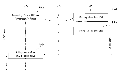
81789720
ACKTimeout interval is determined on the basis of a value of aPHY-RX-START-
Delay set to a
different value according to whether the preamble channel bandwidth type of
the frame is 1MHz
preamble type or greater than or equal to 2MHz preamble type, and wherein a
preamble channel
bandwidth of the response frame is set to a value equal to the preamble
channel bandwidth type of the
frame.
1201 It is to be understood that both the foregoing general description
and the following detailed
description of the present invention are exemplary and explanatory and are
intended to provide further
explanation of the invention as claimed.
[Advantageous Effects]
1211 According to the present invention, resource waste can be prevented
and frame switching can
be correctly performed by providing a method and apparatus for waiting for a
response frame or
deferring channel access in consideration of a response frame type and/or a
channel bandwidth.
1221 It will be appreciated by persons skilled in the art that the
effects that can be achieved with
the present invention are not limited to what has been particularly described
hereinabove and other
advantages of the present invention will be more clearly understood from the
following detailed
description taken in conjunction with the accompanying drawings.
[ Description of Drawings]
1231 The accompanying drawings, which are included to provide a further
understanding of the
invention, illustrate embodiments of the invention and together with the
description serve to explain
the principle of the invention.
1241 FIG. 1 exemplarily shows an IEEE 802.11 system according to one
embodiment of the
present invention.
125] FIG. 2 exemplarily shows an IEEE 802.11 system according to another
embodiment of the
present invention.
3a
CA 2897744 2017-12-21
CA 02897744 2015-07-09
[26] FIG. 3 exemplarily shows an IEEE 802.11 system according to still
another
embodiment of the present invention.
[27] FIG. 4 is a conceptual diagram illustrating a WLAN system.
[28] FIG. 5 is a flowchart illustrating a link setup process for use in the
WLAN system.
[29] FIG. 6 is a conceptual diagram illustrating a backoff procedure.
[30] FIG. 7 is a conceptual diagram illustrating a hidden node and an
exposed node.
[31] FIG. 8 is a conceptual diagram illustrating RTS (Request To Send) and
CTS (Clear To
Send).
[32] FIG. 9 is a diagram for explaining an exemplary frame structure used
in an IEEE 802.11
system.
[33] FIG. 10 is a diagram illustrating an exemplary S1G 1MHz format.
[34] FIG. 11 is a diagram illustrating an exemplary short format of S1G
greater than or equal to
2MHz.
[35] FIG. 12 is a diagram illustrating an exemplary long format of S1G
greater than or equal to
2MHz.
[36] FIG. 13 is a diagram for explaining an ACK procedure.
[37] FIG. 14 is a diagram for explaining whether a frame exchange sequence
is allowed
according to the present invention.
[38] FIG. 15 is a diagram for explaining an example of the present
invention using a response
frame type field of an SIG field of a PLCP header.
[39] FIG. 16 is a diagram for explaining an exemplary method of the present
invention.
[40] FIG. 17 is a block diagram of a wireless apparatus according to an
embodiment of the
present invention.
[Best Mode]
[41] Reference will now be made in detail to the preferred embodiments of
the present
invention, examples of which are illustrated in the accompanying drawings. The
detailed
description, which will be given below with reference to the accompanying
drawings, is
intended to explain exemplary embodiments of the present invention, rather
than to show the
only embodiments that can be implemented according to the present invention.
The
.. following detailed description includes specific details in order to
provide a thorough
understanding of the present invention. However, it will be apparent to those
skilled in the
art that the present invention may be practiced without such specific details.
[42] The following embodiments are proposed by combining constituent
components and
characteristics of the present invention according to a predetermined format.
The individual
constituent components or characteristics should be considered optional
factors on the
4
CA 02897744 2017-02-14
74420-724
condition that there is no additional remark. If required, the individual
constituent
components or characteristics may not be combined with other components or
characteristics.
In addition, some constituent components and/or characteristics may be
combined to
implement the embodiments of the present invention. The order of operations to
be disclosed
in the embodiments of the present invention may be changed. Some components or
characteristics of any embodiment may also be included in other embodiments,
or may be
replaced with those of the other embodiments as necessary.
[43] It should be noted that specific terms disclosed in the present
invention are proposed
for convenience of description and better understanding of the present
invention, and the use
of these specific terms may be changed to other formats. within the technical
scope of
the present invention.
[44] In some instances, well-known structures and devices are omitted in order
to avoid
obscuring the concepts of the present invention and important functions of the
structures and
devices are shown in block diagram form. The same reference numbers will be
used
throughout the drawings to refer to the same or like parts.
[45] Exemplary embodiments of the present invention are supported by standard
documents disclosed for at least one of wireless access systems including an
Institute of
Electrical and Electronics Engineers (IEEE) 802 system, a 31d Generation
Partnership Project '
(3OPP) system, a 3GPP Long Term Evolution (LTE) system, an LTE-Advanced (LIE-
A)
system, and a 3GPP2 system. In particular, steps or parts, which are not
described to clearly
reveal the tft-hnical idea of the present invention, in the embodiments of the
present invention
may be supported by the above documents. All terminology used herein may be
supported
by at least one of the above-mentioned documents.
[46] The following embodiments of the present invention can be applied to a
variety of
wireless access technologies, for example, CDMA (Code Division Multiple Artrti-
cs), FDMA
(Frequency Division Multiple Access), TDMA (Time Division Multiple Access),
OFDMA
(Orthogonal Frequency Division Multiple Access), SC-FDMA (Single Carrier
Frequency
Division Multiple Access), and the like. CDMA may be embodied through wireless
(or radio)
technology such as UTRA (Universal Terrestrial Radio Access) or CDMA2000. TDMA
may be embodied through wireless (or radio) technology such as GSM (Global
System for
Mobile communication)/GPRS (General Packet Radio Service)/EDGE (Enhanced Data
Rates
for GSM Evolution). OFDMA may be embodied through wireless (or radio)
technology
such as Institute of Electrical and Electronics Engineers (IEEE) 802.11 (Wi-
Fi), IEEE 802.16
(WEvfAX), IEEE 802-20, and E-UTRA (Evolved UTRA). For clarity, the following
5
. ,
CA 02897744 2015-07-09
description focuses on IEEE 802.11 systems. However, technical features of the
present
invention are not limited thereto.
[47] WLAN system structure
[48] FIG. 1 exemplarily shows an IEEE 802.11 system according to one
embodiment of
the present invention.
[49] The structure of the IEEE 802.11 system may include a plurality of
components. A
WLAN which supports transparent STA mobility for a higher layer may be
provided by
mutual operations of the components. A Basic Service Set (BSS) may correspond
to a basic
constituent block in an IEEE 802.11 LAN. In FIG. 1, two BSSs (BSS1 and BSS2)
are shown
and two STAs are included in each of the BSSs (i.e. STA1 and STA2 are included
in BSS1
and STA3 and STA4 are included in BSS2). An ellipse indicating the BSS in FIG.
1 may be
understood as a coverage area in which STAs included in the corresponding BS S
maintain
communication. This area may be referred to as a Basic Service Area (BSA). If
an STA
moves out of the BSA, the STA cannot directly communicate with the other STAs
in the
corresponding BSA.
[50] In the IEEE 802.11 LAN, the most basic type of BSS is an Independent
BSS (IBSS).
For example, the IBSS may have a minimum form consisting of only two STAs. The
BSS
(BSS1 or BSS2) of FIG. 1, which is the simplest form and in which other
components are
omitted, may correspond to a typical example of the IBSS. Such configuration
is possible
when STAs can directly communicate with each other. Such a type of LAN is not
prescheduled and may be configured when the LAN is necessary. This may be
referred to as
an ad-hoc network.
[51] Memberships of an STA in the BSS may be dynamically changed when the
STA is
switched on or off or the STA enters or leaves the BSS region. The STA may use
a
synchronization process to join the BSS. To access all services of a BSS
infrastructure, the
STA should be associated with the BSS. Such association may be dynamically
configured
and may include use of a Distribution System Service (DSS).
[52] FIG. 2 is a diagram showing another exemplary structure of an IEEE
802.11 system to
which the present invention is applicable. In FIG. 2, components such as a
Distribution
System (DS), a Distribution System Medium (DSM), and an Access Point (AP) are
added to
the structure of FIG. 1.
[53] A direct STA-to-STA distance in a LAN may be restricted by PHY
performance. In
some cases, such restriction of the distance may be sufficient for
communication. However,
in other cases, communication between STAs over a long distance may be
necessary. The
DS may be configured to support extended coverage.
6
CA 02897744 2015-07-09
[54] The DS refers to a structure in which BSSs are Connected to each
other. Specifically,
a BSS may be configured as a component of an extended form of a network
consisting of a
plurality of BSSs, instead of independent configuration as shown in FIG. 1.
[55] The DS is a logical concept and may be specified by the characteristic
of the DSM.
In relation to this, a Wireless Medium (WM) and the DSM are logically
distinguished in IEEE
802.11. Respective logical media are used for different purposes and are used
by different
components. In definition of IEEE 802.11, such media are not restricted to the
same or
different media. The flexibility of the IEEE 802.11 LAN architecture (DS
architecture or
other network architectures) can be explained in that a plurality of media is
logically different.
That is, the IEEE 802.11 LAN architecture can be variously implemented and may
be
independently specified by a physical characteristic of each implementation.
[56] The DS may support mobile devices by providing seamless integration of
multiple
BSSs and providing logical services necessary for handling an address to a
destination.
[57] The AP refers to an entity that enables associated STAs to access the
DS through a
WM and that has STA functionality. Data may move between the BSS and the DS
through
the AP. For example, STA2 and STA3 shown in FIG. 2 have STA functionality and
provide
a function of causing associated STAs (STA1 and STA4) to access the DS.
Moreover, since
all APs correspond basically to STAs, all APs are addressable entities. An
address used by
an AP for communication on the WM need not always be identical to an address
used by the
AP for communication on the DSM.
[58] Data transmitted from one of STAs associated with the AP to an STA
address of the
AP may always be received by an uncontrolled port and may be processed by an
IEEE 802.1X
port access entity. If the controlled port is authenticated, transmission data
(or frame) may be
transmitted to the DS.
[59] FIG. 3 is a diagram showing still another exemplary structure of an
IEEE 802.11
system to which the present invention is applicable. In addition to the
structure of FIG. 2,
FIG. 3 conceptually shows an Extended Service Set (ESS) for providing wide
coverage.
[60] A wireless network having arbitrary size and complexity may be
comprised of a DS
and BSSs. In the IEEE 802.11 system, such a type of network is referred to an
ESS network.
The ESS may correspond to a set of BSSs connected to one DS. However, the ESS
does not
include the DS. The ESS network is characterized in that the ESS network
appears as an
IBSS network in a Logical Link Control (LLC) layer. STAs included in the ESS
may
communicate with each other and mobile STAs are movable transparently in LLC
from one
BSS to another BSS (within the same ESS).
7
CA 02897744 2015-07-09
[61] In IEEE 802.11, relative physical locations of the BSSs in FIG. 3 are
not assumed and
the following forms are all possible. BSSs may partially overlap and this form
is generally
used to provide continuous coverage. BSSs may not be physically connected and
the logical
distances between BSSs have no limit. BSSs may be located at the same physical
position
and this form may be used to provide redundancy. One or more IBSSs or ESS
networks may
be physically located in the same space as one or more ESS networks. This may
correspond
to an ESS network form in the case in which an ad-hoc network operates in a
location in
which an ESS network is present, the case in which IEEE 802.11 networks of
different
organizations physically overlap, or the case in which two or more different
access and
security policies are necessary in the same location.
[62] FIG. 4 is a diagram showing an exemplary structure of a WLAN system.
In FIG. 4,
an example of an infrastructure BSS including a DS is shown.
[63] In the example of FIG. 4, BSS1 and BSS2 constitute an ESS. In the WLAN
system,
an STA is a device operating according to MAC/PHY regulation of IEEE 802.11.
STAs
include AP STAs and non-AP STAs. The non-AP STAs correspond to devices, such
as
laptop computers or mobile phones, handled directly by users. In FIG. 4, STA1,
STA3, and
STA4 correspond to the non-AP STAs and STA2 and STA5 correspond to AP STAs.
[64] In the following description, the non-AP STA may be referred to as a
terminal, a
Wireless Transmit/Receive Unit (WTRU), a User Equipment (UE), a Mobile Station
(MS), a
mobile terminal, or a Mobile Subscriber Station (MSS). The AP is a concept
corresponding
to a Base Station (BS), a Node-B, an evolved Node-B (e-NB), a Base Transceiver
System
(BTS), or a femto BS in other wireless communication fields.
[65] Layer Structure
[66] In the WLAN system, an operation of an AP and/or STA in the present
invention may
.. be described from the perspective of a layer structure. The layer structure
in terms of device
configuration may be implemented by a processor. The AP or the STA may have a
plurality
of layer structures. For example, the 802.11 standard specifications mainly
deal with a
Medium Access Control (MAC) sublayer of a Data Link Layer (DLL) and a Physical
(PRY)
layer. The PHY layer may include a Physical Layer Convergence Protocol (PLCP)
entity
and a Physical Medium Dependent (PMD) entity. The MAC sublayer and the PHY
layer
conceptually include management entities, called a MAC Sublayer Management
Entity
(MLME) and a PHY Layer Management Entity (PLIVILE), respectively. These
entities
provide layer management service interfaces through which layer management
functions may
be invoked.
8
CA 02897744 2015-07-09
[67] In order to provide a correct MAC operation, a Station Management
Entity (SME) is
present within each of the AP and STA. The SME is a layer-independent entity
that may be
viewed as residing in a separate management plane or as residing off to the
side. The exact
functions of the SME are not described in detail but, in general, this entity
may be viewed as
being responsible for such functions as gathering of information about layer-
dependent
statuses from various Layer Management Entities (LMEs) and similarly setting
the values of
layer-specific parameters. The SME may typically perform such functions on
behalf of
general system management entities and may implement standard management
protocols.
[68] The foregoing entities interact in various ways. For example, the
entities may
interact with each other by exchanging GET/SET primitives. An XX-GET.request
primitive
is used to request the value of a given MIB attribute (management information-
based attribute
information). An XX-GET.confirm primitive returns an appropriate M113
attribute value if
Status = "success" and otherwise, returns an error indication in a status
field. An XX-
SET.request primitive is used to request that an indicated MIB attribute be
set to a given value.
If the MIB attribute implies a specific action, then this requests that the
action be performed.
An XX-SET.confirm primitive confirms that an indicated MIB attribute has been
set to a
requested value, if Status = "success," and otherwise, the XX-SET.comfirm
primitive returns
an error condition in the status field. If the MIB attribute implies a
specific action, then this
confirms that the action has been performed.
[69] The MLME and the SME may exchange various MLME_GET/SET primitives via an
MLME SAP (Service Access Point). In addition, various PLME_GET/SET primitives
may
be exchanged between the PLME and the SME via a PLME_SAP and between the MLME
and the PLME via an MLME-PLME SAP.
[70] Link Setup Process
171] FIG. 5 is a flowchart explaining a general link setup process
according to an
exemplary embodiment of the present invention.
1721 In order to allow an STA to establish link setup on the network as
well as to
transmit/receive data over the network, the STA must perform such link setup
through
processes of network discovery, authentication, and association, and must
establish association
and perform security authentication. The link setup process may also be
referred to as a
session initiation process or a session setup process. In addition, an
association step is a
generic term for discovery, authentication, association, and security setup
steps of the link
setup process.
[73] Link setup process is described referring to Fig. 5.
9
CA 02897744 2015-07-09
[74] In step S510, STA may perform the network discovery action. The
network
discovery action may include the STA scanning action. That is, STA must search
for an
available network so as to access the network. The STA must identify a
compatible network
before participating in a wireless network. Here, the process for identifying
the network
contained in a specific region is referred to as a scanning process.
1751 The scanning scheme is classified into active scanning and passive
scanning.
1761 FIG. 5 is a flowchart illustrating a network discovery action
including an active
scanning process. In the case of the active scanning, an STA configured to
perform scanning
transmits a probe request frame and waits for a response to the probe request
frame, such that
the STA can move between channels and at the same time can determine which AP
(Access
Point) is present in a peripheral region. A responder transmits a probe
response frame, acting
as a response to the probe request frame, to the STA having transmitted the
probe request
frame. In this case, the responder may be an STA that has finally transmitted
a beacon frame
in a BSS of the scanned channel. In BSS, since the AP transmits the beacon
frame, the AP
operates as a responder. In IBSS, since STAs of the IBSS sequentially transmit
the beacon
frame, the responder is not constant. For example, the STA, that has
transmitted the probe
request frame at Channel #1 and has received the probe response frame at
Channel #1, stores
BSS-associated information contained in the received probe response frame, and
moves to the
next channel (for example, Channel #2), such that the STA may perform scanning
using the
same method (i.e., probe request/response transmission/reception at Channel
#2).
[77] Although not shown in FIG. 5, the scanning action may also be
carried out using
passive scanning. An STA configured to perform scanning in the passive
scanning mode
waits for a beacon frame while simultaneously moving from one channel to
another channel.
The beacon frame is one of management frames in IEEE 802.11, indicates the
presence of a
wireless network, enables the STA performing scanning to search for the
wireless network,
and is periodically transmitted in a manner that the STA can participate in
the wireless
network. In BSS, the AP is configured to periodically transmit the beacon
frame. In IBSS,
STAs of the IBSS are configured to sequentially transmit the beacon frame. If
each STA for
scanning receives the beacon frame, the STA stores BSS information contained
in the beacon
frame, and moves to another channel and records beacon frame information at
each channel.
The STA having received the beacon frame stores BSS-associated information
contained in
the received beacon frame, moves to the next channel, and thus performs
scanning using the
same method.
CA 02897744 2015-07-09
[78] In comparison between the active scanning and the passive scanning,
the active
scanning is more advantageous than the passive scanning in terms of delay and
power
consumption.
[79] After the STA discovers the network, the STA may perform the
authentication
.. process in step S520. The authentication process may be referred to as a
first authentication
process in such a manner that the authentication process can be clearly
distinguished from the
security setup process of step S540.
[80] The authentication process may include transmitting an authentication
request frame
to an AP by the STA, and transmitting an authentication response frame to the
STA by the AP
in response to the authentication request frame. The authentication frame used
for
authentication request/response may correspond to a management frame.
[81] The authentication frame may include an authentication algorithm
number, an
authentication transaction sequence number, a state code, a challenge text, a
Robust Security
Network (RSN), a Finite Cyclic Group (FCG). etc. The above-mentioned
information
contained in the authentication frame may correspond to some parts of
information capable of
being contained in the authentication request/response frame, may be replaced
with other
information, or may include additional information.
[82] The STA may transmit the authentication request frame to the AP. The
AP may
decide whether to authenticate the corresponding STA on the basis of
information contained in
the received authentication request frame. The AP may provide the
authentication result to
the STA through the authentication response frame.
[83] After the STA has been successfully authenticated, the association
process may be
carried out in step S530. The association process may involve transmitting an
association
request frame to the AP by the STA, and transmitting an association response
frame to the
STA by the AP in response to the association request frame.
[84] For example, the association request frame may include information
associated with
various capabilities, a beacon listen interval, a Service Set Identifier
(SSID), supported rates,
supported channels, RSN, mobility domain, supported operating classes, a TIM
(Traffic
Indication Map) broadcast request, interworking service capability, etc.
[85] For example, the association response frame may include information
associated with
various capabilities, a state code, an Association ID (AID), supported rates,
an Enhanced
Distributed Channel Access (EDCA) parameter set, a Received Channel Power
Indicator
(RCPI), a Received Signal to Noise Indicator (RSNI), mobility domain, a
timeout interval
(association comeback time), an overlapping BSS scan parameter, a TIM
broadcast response,
a QoS map, etc.
11
CA 02897744 2015-07-09
[86] The above-mentioned information may' correspond to some parts of
information
capable of being contained in the association request/response frame, may be
replaced with
other information, or may include additional information.
[87] After the STA has been successfully associated with the network, a
security setup
.. process may be carried out in step S540. The security setup process of Step
S540 may be
referred to as an authentication process based on Robust Security Network
Association
(RSNA) request/response. The authentication process of step S520 may be
referred to as a
first authentication process, and the security setup process of Step S540 may
also be simply
referred to as an authentication process.
[88] For example, the security setup process of Step S540 may include a
private key setup
process through 4-way handshaking based on an (Extensible Authentication
Protocol over
LAN (EAPOL) frame. In addition, the security setup process may also be carried
out
according to other security schemes not defined in IEEE 802.11 standards.
[89] WLAN Evolution
[90] In order to obviate limitations in WLAN communication speed, IEEE
802.11n has
recently been established as a communication standard. IEEE 802.11n aims to
increase
network speed and reliability as well as to extend a coverage region of the
wireless network.
In more detail, IEEE 802.11n supports a High Throughput (HT) of a maximum of
540Mbps,
and is based on MIMO technology in which multiple antennas are mounted to each
of a
transmitter and a receiver.
[91] With the widespread use of WLAN technology and diversification of WLAN
applications, there is a need to develop a new WLAN system capable of
supporting a HT
higher than a data processing speed supported by IEEE 802.11n. The next
generation
WLAN system for supporting Very High Throughput (VHT) is the next version (for
example,
IEEE 802.1 lac) of the IEEE 802.11n WLAN system, and is one of IEEE 802.11
WLAN
systems recently proposed to support a data process speed of 1Gbps or more at
a MAC SAP
(Medium Access Control Service Access Point).
[92] In order to efficiently utilize a radio frequency (RF) channel, the
next generation
WLAN system supports MU-MIMO (Multi User Multiple Input Multiple Output)
transmission in which a plurality of STAs can simultaneously access a channel.
In
accordance with the MU-MIMO transmission scheme, the AP may simultaneously
transmit
packets to at least one MIMO-paired STA.
[93] In addition, a technology for supporting WLAN system operations in
whitespace has
recently been discussed. For example, a technology for introducing the WLAN
system in
whitespace (TV WS) such as an idle frequency band (for example, 54-698MHz
band) left
12
CA 02897744 2015-07-09
because of the transition to digital TV has been discussed under the IEEE
802.11af standard.
However, the above-mentioned information is disclosed for illustrative
purposes only, and the
whitespace may be a licensed band capable of being primarily used only by a
licensed user.
The licensed user may be a user who has authority to use the licensed band,
and may also be
referred to as a licensed device, a primary user, an incumbent user, or the
like.
[94] For example, an AP and/or STA operating in the whitespace (WS) must
provide a
function for protecting the licensed user. For example, assuming that the
licensed user such
as a microphone has already used a specific WS channel acting as a divided
frequency band on
regulation in a manner that a specific bandwidth is occupied from the WS band,
the AP and/or
STA cannot use the frequency band corresponding to the corresponding WS
channel so as to
protect the licensed user. In addition, the AP and/or STA must stop using the
corresponding
frequency band under the condition that the licensed user uses a frequency
band used for
transmission and/or reception of a current frame.
[95] Therefore, the AP and/or STA must determine whether to use a specific
frequency
band of the WS band. In other words, the AP and/or STA must determine the
presence or
absence of an incumbent user or a licensed user in the frequency band. The
scheme for
determining the presence or absence of the incumbent user in a specific
frequency band is
referred to as a spectrum sensing scheme. An energy detection scheme, a
signature detection
scheme and the like may be used as the spectrum sensing mechanism. The AP
and/or STA
may determine that the frequency band is being used by an incumbent user if
the intensity of a
received signal exceeds a predetermined value, or when a DTV preamble is
detected.
[96] M2M (Machine to Machine) communication technology has been discussed
as next
generation communication technology.
Technical standard for supporting M2M
communication has been developed as IEEE 802.11ah in the IEEE 802.11 WLAN
system.
M2M communication refers to a communication scheme including one or more
machines, or
may also be referred to as Machine Type Communication (MTC) or Machine To
Machine
(M2M) communication. In this case, the machine may be an entity that does not
require
direct handling and intervention of a user. For example, not only a meter or
vending machine
including a RF module, but also a user equipment (UE) (such as a smartphone)
capable of
performing communication by automatically accessing the network without user
intervention/handling may be an example of such machines. M2M communication
may
include Device-to-Device (D2D) communication and communication between a
device and an
application server, etc. As exemplary communication between the device and the
application
server, communication between a vending machine and an application server,
communication
between the Point of Sale (POS) device and the application server, and
communication
13
CA 02897744 2015-07-09
between an electric meter, a gas meter or a water meter and the application
server. M2M-
based communication applications may include security, transportation,
healthcare, etc. In
the case of considering the above-mentioned application examples, M2M
communication has
to support the method for sometimes transmitting/receiving a small amount of
data at low
.. speed under an environment including a large number of devices.
[97] In more detail, M2M communication must support a large number of STAs.
Although the current WLAN system assumes that one AP is associated with a
maximum of
2007 STAs, various methods for supporting other cases in which many more STAs
(e.g., about
6000 STAs) are associated with one AP have recently been discussed in M2M
communication.
.. In addition, it is expected that many applications for
supporting/requesting a low transfer rate
are present in M2M communication. In order to smoothly support many STAs, the
WLAN
system may recognize the presence or absence of data to be transmitted to the
STA on the
basis of a TIM (Traffic Indication map), and various methods for reducing the
bitmap size of
the TIM have recently been discussed. In addition, it is expected that much
traffic data
.. having a very long transmission/reception interval is present in M2M
communication. For
example, in M2M communication, a very small amount of data (e.g.,
electric/gas/water
metering) needs to be transmitted at long intervals (for example, every
month). Therefore,
although the number of STAs associated with one AP increases in the WLAN
system, many
developers and companies are conducting intensive research into an WLAN system
which can
efficiently support the case in which there are a very small number of STAs,
each of which has
a data frame to be received from the AP during one beacon period.
[98] As described above, WLAN technology is rapidly developing, and not
only the above-
mentioned exemplary technologies but also other technologies such as a direct
link setup,
improvement of media streaming throughput, high-speed and/or support of large-
scale initial
session setup, and support of extended bandwidth and operation frequency, are
being
intensively developed.
[99] Medium Access Mechanism
[100] In the IEEE 802.11 ¨ based WLAN system, a basic access mechanism of MAC
(Medium Access Control) is a Carrier Sense Multiple Access with Collision
Avoidance
(CSMA/CA) mechanism. The CSMA/CA mechanism is referred to as a Distributed
Coordination Function (DCF) of IEEE 802.11 MAC, and basically includes a
"Listen Before
Talk" access mechanism. In accordance with the above-mentioned access
mechanism, the
AP and/or STA may perform Clear Channel Assessment (CCA) for sensing an RF
channel or
medium during a predetermined time interval (for example, DCF Inter-Frame
Space (DIES)).
.. prior to data transmission. If it is determined that the medium is in the
idle state, frame
14
CA 02897744 2015-07-09
transmission through the corresponding medium begins. On the other hand, if it
is
determined that the medium is in the occupied state, the corresponding AP
and/or STA does
not start its own transmission, establishes a delay time (for example, a
random backoff period)
for medium access, and attempts to start frame transmission after waiting for
a predetermined
time. Through application of a random backoff period, it is expected that
multiple STAs will
attempt to start frame transmission after waiting for different times,
resulting in minimum
collision.
[101] In addition. IEEE 802.11 MAC protocol provides a Hybrid Coordination
Function
(HCF). HCF is based on DCF and Point Coordination Function (PCF). PCF refers
to the
polling-based synchronous access scheme in which periodic polling is executed
in a manner
that all reception (Rx) APs and/or STAs can receive the data frame. In
addition, HCF
includes Enhanced Distributed Channel Access (EDCA) and HCF Controlled Channel
Access
(HCCA). EDCA is achieved when the access scheme provided from a provider to a
plurality
of users is contention-based. HCCA is achieved by the contention-free-based
channel access
scheme based on the polling mechanism. In addition, HCF includes a medium
access
mechanism for improving Quality of Service (QoS) of WLAN, and may transmit QoS
data in
both a Contention Period (CP) and a Contention Free Period (CFP).
[102] FIG. 6 is a conceptual diagram illustrating a backoff procedure.
1103] Operations based on a random backoff period will hereinafter be
described with
reference to FIG. 6. If the occupy- or busy- state medium is shifted to an
idle state, several
STAs may attempt to transmit data (or frame). As a method for implementing a
minimum
number of collisions, each STA selects a random backoff count, waits for a
slot time
corresponding to the selected backoff count, and then attempts to start data
transmission.
The random backoff count is a pseudo-random integer, and may be set to one of
0 to CW
values. In this case, CW refers to a Contention Window parameter value.
Although an
initial value of the CW parameter is denoted by CWmin, the initial value may
be doubled in
case of a transmission failure (for example, in the case in which ACK of the
transmission
frame is not received). If the CW parameter value is denoted by CWmax, CWmax
is
maintained until data transmission is successful, and at the same time it is
possible to attempt
to start data transmission. If data transmission was successful, the CW
parameter value is
reset to CWmin. Preferably, CW, CWmin, and CWmax are set to 2n-1 (where n=0,
1, 2. ...).
[104] If the random backoff procedure starts operation, the STA continuously
monitors the
medium while counting down the backoff slot in response to the decided backoff
count value.
If the medium is monitored as the occupied state, the countdown stops and
waits for a
predetermined time. If the medium is in the idle state, the remaining
countdown restarts.
CA 02897744 2015-07-09
[105] As shown in the example of FIG. 6, if 'a packet to be transmitted to MAC
of STA3
arrives at the STA3, the STA3 determines whether the medium is in the idle
state during the
DIFS, and may directly start frame transmission. In the meantime, the
remaining STAs
monitor whether the medium is in the busy state, and wait for a predetermined
time. During
.. the predetermined time, data to be transmitted may occur in each of STA1,
STA2, and STA5.
If the medium is in the idle state, each STA waits for the DIFS time and then
performs
countdown of the backoff slot in response to a random backoff count value
selected by each
STA. The example of FIG. 6 shows that STA2 selects the lowest backoff count
value and
STA1 selects the highest backoff count value. That is, after STA2 finishes
backoff counting,
the residual backoff time of STA5 at a frame transmission start time is
shorter than the
residual backoff time of STA1. Each of STA1 and STA5 temporarily stops
countdown while
STA2 occupies the medium, and waits for a predetermined time. If occupying of
the STA2
is finished and the medium re-enters the idle state, each of STA1 and STA5
waits for a
predetermined time DIPS, and restarts backoff counting. That is, after the
remaining backoff
.. slot as long as the residual backoff time is counted down, frame
transmission may start
operation. Since the residual backoff time of STA5 is shorter than that of
STA1, STA5 starts
frame transmission. Meanwhile, data to be transmitted may occur in STA4 while
STA2
occupies the medium. In this case, if the medium is in the idle state, STA4
waits for the
DIFS time, performs countdown in response to the random backoff count value
selected by the
.. STA4, and then starts frame transmission. FIG. 6 exemplarily shows the case
in which the
residual backoff time of STA5 is identical to the random backoff count value
of STA4 by
chance. In this case, an unexpected collision may occur between STA4 and STA5.
If the
collision occurs between STA4 and STA5, each of STA4 and STA5 does not receive
ACK,
resulting in the occurrence of a failure in data transmission. In this case,
each of STA4 and
SIAS increases the CW value two times, and STA4 or STA5 may select a random
backoff
count value and then perform countdown. Meanwhile, STA1 waits for a
predetermined time
while the medium is in the occupied state due to transmission of STA4 and
STA5. In this
case, if the medium is in the idle state, STA1 waits for the DIFS time, and
then starts frame
transmission after lapse of the residual backoff time.
.. [106] STA Sensing Operation
[107] As described above, the CSMA/CA mechanism includes not only a physical
carrier
sensing mechanism in which the AP and/or STA can directly sense the medium,
but also a
virtual carrier sensing mechanism. The virtual carrier sensing mechanism can
solve some
problems (such as a hidden node problem) encountered in the medium access. For
the virtual
carrier sensing, MAC of the WLAN system can utilize a Network Allocation
Vector (NAV).
16
CA 02897744 2015-07-09
In more detail, by means of the NAV value, the AP and/or STA, each of which
currently uses
the medium or has authority to use the medium, may inform another AP and/or
another STA
for the remaining time in which the medium is available. Accordingly, the NAV
value may
correspond to a reserved time in which the medium will be used by the AP
and/or STA
configured to transmit the corresponding frame. An STA having received the NAV
value
may prohibit medium access (or channel access) during the corresponding
reserved time. For
example, NAV may be set according to the value of a 'duration' field of the
MAC header of
the frame.
[108] The robust collision detect mechanism has been proposed to reduce the
probability of
such collision, and as such a detailed description thereof will hereinafter be
described with
reference to FIGS. 7 and 8. Although an actual carrier sensing range is
different from a
transmission range, it is assumed that the actual carrier sensing range is
identical to the
transmission range for convenience of description and better understanding of
the present
invention.
1109] FIG. 7 is a conceptual diagram illustrating a hidden node and an exposed
node.
[110] FIG. 7(a) exemplarily shows the hidden node. In FIG. 7(a), STA A
communicates
with STA B, and STA C has information to be transmitted. In FIG. 7(a), STA C
may
determine that the medium is in the idle state when performing carrier sensing
before
transmitting data to STA B, under the condition that STA A transmits
information to STA B.
Since transmission of STA A (i.e., occupied medium) may not be detected at the
location of
STA C, it is determined that the medium is in the idle state. In this case,
STA B
simultaneously receives information of STA A and information of STA C,
resulting in the
occurrence of collision. here, STA A may be considered as a hidden node of STA
C.
[111] FIG. 7(b) exemplarily shows an exposed node. In FIG. 7(b), under the
condition that
STA B transmits data to STA A, STA C has information to be transmitted to STA
D. If STA
C performs carrier sensing, it is determined that the medium is occupied due
to transmission of
STA B. Therefore, although STA C has information to be transmitted to STA D,
the
medium-occupied state is sensed, such that the STA C must wait for a
predetermined time (i.e.,
standby mode) until the medium is in the idle state. However, since STA A is
actually
located out of the transmission range of STA C, transmission from STA C may
not collide
with transmission from STA B from the viewpoint of STA A, such that STA C
unnecessarily
enters the standby mode until STA B stops transmission. Here. STA C is
referred to as an
exposed node of STA B.
[112] FIG. 8 is a conceptual diagram illustrating RTS (Request To Send) and
CTS (Clear To
Send).
17
CA 02897744 2015-07-09
[113] In order to efficiently utilize the collision avoidance mechanism under
the above-
mentioned situation of FIG. 7, it is possible to use a short signaling packet
such as RTS
(request to send) and CTS (clear to send). RTS/CTS between two STAs may be
overheared
by peripheral STA(s), such that the peripheral STA(s) may consider whether
information is
communicated between the two STAs. For example, if STA to be used for data
transmission
transmits the RTS frame to the STA having received data, the STA having
received data
transmits the CTS frame to peripheral STAs, and may inform the peripheral STAs
that the
STA is going to receive data.
[114] FIG. 8(a) exemplarily shows the method for solving problems of the
hidden node. In
FIG. 8(a), it is assumed that each of STA A and STA C is ready to transmit
data to STA B.
If STA A transmits RTS to STA B, STA B transmits CTS to each of STA A and STA
C
located in the vicinity of the STA B. As a result, STA C must wait for a
predetermined time
until STA A and STA B stop data transmission, such that collision is prevented
from occurring.
[115] FIG. 8(b) exemplarily shows the method for solving problems of the
exposed node.
STA C performs overhearing of RTS/CTS transmission between STA A and STA B,
such that
STA C may determine no collision although it transmits data to another STA
(for example,
STA D). That is, STA B transmits an RTS to all peripheral STAs, and only STA A
having
data to be actually transmitted can transmit a CTS. STA C receives only the
RTS and does
not receive the CTS of STA A, such that it can be recognized that STA A is
located outside of
the carrier sensing range of STA C.
[116] Frame Structure
[117] FIG. 9 is a diagram for explaining an exemplary frame structure used in
an IEEE 802.11
system.
[118] A Physical Layer Convergence Protocol (PLCP) Packet Data Unit (PPDU)
frame format
may include a Short Training Field (STF), a Long Training Field (LTF), a
Signal (SIG) field, and
a data (DATA) field. The most fundamental (e.g. non-High Throughput (HT)) PPDU
frame
format may include only a Legacy-STF (L-STF), a Legacy-LTF (L-LTF), a SIG
field, and a
DATA field. Additional (or another type of) STF, LTF, and SIG field may be
included
between the SIG field and the DATA field according to a PPDU frame format type
(e.g. HT-
mixed format PPDU, HT-greenfield format PPDU, Very High Throughput (VHT) PPDU,
etc.).
[119] The STF is a field for signals for signal detection, Automatic Gain
Control (AGC),
diversity selection, accurate time synchronization, etc. The LTF is a field
for signals for
channel estimation, frequency error estimation, etc. Both the STF and the LTF
may be
referred to as a PCLP preamble. The PI,CP preamble may be a signal for
synchronization of
an OFDM physical layer and channel estimation.
18
CA 02897744 2015-07-09
11201 The SIG field may include a Rate field and a Length field. The Rate
field may
include information about data modulation and coding rate. The Length field
may include
information about the length of data. Additionally, the SIG field may include
a parity bit, a
SIG tail bit, etc.
[121] The DATA field may include a Service field, a PLCP Service Data Unit
(PSDU), and
a PPDU tail bit and may further include a padding (PAD) bit when necessary.
Some bits of
the Service field may be used for synchronization of a descrambler in a
receiver. The PSDU
may correspond to a MAC Packet Data Unit (PDU) defined in a MAC layer and
include data
generated/used in a higher layer. The PPDU tail bit may be used to return an
encoder to the
state of, O. The PAD bit may be used to adjust the length of the data field to
a predetermined
unit.
[122] A MAC header includes a Frame Control field, a Duration/ID field, an
Address field,
etc. The Frame Control field may include control information necessary for
frame
transmission/reception. The Duration/ID field may be set to a time for
transmitting a
corresponding frame. For a detailed description of Sequence Control, QoS
Control. and HT
Control subfields of the MAC header, refer to the IEEE 802.11-1012 standard
specification.
[123] The Frame Control field of the MAC header may include Protocol Version
Type,
Subtype, To DS, From DS, More Fragment, Retry, Power Management, More Data,
and
Protected Frame Order subfields. For a description of the Frame Control Field
and subfields
.. of the Frame Control field, refer to the IEEE 802.11-1012 standard
specification.
[124] Meanwhile, a Null-Data Packet (NDP) frame format refers to a frame
format which
does not include a data packet. That is, the NDP frame includes only a PI,CP
header (i.e. an
STF, an LTF, and a SIG field) in a non-nal PPDU format and does not include
the other part
(i.e. a data field). The NDP frame may also be referred to as a short frame
format.
[125] SKI Frame Format
1126] In order to support applications such as M2M, Internet of Things (IoT),
smart grid, etc.,
long-range, low-power communication is required. To this end, a communication
protocol
using a channel bandwidth of 1 IVIHz/2M11z/4MHz/8MHz/16MHz in a frequency band
of 1GHz
or below (Sub 1GHz: SIG) (e.g. 902 to 928MHz) is under discussion.
11271 Three types of formats are defined for an SIG PPDU: a short format used
in a
bandwidth of S1G greater than or equal to 2MHz, a long format used in a
bandwidth of SIG
greater than or equal to 2MHz, and a format used in a bandwidth of S1G 1MHz.
[128] FIG. 10 is a diagram illustrating an exemplary SIG 1MHz format.
11291 The S1G 1MHz format may be used for 1MHz PPDU Single User (SU)
transmission.
19
CA 02897744 2015-07-09
[130] Like a Green-field format defined by IEEE 802.11n, the S1G 1MHz format
illustrated in
FIG. 10 includes STF, LTF1, SIG, LTF2-LTFNLTF, and Data fields. However, the
transmission
time of a preamble part of the S1G 1MHz format is increased by two or more
times through
repetition, compared to the Green-field format.
[131] Although the STF field of FIG. 10 has the same periodicity as an STF (a
2-symbol
length) of a PPDU in a bandwidth of 2MHz or above, the STF field is twice
repeated (rep2) in
time and thus has a 4-symbol length (e.g. 160p.$). 3-dB power boosting may be
applied.
[132] The LTF1 field of FIG. 10 is designed to be orthogonal to the LTF1 field
(having a 2-
symbol length) of the PPDU in the bandwidth of 2MHz or above in the frequency
domain and
may be repeated twice in time to have a 4-symbol length. The LTF1 field may
include Double
Guard Interval (DGI), Long Training Sequence (LTS), LTS, Guard Interval (GI),
LTS, GI, and
LTS subfields.
[133] The SIG field of FIG. 15 may be repeatedly encoded. The lowest
Modulation and
Coding Scheme (MCS) (i.e. Binary Phase Shift Keying (BPSK)) and repetition
coding (rep2)
may be applied to the SIG field. The SIG field may be configured to have a
rate of 1/2 and
defined as a length of 6 symbols.
[134] The LTF2 to LTFNL1F fields of FIG. 10 may be included in the case of
MIMO. Each
LTF field may bc one symbol long.
[135] In the 1MHz PPDU preamble format of FIG. 10, the STF, L __________ 1E1,
SIG, and LTF2-LTFNurF
fields correspond to an omni portion transmitted in every direction and are
transmitted without
beamforming so that all STAs may receive the fields.
[136] FIG. 11 illustrates an exemplary short format of S1G greater than or
equal to 2MHz.
[137] The short format of SIG greater than or equal to 2MHz may be used for SU
transmission in
a PPDU of 2MHz, 4MHz, 8MHz, or 16MHz.
[138] The STF field of FIG. 11 may have a length of 2 symbols.
11391 An LTF1 field of FIG. 11 may have a length of 2 symbols and include DGI,
LTS, and LTS.
[140] An SIG field of FIG. 11 may be subjected to Quadrature PSK (QPSK), BPSK,
etc. as an
MCS.
[141] Each of LTF2 to LTFNLTF fields of FIG. 11 may have a length of one
symbol.
[142] FIG. 12 illustrates an exemplary long format of S1G greater than or
equal to 2M1-Iz.
[143] The long format of SIG greater than or equal to 2MHz may be used for MU
transmission
and SU beamformed transmission in a PPDU of 2MHz, 4MHz. 8MHz, or 16MHz. The
long
format of S1G greater than or equal to 2MHz may include an omni portion
transmitted in
omnidireetions so that all STAs may receive the format and a data portion
subjected to beamforming
.. so that specific STAs may receive the format.
CA 02897744 2015-07-09
[144] In the long format of SIG greater than or equal to 2MHz, the omrti
portion may include STF,
LTF1, and Signal-A (SIG-A) fields.
[145] The STF field of FIG. 12 may have a length of 2 symbols.
[146] The LTF1 field of FIG. 12 may have a length of 2 symbols and include
DGI, LTS, and LTS.
[147] The SIG-A field of FIG. 12 may be subjected to QPSK, BPSK, etc. as an
MCS and have a
length of 2 symbols.
[148] In the long format of SIG greater than or equal to 2MHz, the data
portion may include Short
Training Field for Data (D-STF), Long Training Field for Data (STF-L). Signal-
B (SIG-B), and Data
fields. The data portion in the PPDU format of FIG. 12 may be referred to as
an MU portion. In
this sense, D-STF may be referred to as MU-STF and D-LTF may be referred to as
MU-LTF.
[149] The D-STF field of FIG. 12 may have a length of one symbol.
[150] Each subfield of the D-LTF field of FIG. 12, i.e. each of D-LTF1 to D-
LTFNLTF may have a
length of one symbol.
[151] The SIG-B field of FIG. 12 may have a length of one symbol.
.. 1152] Each field of the preamble format of the PPDU of SIG greater than or
equal to 2MHz as
described above will now be described in more detail.
[153] In the omni portion, the STF, LTF1, SIG-A fields may be transmitted as a
single stream
with respect to the respective subcarriers. This may be indicated as follows.
[154] [Equation 1]
[Xk iN 20 xl [Qk ]N dk
[155] In Equation 1, k denotes a subcarrier (or tone) index, xk denotes a
signal transmitted in
subcarrier k, and ND{ denotes the number of transmit antennas. Qk denotes a
column vector for
encoding (e.g. spatial-mapping) a signal transmitted in subcarrier k and dk
indicates data input to an
encoder. In Equation 1, a Cyclic Shift Delay (CSD) in the time domain may be
applied to Qk. The
CSD in the time domain indicates phase rotation or phase shift in the
frequency domain.
Accordingly, Qk may include a phase shift value in tone k generated by the CSD
in the time domain.
[156] When the frame format as illustrated in FIG. 12 is used, the S ___ IF,
LTF1, SIG-A fields may
be received by all STAs and each of the STAs may decode the SIG-A field
through channel
estimation based on the STF and LTF1 fields.
[157] The SIG-A field may include information about length/duration, channel
bandwidth,
number of spatial streams, etc. The SIG-A field has a length of two OFDM
symbols. One OFDM
symbol uses BPSK modulation with respect to 48 data tones and therefore 24
bits of information
may be carried on one OFDM symbol. Then, the SIG-A field may include 48-bit
information.
21
CA 02897744 2015-07-09
[158] The following Table 1 shows exemplary bit assignment of the SIG-A field
for each of an SU
frame and an MU frame.
[159] [Table 1]
Su MU
SU/mu Indication 1 1
Length / Duration 9 9
MCS 4
BW 2 2
Aggregation 1
STBC 1 1
Coding 2 5
SGI 1 1
GID 6
Nsts 2
PAID 9
ACK Indication 2 2
Reserved 3 3
CRC 4 4
Tail 6 6
Total 48 48
[160] In Table 1, the SU/MU Indication field is used to distinguish between an
SU frame format
and an MU frame format.
[161] The Length/Duration field indicates the number of OFDM symbols (i.e.
duration) or the
number of bytes (i.e. length) of a frame. In the SU frame, when the value of
the Aggregation field
is 1, the Length/Duration field is interpreted as the Duration field.
Meanwhile, when the value of
the Aggregation field is 0, the Length/Duration field is interpreted as the
Length field. In the MU
frame, since the Aggregation field is not defined and the MU frame is
configured to always apply
aggregation, the Length/Duration field is interpreted as the Duration field.
[162] The MCS field indicates an MCS used for PSDU transmission. The MCS field
is
transmitted through the SIG-A field only in the SU frame. If other STAs (i.e.
third party STAs (also
called third STAs) that are not directly associated with
transmission/reception between two STAs)
receive the SU frame, the duration of a currently received SU frame (i.e. an
SU beamformed frame in
which the Aggregation field is set to 0) may be calculated based on the length
value of the
Length/Duration field and the value of the MCS field. Meanwhile, the MCS field
of the MU frame
is included not in the SIG-A field but in an SIG-B field carrying user-
specific information and an
MCS may be independently applied to each user.
22
CA 02897744 2015-07-09
[163] The BW field indicates the channel bandwidth of a transmitted SU frame
or MU frame.
For example, the BW field may be set to a value indicating one of 2MHz, 4IVA-
lz, 8MElz, 16MHz,
and 8+8MHz.
[164] The Aggregation field indicates whether PSDUs are aggregated in =the
form of an
Aggregation MAC PDU (i.e. an A-MPDU). If the Aggregation field is set to 1,
this indicates that
the PSDUs are aggregated in the form of the A-MPDU and transmitted. If the
Aggregation field is
set to 0, this represents that the PSDUs are transmitted without being
aggregated. In the MU frame,
since the PSDUs are always transmitted in the form of the A-MPDU, the
Aggregation field does not
need to be signaled and therefore the Aggregation field is not included in the
S1G-A field.
[165] The Space-Time Block Coding (STBC) field indicates whether STBC is
applied to the SU
frame or the MU frame.
[166] The Coding field indicates a coding scheme used for the SU frame or the
MU frame. A
Binary Convolutional Code (BCC) or Low Density Parity Check (LDPC) scheme may
be used for
the SU frame. In the MU frame, an independent coding scheme per user may be
applied and, to
support this scheme, the Coding field may be defined by a size of 2 bits or
more.
[167] The Short Guard Interval (SGI) field indicates whether an SGI is used
for PSDU
transmission of the SU frame or the MU frame. If the SGI is used for the MU
frame, this may
indicate that the SGI is commonly applied to all users belonging to an MU-MIMO
group.
[168] The Group Identifier (GID) field indicates MU group information in the
MU frame. In the
SU frame, since a user group does not need to be defined, the GID field is not
included in the SIG-A
field.
[169] The number-of-space/time-streams (Nsts) field indicates the number of
spatial streams in the
SU frame or the MU frame. In the MU frame, the Nsts field indicates the number
of spatial streams
for each of STAs belonging to an MU group and, for this purpose, 8 bits are
needed. Specifically, a
maximum of four users may be included in one MU group and a maximum of four
spatial streams
can be transmitted to each user. To correctly support this, X bits are needed.
[170] The partial AID (PAID) field indicates the ID of an STA for identifying
a reception STA in
the SU frame. In an uplink (UL) frame, the value of a PAID may be composed of
part of a Basic
Service Set ID (BSSID). In a downlink (DL) frame, the value of the PAID may be
set to a resultant
value of hashing an AID of an STA. For example, the BSSID may have a length of
48 bits, the
AID may have a length of 16 bits, and the PAID may have a length of 9 bits.
11711 Alternatively, in the UL subframe, the PAID may be set to a resultant
value of hashing
part of the BSSID and, in the DL subframe, the PAID may be set to a resultant
value of hashing
part of the AID and part of the BSSID.
23
CA 02897744 2015-07-09
[172] The Acknowledgement (ACK) Indication field of Table 1 indicates the type
of ACK
transmitted after the SU frame or the MU frame. For example, if the ACK
Indication field is
set to 00, this may indicate normal ACK and, if it is set to 01, this may
indicate block ACK. If
the ACK Indication field is set to 10, this may indicate no ACK. It should be
noted that the
type of ACK is not always limited to three types and may be classified into
more than three types
according to attributes of a response frame.
[173] Although not included in Table 1, the SIG field may include a DL/UL
Indication field
(e.g. a 1-bit size) for explicitly indicating whether a corresponding frame is
a DL frame or a UL
frame. The DL/UL Indication field may be defined only in the SU field and may
not be defined
in the MU frame so that the MU frame may be predetermined to always be used
only as the DL
frame. Alternatively, the DL/UL Indication field may be included regardless of
the SU frame
or the MU frame.
[174] Meanwhile, in the MU frame as illustrated in FIG. 12, the SIG-B field
may include user-
specific information. Table 2 exemplarily shows fields constituting the SIG-B
field in the MU
frame. Table 2 also exemplarily shows various parameters applied to a PPDU in
a bandwidth
of 2, 4, 8, or 16MHz.
[175] [Table 2]
BW
2 MHz 4 MHz 8 MHz 16 MHz
MCS 4 4 4 4
Tail 6 6 6 6
CRC 8 8 B 8
Reserved 8 9 11 11
Total 26 27 29 29
[176] In Table 2, the MCS field indicates an MCS value of the PPDU transmitted
in the form
of the MU frame to each user.
[177] The Tail field may be used to return an encoder to the state of 0.
11781 The Cyclic Redundancy Check (CRC) field may be used to detect errors in
an STA that
receives the MU frame.
[179] Bandwidth Selection Scheme for S1G Immediate Response Frame
[180] The present invention proposes a method for selecting the bandwidth of
an immediate
response frame in a WLAN system operating in an S1G frequency band (e.g. 902
to 928 MHz).
[181] When a transmission STA transmits a control frame or a data frame and a
reception STA
that has received the data frame transmits a response frame to the
transmission STA after a Short
Inter Frame Space (SIFS), the response frame is referred to as an immediate
response frame.
24
CA 02897744 2015-07-09
[182] The SIFS is determined as the value of aRxRFDelay + aRxPLCPDelay +
aMACProcessingDelay + aRxTxTumaroundTimer. aRxRFDelay indicates a radio
frequency
propagation delay. aRxPLCPDelay indicates a PLCP reception delay and
aM_ACProcessingDelay
indicates a processing delay for event handling in MAC. aRxTxTumaroundTimer
indicates a
turnaround time necessary to switch from a reception (Rx) mode to a
transmission (Tx) mode.
[183] An immediate response scheme may operate as follows by way of example.
The
transmission STA may transmit a data frame and the reception STA that has
successfully received
the data frame may transmit an ACK frame after an SIFS. The transmission STA
may transmit an
RTS frame and the reception STA may transmit a CTS frame after the SIFS as a
response to the RTS
frame. In addition, the transmission STA may transmit a Power Save-Poll (PS-
Poll) frame and the
reception STA may transmit may transmit an ACK frame or a buffered data frame
after the SIFS as a
response to the PS-Poll frame.
[184] In relation to the immediate response scheme, an ACK procedure will now
be specifically
described as an example.
.. [185] FIG. 13 is a diagram for explaining an ACK procedure.
[186] After transmitting an MPDU which requires an ACK frame as a response, an
STA waits
for an ACKTimeout interval. ACKTimeout may be determined based on the value of
aSIFSTime + aSlotTime + aPHY-RX-START-Delay and starts at the value of a PHY-
TXEND.confirm primitive. In this case, aSIFSTime indicates a nominal time
required when a
MAC layer and a PHI layer receive the last symbol of a frame on an air
interface, process the
frame, and transmit the first symbol of the earliest response frame available
on the air interface.
aSlotTime is a time unit used by the MAC layer to defme a Point Coordination
Function (PCF)
Interframe Space (PIFS) and a DIFS. aPHY-RX-START-Delay indicates a delay time
up to a
time when a PHY-RXSTART.indication primitive is issued. The PHY-
RXSTART.indication
primitive is a primitive through which the PHI layer informs a local MAC layer
that a PLCP
starts to receive a PPDU having a valid PLCP header.
[187] In FIG. 13, ACKTimeout is simplified as ACKTimeout = SIFS + Slot Time +
PHY-RX-
START-Delay. That is, ACKTimeout may be a time necessary for an STA that has
received a
data frame to transmit an ACK frame after an SIFS and may be calculated in
consideration of a
.. slot time.
[188] The slot time is determined to be the value of aCCATime +
aRxTxTurnaroundTime +
aAirPropagationTime + aMACProcessingDelay. aCCATime indicates a maximum time
during
which an STA is capable of accessing a medium in every time slot in order to
determine whether
the medium is in a busy state or an idle state according to a CCA mechanism.
.. aRxTxTurnaroundTimer indicates a turnaround time necessary to switch from
an Rx mode to a
CA 02897744 2015-07-09
Tx mode. aAirPropagationTime indicates a double time of a time consumed when a
signal is
propagated up to a maximum distance with the most distant available STA among
slot-
synchronized STAs. aMACProcessingDelay indicates a processing delay for event
handling in
the MAC layer.
[189] Among the factors for determining ACKTimeout, PHY-RX-START-Delay is a
time for
confirming whether an immediate response frame such as an ACK frame has
successfully been
triggered and generally considers a time consumed until an SIG field of a PLCP
header is
decoded.
[190] In other words, a maximum time until the PLCP header of the ACK frame
transmitted
by the reception STA is transmitted to the transmission STA under the
assumption that the
transmission STA transmits a Data frame and the reception STA has successfully
received the
Data frame is used as ACKTimeout.
[191] If no PHY-RXSTART.indication primitive occur during an ACKTimeout
interval, an
STA concludes that transmission of the MPDU has failed and invokes a backoff
procedure upon
expiration of the ACKTimeout interval.
[192] If the PHY-RXSTART.indication primitive occurs during the ACKTimeout
interval, an
STA may wait for the PHYRXEND.indication primitive to determine whether MPDU
transmission is successful. The PHYRXEND.indication primitive is a primitive
through which
the PRY layer informs the MAC layer that reception of a current PSDU is
completed.
[193] If a valid ACK frame transmitted by the receiving STA, corresponding to
the
PHYRXEND.indication primitive is recognized, this may be interpreted as
successful ACK.
Then, a frame sequence may be permitted to continue or may be ended without
retries according
to a scheme suitable for a specific frame sequence in progress.
[194] If other frames including another valid frame are recognized, this is
interpreted as failure
of MPDU transmission. In this case, the STA needs to invoke the backoff
procedure in the
PHY-RXEND.indication primitive and may process the received frame.
Exceptionally, if a
valid data frame transmitted by the receiving side of a PS-Poll frame is
recognized, this may be
interpreted as successful ACK for the PS-Poll frame.
[195] In summary, an STA that has transmitted the data frame waits for ACK to
be transmitted
by an STA that receives the data frame, regards transmission of the data frame
as failure when
the PHY-RXSTART.indication primitive is not generated during the ACKTimeout
interval, and
then and performs a recovery procedure (i.e. a process of re-performing the
backoff procedure
and attempting to retransmit the data frame).
[196] As illustrated in FIG. 13, PHY-RX-START-Delay is considered in
determining the
value of ACKTimeout. PHY-RX-START-Delay may differ according to the channel
26
CA 02897744 2015-07-09
bandwidth of a frame. For example, PHY-RX-START-Delay in the S1G 1MHz frame
format
as shown in FIG. 10 and PHY-RX-START-Delay in the frame format of S1G greater
than or
equal to 2MHz as shown in FIG. 11 or FIG. 12 may differ.
[197] In order to compare the length of PHY-RX-START-Delay according to
channel
.. bandwidth, it is assumed as described above that PHY-RX-START-Delay is a
time consumed
until the SIG field of the PLCP header is decoded.
[198] In the case of a PPDU of 1MHz, STF, LTF1, and SIG fields of the PLCP
header include
a total of 14 OFDM symbols. Assuming that a slot time of one OFDM symbol is
about 40gs,
PHY-RX-START-Delay for the 1MHz PPDU is about 560gs (-14 x4Ogs ).
[199] In the case of a PPDU greater than or equal to 2MHz (i.e. 2, 4, 8, or
16MHz), the STF,
LTF I, and SIG-A fields of the PLCP header include a total of 6 OFDM symbols.
Accordingly,
PHY-RX-START-Delay for the 2MHz PPDU is approximately 240gs (=6x40gs).
[200] Therefore, ACKTimeout needs to be differently set according to whether
the immediate
response frame is transmitted in the 1MHz PPDU or the PPDU greater than or
equal to 2M1-Iz.
For instance, if the immediate response frame transmitted by the reception STA
is the 1MHz
PPDU, ACKTimeout of the transmission STA needs to be much greater than the
PPDU greater
than or equal to 2MHz.
[201] If one fixed ACKTimeout value is used irrespective of the channel
bandwidth of the
immediate response frame, PTY-RX-START-Delay should be set to at least 560gs
(or 560gs +
delay margin) as a default value. In this case, if the immediate response
frame transmitted by
the reception STA is the PPDU greater than or equal to 2MHz, ACKTimeout is not
problematic
because ACKTimeout is set in consideration of 560gs which is necessary when
the transmission
STA decodes fields including an SIG field of the immediate response frame.
However, if the
immediate response frame transmitted by the reception STA is the 1MHz PPDU,
ACKTimeout
.. is set in further consideration of unnecessary 320,us in addition to a time
which is necessary for
the transmission STA to decode the fields including the SIG field of the
ilmmediate response
frame. Then, time consumption or unnecessary time delay corresponding to about
320s
occurs in a recovery procedure (or backoff procedure) after transmission
failure of the
transmission STA and thus an inefficient problem occurs in terms of overall
throughput and
energy consumption.
12021 For reference, assuming that one backoff slot time in the backoff
procedure is 52,us,
since unnecessary overhead of 320,us corresponds to a difference of about 6
times in a backoff
timer (or backoff count value), this time difference may be interpreted as a
significant time delay
in terms of channel access efficiency of an actual STA.
27
CA 02897744 2015-07-09
[203] Therefore, the present invention proposes a channel bandwidth selection
scheme of an
immediate response frame in a system supporting two or more types of channel
bandwidths and
an immediate response procedure based on the channel bandwidth selection
method.
[204] In the present invention, supporting channel bandwidths of two or more
types means that
information bits capable of being transmitted during a unit time (e.g.
duration of one OFDM
symbol) for each channel bandwidth when the same MCS is assumed differs or
that the duration
of a unit time (e.g. duration of one OFDM symbol) for each channel bandwidth
is equal.
Therefore, when a channel bandwidth of 20MHz is down-clocked to 1/10 or 1/20,
this is not
included in the case of supporting channel bandwidths of two or more types.
[205] In addition, in the present invention, a frame which triggers an
immediate response
frame is referred to as an immediate trigger frame. The immediate trigger
frame may include,
for example, a data frame having a normal ACK policy, an RTS frame, and a PS-
Poll frame as in
the aforementioned example. In this case, the immediate response frame may
correspond to an
ACK frame, a CTS frame, or a data frame.
.. [206] An STA that transmits the immediate trigger frame may set an
immediate response timer
starting when transmission of the immediate trigger frame is completed. That
is, the
transmission STA may operate the immediate response timer during an aSIFSTime
+ aSlotTime
+ aPHY-RX-START-Delay time starting from an occurrence time of a PHY-
TXEND.confirm
primitive after transmission of the immediate trigger frame is completed.
[207] If no PHY-RXSTART.indication primitive is generated until there is
timeout in the
immediate response timer, the transmission STA may conclude that the immediate
response
frame is not transmitted by the reception STA and perform a recovery procedure
(or backoff
procedure).
[208] The immediate trigger frame is transmitted in the form of one of two or
more PPDUs
having different PHY-KX-START-Delay values according to channel bandwidth, as
described
previously.
[209] For example, it is assumed that a PPDU using a first channel bandwidth
(e.g. 1MHz) has
A as a PHY-RX-START-Delay value and a PPDU using a second channel bandwidth, a
third
channel bandwidth, etc. (e.g. 2MHz, 4MHz, etc.) has B as the PHY-RX-START-
Delay value.
It is assumed that A and B are set to different values and A is greater than
B.
[210] According to the present invention, in the viewpoint of the reception
STA, the channel
bandwidth of a PPDU to be used as an immediate response frame should be
determined such that
the PHY-RX-START-Delay value determined based on the PPDU to be used as the
immediate
response frame is equal to or less than the PHY-RX-START-Delay value
determined based on a
PPDU of a received immediate trigger frame.
28
CA 02897744 2015-07-09
[211] For instance, if the transmission STA transmits the immediate trigger
frame using a first
channel bandwidth, the reception STA may transmit the immediate response frame
using the first
channel bandwidth.
[212] In addition, when the transmission STA transmits the immediate trigger
frame using a
second channel bandwidth or a third channel bandwidth, the reception STA
should not use the
first channel bandwidth upon transmitting the immediate response frame. In the
viewpoint of
the reception STA, the channel bandwidth of the PPDU to be used as the
immediate response
frame should be determined such that the PHY-RX-START-Delay value determined
based on
the PPDU to be used as the immediate response frame is equal to or less than B
which is the
.. PHY-RX-START-Delay value determined based on the PPDU of the received
immediate trigger
frame. If the transmission STA transmits the immediate trigger frame using the
second channel
bandwidth or the third channel bandwidth, there is no problem when the
reception STA transmits
the immediate response frame using the second channel bandwidth or third
channel bandwidth
because the PHY-RX-START-Delay value is equal to B. However, if the reception
STA
.. transmits the immediate response frame using the PPDU of the first channel
bandwidth, the
PHY-RX-START-Delay value becomes A which is greater than B.
[213] Additionally, if the immediate response frame is transmitted using a
PPDU of channel
bandwidths (e.g. second channel bandwidth, third channel bandwidth, etc.)
having the same
PHY-RX-START-Delay value, the channel bandwidth of the immediate response
frame should
.. be equal to or less than the channel bandwidth of the immediate trigger
frame.
[214] If the above rule is applied when the reception STA selects the channel
bandwidth of the
immediate response frame, the transmission STA that has transmitted the
immediate trigger
frame sets the immediate response timeout value of an immediate response timer
to aS1FSTime
+ aSlotTime + aPHY-RX-START-Delay. aPHY-RX-START-Delay is set to an aPHY-RX-
START-Delay value of the immediate trigger frame transmitted by the
transmission STA. This
means that the immediate response timeout value may vary with the channel
bandwidth of the
immediate trigger frame transmitted by the transmission STA.
[215] An example of applying the immediate response procedure defined in the
present
invention to an S1G WI,AN system (or a system conforming to the IEEE 802.11ah
standards)
will be described hereinbelow.
[216] After transmitting an MPDU which requires an ACK frame as a response, an
STA waits
during an ACKTimeout interval. ACKTimeout may be determined based on the value
of
aSIFSTime + aSlotTime + aPHY-RX-START-Delay and starts at the value of PHY-
TXEND.confirm primitive.
29
CA 02897744 2015-07-09
[217] In this case, aPHY-RX-START-Delay is determined by a CH_BANDWIDTH (or
preamble type) parameter of TXVECTOR. If the CH_BANDWIDTH parameter of
TXVECTOR corresponds to (duplicated) 1MHz, aPHY-RX-START-Delay is set to
601gs. If
the CH BANDWIDTH parameter of TXVECTOR corresponds to (duplicated)
2MHz/4MHz/8MHz/16MHz, aPHY-RX-START-Delay is se to 281gs.
[218] An SIG STA that transmits a control frame (i.e. a response frame) in
response to a
frame transmitted through an S1G PPDU may be configured such that the same
channel
bandwidth as a channel bandwidth indicated by an RXVECTOR parameter
CH_BANDWIDTH
of a frame which elicits the response frame is indicated by a TXVECTOR
parameter
CH_BANDWIDTH.
[219] In addition, the S1G STA is not permitted to transmit a 1MHz preamble as
a response to
a preamble greater than or equal to 2MHz (>=2M1-iz preamble).
[220] FIG. 14 is a diagram for explaining whether a frame exchange sequence is
allowed
according to the present invention.
[221] In FIG. .14, an operation for receiving an ACK frame after data frame
transmission is
illustrated. FIG. 14(a) illustrates the case in which reception of the ACK
frame is allowed and
FIG. 14(b) illustrates the case in which reception of the ACK frame is not
allowed.
[222] As illustrated in FIG. 14(a), an ACK frame of a duplicated 2MHz PPDU is
allowed to be
received after a data frame of a 4M1-Iz PPDU is transmitted. In addition, an
ACK frame of a
2MHz PPDU is allowed to be received after a data frame of a 2M1-Iz PPDU is
transmitted. An
ACK frame of a 1M1Hz PPDU is also allowed to be received after a data frame of
a 1MHz PPDU
is transmitted.
[223] Meanwhile, as illustrated in FIG. 14(b), an ACK frame of a duplicated
1MHz PPDU is
not allowed to be received after a data frame of a 4MHz PPDU is transmitted.
In addition, an
ACK frame of a duplicated 1MI-Iz PPDU is not allowed to be received after a
data frame of a
2M1-Iz PPDU is transmitted.
[224] An STA that has transmitted a data frame of a channel bandwidth of 2MHz
or 4MHz
expects a PPDU having a preamble of a 2MHz channel bandwidth as a response
frame to the
data frame, regards aPHY-RX-START-Delay as about 281gs to calculate a timeout
value, and
receives and processes the response frame.
[225] If a response frame of a PPDU having a preamble of a 11\4Hz channel
bandwidth is
received in response to a data frame of a 2MHz or 4MHz channel bandwidth as
illustrated in FIG.
14(b), a timeout value for correctly decoding the response frame should be
calculated based on
aPHY-RX-START-Delay of about 601gs. However, since a transmission STA
calculates the
CA 02897744 2015-07-09
timeout value based on aPHY-RX-START-Delay of about 281gs and receives and
processes the
response frame, the transmission STA cannot correctly receive the response
frame.
[226] In the foregoing various examples of the present invention, the values
of aPHY-RX-
START-Delay such as 601gs or 281gs are purely exemplary and are provided only
for clarity
of description. Therefore, the scope of the present invention is not limited
to such a specific
number.
[227] VCS Mechanism
[228] A Carrier Sense (CS) mechanism is used for channel access and refers to
an operation
for determining a busy/idle state of a corresponding channel.
[229] An existing NAV configuration scheme determines that a channel is being
used by
another STA during a prescribed duration, based on a duration field of a frame
received by any
STA from another STA and performs an operation(i.e. medium access is not
attempted during
the prescribed duration) according to the determined result. This operation
may be referred to
as a Virtual CS (VCS) mechanism because a corresponding medium seems to be
determined to
be occupied as a result of performing CS (even though the medium is physically
in an idle state)
as compared with determination as to whether the medium is occupied by
performing physical
CS.
[230] For example, third party STAs, other than a destination STA of a
received frame,
determines that the received frame has an error when a CRC value of the
received frame is
invalid. STAs that receive a frame having an error may wait during an Extended
Inter-Frame
Space (EIFS) and then resume a backoff procedure when a channel is in an idle
state.
Generally, the EIFS is calculated based on aSIFSTime + DIFS + ACKTxTime.
[231] In this case, ACKTxTime indicates a time required by an STA to transmit
an ACK
frame. According to the above-described bandwidth selection scheme of a
response frame
proposed in the present invention, the channel bandwidth of the ACK frame is
determined
depending on the channel bandwidth of a frame (e.g. an immediate trigger
frame) that invokes
the ACK frame. For example, if the immediate trigger frame has a preamble type
of 2MHz or
greater, the immediate response frame does not allow a 1MHz preamble type. In
addition, the
preamble channel bandwidth type of the immediate response frame is configured
to be the same
as the preamble channel bandwidth type of the immediate trigger frame.
[232] Therefore, upon receiving an erroneous frame, third party STAs need to
confirm the
channel bandwidth of a received frame in order to defer channel access during
the EIFS. If a
PPDU received through a first channel bandwidth has an error, ACKTxTime of the
EMS is
calculated by assuming the value of aPHY-RX-START-Delay for the same channel
bandwidth
as the first channel bandwidth (as described above, aPHY-RX-START-Delay is a
time for
31
CA 02897744 2015-07-09
identifying whether the immediate response frame such as an ACK frame has
successfully been
triggered and usually considers a time consumed until an SIG field of a PLCP
header is decoded).
[233] This is because the ACK frame for the PPDU received through the first
channel
bandwidth is also transmitted using the first channel bandwidth and the value
of aPHY-RX-
START-Delay for the first channel bandwidth should be applied to the ACK
frame. If a second
channel bandwidth or a third channel bandwidth, other than the first channel
bandwidth, has an
error, ACKTxTime of the EIFS is calculated by assuming the value of aPHY-RX-
START-Delay
for the second channel bandwidth or the third channel bandwidth.
[234] If the CRC value of the received frame is valid, the third party STAs,
other than the
destination STA of the received frame, determine that the received frame has
no errors. STAs
that have received an error-free frame set an NAV during a time corresponding
to a value
indicated by a duration field included in a MAC header of the received frame.
A duration field
of a MAC header in any frame is set to a value indicating a frame transmission
time for
protecting frame(s) which are to be subsequently transmitted.
[235] Meanwhile, a frame such as a short MAC frame does not include the
duration field in
the MAC header in order to reduce MAC header overhead. Accordingly, the scheme
for setting
the NAV using the duration field as described above cannot be applied.
[236] In any case where a short MAC frame is received or a normal MAC frame is
received,
information about subsequently transmitted frame(s) needs to be transmitted
through a part other
than the MAC header in order for an STA to correctly set the NAV value.
[237] Unlike the existing VCS mechanism for setting the NAV value based on the
duration
field of the received frame, a VCS mechanism proposed in the present invention
operates based
on specific information other than the duration field. Therefore, a value
which is set based on
specific information of a received frame as proposed in the present invention
(i.e. a value set by a
purpose similar to the existing NAV value) is referred to a "VCS time length
value- in that the
value is a time duration during which a channel is determined to be in a busy
state as the result of
VCS. However, the concept of the VCS time length value proposed in the present
invention
does not exclude setting the NAV value based on information other the duration
field.
[238] For example, the NAV value (or VCS time length value) may be set using a
response
frame type field (this field may be referred to as an ACK indication parameter
or a response
indication parameter) in a PLCP SIG field of any frame. For instance, since
the type of a
subsequent frame can be known according to indication of the response frame
type parameter of
any frame, if the frame includes the duration field, the value of the duration
field may be
assumed and the NAV value (or VCS time length value) may be determined based
on the
assumed value. Obviously, the value of the duration field is not necessarily
needed to be
32
CA 02897744 2015-07-09
predicted/assumed and is used to aid in understanding the present invention in
comparison with
the existing NAV configuration mechanism.
[239] The response frame type parameter may be configured to indicate one of
types such as
No Response, NDP Control Response, Normal Control Response, Long response,
etc.
1240] FIG. 15 is a diagram for explaining an example of the present invention
using a response
frame type field of an SIG field of a PLCP header.
[241] In the example of FIG. 15, a response frame type field (or response
indication parameter)
out of information included in an SIG field of a PLCP header of a Data frame
may be set to a
value indicating any one of No Response, NDP Control Response, Normal Control
Response,
and Long Response according to the type of an ACK frame which is transmitted
subsequent to
the Data frame.
[242] If the response frame type is No Response, it may be estimated/assumed
that the value
of a duration field of a MAC header of a received frame will be 0 if present.
Accordingly, if
the value of the response indication parameter indicates No Response, an NAV
value (or VCS
time length value) is set to 0.
[243] If the response frame type is NDP Control Response, it may be
estimated/assumed that
the value of the duration field of the MAC header of the received frame will
be the value of
PLCP header transmission time + SIFS (PLCP header transmission time plus SIFS)
if present.
Since an NDP frame indicates a frame composed only of the PLCP header, the
PLCP header
transmission time may be expressed as an NDP frame transmission time (i.e.
NDPTxTime).
Therefore, if the value of the response indication parameter indicates NDP
Control Response, the
NAV value (or VCS time length value) is set to NDPTxTime + aSIFSTime.
[244] If the response frame type is Normal Control Response, it is
estimated/assumed that the
value of the duration field of the MAC header of the received frame will be
the value of
CTS/ACK/block ACK transmission time + SIFS (CTS/ACKJBlockACK transmission time
plus
SIFS) if present. Since CTS/ACK/BlockACK frame transmission corresponds to a
normal
frame, the CTS/ACK/block ACK transmission time may be expressed as a normal
frame
transmission time (i.e. Noram1TxTime). Therefore, if the value of the response
indication
parameter indicates Normal Control Response. the NAV value (or VCS time length
value) is set
to NormalTxTime + aSIFSTime.
[245] If the response frame type is Long Response, it is estimated/assumed
that the value of
the duration field of the MAC header of the received frame will be the value
of maximum PPDU
transmission time + SIFS (MAX PPDU transmission time plus SIFS) if present in
order to
indicate any response frame. Accordingly, if the value of the response
indication parameter
33
CA 02897744 2015-07-09
indicates Long Response, the NAV value (or VCS time length value) is set to
MaxPPDUTxTime
+ aSIFSTime.
[246] In this way, although the type of a frame to be subsequently transmitted
may be
estimated/assumed through information about the response frame type included
in the received
frame, the transmission time length of a response frame should be determined
in order for a third
party STA to correctly set the NAV value (or VCS time length value). This is
because the
transmission time of each frame differs according to channel bandwidth.
[247] Specifically, in order for the third party STA to set the NAV value (or
VCS time length
value), the transmission time length of an MPDU part of the response frame and
the transmission
time length of a preamble part of the response frame should be correctly
determined.
[248] The transmission time length of the MPDU part of the response frame is
determined
based on the response frame type of the PLCP SIG field of the received frame.
For example, if
the response frame type indicates any one of No Response, NDP Control
Response, Normal
Control Response, and Long Response, an MPDU value is determined according to
the indicated
type.
[249] The transmission time length of the preamble part of the response frame
is determined
by channel bandwidth. For example, in the preamble type of a 1MHz channel
bandwidth and
the preamble type of a channel bandwidth greater than or equal to 2MHz, the
time length of the
preamble part of the response frame is differently/separately determined
(refer to FIGs. 10 to 12).
In addition, the channel bandwidth of the response frame is determined by the
channel
bandwidth of a frame received by a third party STA.
[250] Consequently, the NAV value (or VCS time length value) set by the third
party STA is
determined by the channel bandwidth of the response frame (or the preamble
type of the
response frame determined according to the channel bandwidth of the received
frame) and the
value of the response frame type field (or response indication parameter
value) included in the
PLCP header of the received frame. In other words, the response frame type is
determined
based on the value of the response frame type field (or response indication
parameter value)
included in the PLCP header of a frame received by the third party STA, the
length/type of the
preamble in the response frame type is determined by the channel bandwidth of
the received
frame, and the NAV value (or VCS time length value) including a time necessary
to transmit the
response frame may be determined based on the channel bandwidth and the value
of the response
frame type. Then, the third party STA can correctly set the NAV value (or VCS
time length
value) without distinguishing between the types of received frames (e.g. a
short MAC frame or
other frames (i.e. a frame without a duration field or a frame with a duration
field)).
34
CA 02897744 2015-07-09
[251] In implementing the above-described VCS mechanism, the STA may design a
protocol
using one parameter (e.g. NAV value (or VCS time length value)) or design a
protocol
distinguished by a separate parameter according to information (e.g. the
duration field of the
MAC header or the response frame type field of the PLCP header) used as a
basis to determine
the VCS time length value. In the foregoing example of the present invention,
although one
parameter (i.e. NAV value or VCS time length value) is used to implement the
VCS mechanism,
the case in which the NAV value is be set based on the value of the duration
field as in a
conventional scheme and an additional VCS time length value is set based on
the value of the
response frame type field (also based on channel bandwidth) is included in the
embodiment of
the present invention.
[252] Third Party STA Determination Scheme
[253] In a frame such as a short MAC frame, an AID (the AID is a local ID
allocated by an AP
to an associated STA) rather than a MAC address may be used in a portion of a
Receiver
Address (RA) field and a Transmitter Address (TA) field in order to reduce MAC
header
overhead. For example, a MAC header of a UL short MAC frame transmitted by an
STA to an
AP includes the MAC address of the AP in an RA field (e.g. Address 1 (Al)
field) and includes
the AID of the STA in a TA field (e.g. Address 2 (A2) field). In contrast, a
MAC header of a
DL short MAC frame transmitted by the AP to the STA includes the AID of the
STA in the RA
field (or Al field) and includes the MAC address of the STA in the TA field
(or A2 field).
Since the MAC address is defined by a length of 6 bytes and the AID is defined
by a length of 2
octets, MAC header overhead corresponding to the difference in length can be
reduced.
[254] Whether STAs that have received the short MAC frame set NAV values (or
VCS time
length values) is determined according to whether the STAs are destination
STAs of the
corresponding frame. Third party STAs, other than the destination STAs, regard
the received
frame as an error-free frame when a CRC value of the received frame is valid
and STAs that
have received the error-free frame set NAV values (or VCS time length values).
[255] If an STA receives a frame, whether the STA is the destination STA of
the frame should
be determined.
[256] If the RA of the short MAC frame received by the STA is composed of the
MAC
address, the STA compares the RA with a MAC address thereof. If the addresses
are equal, the
STA may determine that it is a destination STA and, otherwise, the STA may
determine that it is
a third party STA.
[257] If the RA of the short MAC frame received by the STA is composed of an
AID, the STA
compares the RA with an AID thereof. If the addresses are different, the STA
may determine
that it is a third party STA.
CA 02897744 2015-07-09
[258] Meanwhile, if the RA of the short MAC frame received by the STA is
composed of an
AID, the STA should not determine that it is a destination STA even though the
RA is equal to
the AID of the STA as a result of comparison. This is because, even when the
AID values are
equal, if APs that allocate the AID values are different, destination STAs of
the frame may differ.
Accordingly, if the RA of the short MAC frame received by the STA is composed
of an AID, the
STA compares the RA with an AID thereof. If the addresses are equal, the STA
compares a
TA of the short MAC frame with a MAC address of an AP associated therewith. If
the TA of
the short MAC frame received by the STA is equal to the MAC address of the AP
with which the
STA is associated. the STA may determine that it is a destination STA and,
otherwise, the STA
may determine that it is a third party STA.
1259] If the STA receives the short MAC frame in a state in which the STA is
associated with
no APs (i.e. a pre-association state), the above scheme of determining whether
the STA is a
destination STA or a third party STA based on an RA value composed of an AID
and a TA value
composed of a MAC address is not applied. This is because an AP cannot
transmit the short
MAC frame (i.e. a MAC frame in which either an RA field or a TA field is
composed of an AID)
to an STA with which the AP is not associated. Accordingly, if an STA receives
the short
MAC frame in a pre-association state, the STA should determine that it is not
a destination STA
but a third party STA.
[260] Thus, if an STA that has received a frame determines that it is a third
party STA, the
STA may set the NAV value (or VCS time length value) according to a specific
field of a
received frame as described in the present invention.
[261] Additionally, even when any STA should determine whether it is an STA
that should
transmit an immediate response frame (e.g. ACK frame transmitted in response
to a short MAC
data frame), the above-described third party STA determination scheme may be
applied. For
example, if an RA of the short MAC data frame received by an STA is equal to
an AID of the
STA, the STA may additionally compare a TA with a MAC address of an AP with
which the
STA is associated and determine that it is a destination STA only when the
addresses are equal.
Next, the STA may transmit the immediate response frame.
[262] That is, in the case in which the RA of the received short MAC frame
corresponds to an
AID, the STA compares the RA with an AID thereof. If the RA is equal to the
AID of the STA,
the STA compares a TA with a MAC address. The STA determines that it is the
destination
STA and transmits the immediate response frame such as the ACK frame, only
when the TA of
the received short MAC frame is equal to the MAC address of an AP with which
the STA is
associated.
[263] FIG. 16 is a diagram for explaining an exemplary method of the present
invention.
36
CA 02897744 2015-07-09
A
[264] In the example of FIG. 16, the operation of a first STA STA1 relates to
the above-
described bandwidth selection scheme (or response procedure) for the S1G
immediate response
frame of the present invention. In addition, in the example of FIG. 16, the
operation of a third
STA STA3 relates to the VCS mechanism of the present invention. The operations
of the STAs
may be understood as separate operations although a description is given with
reference to one
drawing for convenience of description.
[265] In step S1610, the first STA STA1 may transmit a frame to the second STA
STA2.
This frame may be an immediate trigger frame transmitted by an immediate
response scheme.
The STA2 that has received the frame from the STA1 may transmit a response
frame (e.g. an
immediate response frame).
1266] In this case, the channel bandwidth type of the response frame
transmitted by the STA2
may be configured to be the same as the channel bandwidth type of the frame
transmitted by the
STA1. If the frame transmitted by the STA1 has a preamble type of 2M1-Iz or
more, the
response frame transmitted by the STA2 may be limited to a type other than a
1MHz preamble
type (i.e. the 1MHz preamble type is not allowed).
[267] Additionally, in step S1610. the STA1 may wait for the response frame to
be transmitted
by the STA2 during an ACKTimeout interval. The ACKTimeout interval is
determined as a
different value according to the preamble channel bandwidth type of the frame.
In other words,
since the preamble channel bandwidth of the response frame differs according
to the preamble
channel bandwidth of the frame, the ACKTimeout interval may be set in
consideration of the
preamble channel bandwidth of the frame.
[268] In step S1620, the STA1 may receive the response frame from the STA2. If
the
response frame is received within the ACKTimeout interval, it is determined
that the frame has
successfully been transmitted and, otherwise, it is determined that
transmission of the frame fails.
If the ACKTimeout interval has elapsed, the STA1 may perform a backoff
procedure (not
shown).
[269] Meanwhile, as in step S1630, a third party STA (e.g. STA3) may receive
the frame
transmitted by another STA (e.g. STA1) to still another STA (e.g. STA2).
[270] In step S1640, the STA3 may receive an NAV value (or a VCS time length
value) based
on a response indication parameter (or a response frame type field) and/or a
channel bandwidth
type of the received frame. The STA3 may defer channel access during a time
corresponding to
the NAV value (or VCS time length value).
[271] The channel bandwidth type indicates the channel bandwidth type of the
response frame.
The channel bandwidth type of the response frame may be set to be the same as
the channel
bandwidth type of the frame (e.g. frame transmitted from STA1 to STA2).
37
CA 02897744 2015-07-09
[272] For example, the NAV value (or VCS time length value) is basically
determined
according to which of No Response, Normal Response, NDP Response, and Long
Response the
response indication parameter indicates. Additionally, the NAY value (or VCS
time length
value) may be specifically determined according to channel bandwidth.
[273] While the exemplary method illustrated in FIG. 16 is represented as a
series of steps for
simplicity of description, this does not limit the order of the steps. As
needed, some steps may
be performed at the same time or in a different order. Further, all of the
steps illustrated in FIG.
16 are not necessarily needed to implement the proposed method of the present
invention.
[274] The method of the present invention illustrated in FIG. 16 may be
performed by
implementing the foregoing various embodiments of the present invention
independently or in
combination of two or more thereof
[275] FIG. 17 is a block diagram of a wireless apparatus according to an
embodiment of the
present invention.
[276] An STA 10 may include a processor 11, a memory 12, and a transceiver 13.
The
.. transceiver 13 may transmit/receive a wireless signal, for example,
implement the physical layer
of an IEEE 802 system. The processor 11 is connected to the transceiver 13 and
implements
the physical layer and/or the MAC layer of the IEEE 802 system. The processor
11 may be
configured to perform operations according to the foregoing various
embodiments of the present
invention. Further, a module for performing operations according to the
various embodiments
of the present invention may be stored in the memory 12 and executed by the
processor 11.
The memory 12 may be located inside or outside the processor 11 and be
connected to the
processor 11 by a known means.
[277] In FIG. 17, the STA 10 according to an embodiment of the present
invention may be
configured to perform a response process. The processor 11 may be configured
to transmit a
frame requiring a response frame to another STA through the transceiver 13.
The processor 11
may be configured to wait for the response frame during an ACKTimeout
interval. The
ACKTimeout interval may be set to a different value according to the preamble
channel
bandwidth type of the frame.
[278] The STA 10 of FIG. 17 according to another embodiment of the present
invention may
be configured to perform VCS. The processor 11 of a third STA may be
configured to receive
a frame transmitted from a first STA to a second STA through the transceiver
12. The
processor 11 may be configured to determine a VCS time length value based on
either a response
indication parameter or a channel bandwidth type. The processor 11 may be
configured to
defer channel access caused by the third STA during a time corresponding to
the VCS time
length value.
38
CA 02897744 2017-02-14
74420-724
[279] The specific configuration of the above-described apparatus may be
implemented so mat
the foregoing various embodiments of the present invention may be applied
independently or
two or more thereof may be applied simultaneously. A repeated description is
omitted for
clarity.
[280] The embodiments of the present invention may be implemented. by various
means, for
example, hardware, firmware, software, -or a combination thereof.
[281] In a hardware configuration, the methods according to the embodiments of
the present
invention may be implemented by one or more Application Specific Integrated
Circuits (ASICs),
Digital Signal Processors (DSPs), Digital Signal Processing Devices (DSPDs),
Programmable
Logic Devices (PLDs), Field Programmable Gate Arrays (FPGAs), processors,
controllers,
microcontrollers, or microprocessors.
[282] In a firmware or software configuration, the method according to the
embodiments of
the present invention may be implemented in the form of modules, procedures,
functions, etc.
performing the above-described functions or operations. Software code may be
stored in a
memory unit and be executed by a processor. The memory unit may be located at
the interior or
exterior of the processor and may transmit and receive data to and from the
processor via various
known means.
[2831 The detailed description of the preferred embodiments of the present
invention has been
given to enable those skilled in the art to implement and practice the
invention. Although the
20. invention has been described with reference to the preferred
embodiments, those skilled in the art
will appreciate that various modifications and variations can be made in the
present invention
without departing from the scope of the invention described in the appended
claims.
Accordingly, the invention should not be limited to the specific embodiments
described herein,
but should be accorded the broadest scope consistent with the principles and
novel features
disclosed herein.
[Industrial Applicability]
[284] While the various embodiments of the present invention have been
described in the
context of an IEEE 802.11 system, the present invention is also applicable to
various mobile
communication systems by the same scheme.
39