Note: Descriptions are shown in the official language in which they were submitted.
CA 02897793 2016-11-02
RESERVOIR SEGMENT EVALUATION FOR WELL PLANNING
CROSS-REFERENCE TO RELATED APPLICATION
[0001] This application claims the benefit of U.S. Provisional Patent
Application
61/763,171 filed February 11, 2013 entitled METHOD AND SYSTEM FOR RESERVOIR
SEGMENT EVALUATION FOR WELL PLANNING.
FIELD OF THE INVENTION
[0002] Exemplary embodiments of the present techniques relate to a method
and system
for evaluating reservoir segments for well planning.
BACKGROUND
[0003] This section is intended to introduce various aspects of the art,
which may be
associated with exemplary embodiments of the present techniques. This
discussion is
believed to assist in providing a framework to facilitate a better
understanding of particular
aspects of the present techniques. Accordingly, it should be understood that
this section
should be read in this light, and not necessarily as admissions of prior art.
[0004] Field planning involves the design of a drilling plan for an
oilfield, or other
hydrocarbon resource. One of the objectives of field planning is to maximize
the total field
production by selecting appropriate well sites for accessing a hydrocarbon
reservoir and
selecting the reservoir proper configuration for the wellbore. One of the
steps in this process
is well planning, which involves selecting well sites. The selection of well
sites is
complicated by numerous considerations, such as environmental issues,
maintaining safe
distances around wells, and cost. Costs may include costs for facilities and
for drilling over
the life cycle of the reservoir.
[0005] Another aspect of field planning is well path planning. While
well path planning
is primarily an engineering function, a high-degree of geoscience and
engineering integration
and collaboration is involved during the planning process to provide an
optimal result. The
conventional work processes and software tools lack the dynamic data
integration capabilities
that would be beneficial for interactive, cross-functional analysis and field
development and
management decisions. In fact, certain technologies are directed to allow
geoscience and
- 1 -
CA 02897793 2015-07-09
WO 2014/123640 PCT/US2013/078013
engineering personnel to more effectively utilize computing and networking
technology to
manage assets. These technologies include creating an interactive environment
having multi-
dimensional data can be displayed, explored, and analyzed to facilitate cross-
functional
decision making. Applications within this environment include: remote geo-
steering of wells
as they are drilled; real-time update of log and well test information for
rapid update of
reservoir models and development drilling plans; monitoring of pressure and
flow data from
instrumented wells; and production and work over optimization etc.
[0006] The well path planning process includes designing well
trajectories to optimally
penetrate reservoir intervals, while avoiding possible drilling hazards (e.g.
shallow gas-
bearing sands), and maximizing borehole stability and cost-effectiveness given
the properties
(e.g. temperature, stress, fluid pressure) of the stratigraphic column between
the surface
location and drilling targets. Conventional well path planning techniques are
often sequential
and inefficient. For example, the conventional techniques include (i)
selecting potential
targets based on geologic interpretation and understanding of reservoir
properties by a
geologist; (ii) providing the target locations and in some cases a first pass
well trajectory to a
drilling engineer for more detailed well design and analysis; (iii)
identifying potential
problems with the well from the results of the well design and analysis step,
which involves
changes to the target location(s), number of targets, or basic trajectory
parameters; (iv)
reworking the target location by the geologist and the process is repeated by
providing the
targets and well trajectory, if any, to the drilling engineer for analysis.
The analysis includes
well bore stability, torque and drag etc. and requires an understanding of the
rock and fluid
properties along the trajectory. The required rock and fluid property
information can come
from a wide variety of sources including nearby well bores and predictive
models, but it is
commonly difficult for the drilling engineer to obtain and input into their
analysis software.
In addition, the rock and fluid information is often stored in drilling
engineering software in a
way that makes it trajectory specific, which hinders or limits reuse of the
information from a
previously analyzed well when evaluating an updated well design. Also, if
updated rock and
fluid data becomes available during the time between when wells are planned
and actually
drilled, the engineer has to, on a well-by-well basis, update this information
for each of the
existing planned wells. Accordingly, depending on the complexity of the well
path and
geology, a final trajectory may take multiple iterations (e.g., several weeks
or months). The
length of time taken to iterate between target selection and detailed well
design can limit the
number of scenarios examined and lead to sub-optimal results. As a result of
these iterations,
- 2 -
CA 02897793 2015-07-09
WO 2014/123640 PCT/US2013/078013
well path planning is typically based on engineering constraints, and do not
effectively
integrate geologic interpretation and understanding.
[0007] As an example, certain references describe modeling wellbore
trajectories, such as
U.S. Patent Nos. 6,757,613 and 7,460,957; U.S. Patent App. Publication No.
2007/0199721
and certain commercial software. In particular, U.S. Patent No. 6,757,613
describes a
graphical method to design and modify the trajectory of a well bore, which
uses control
points for altering the shape of the curved section of the wellbore.
Similarly, U.S. Patent No.
7,460,957 describes a method that automatically designs a multi-well
development plan given
a set of previously interpreted subsurface targets. U.S. Patent App.
Publication No.
2007/0199721 describes a method of well planning that uses trajectory and
earth properties
extracted from the geoscience model. Further, certain commercial software
provides a tool to
plan wells in a 3D visual environment. See TracPlannerTm Directional Well
Planning
Software, Halliburton 2008. This software allows interpreters to visualize
geologic
information and create targets visually using that information, which may also
be utilized for
platform and pad positioning optimization for more efficient placement. The
user of the
software can pick geological targets in 2D or 3D, and can plan wellpaths
visually and
interactively.
[0008] Other references are directed to the completion or planning of
the pad, such as
U.S. Patent No. 7,200,540 and U.S. Patent App. Publication Nos. 20100191516;
20090200014; and 20070294034. In particular, U.S. Patent No. 7,200,540 also
presents a
method that selects a possible set of well platform locations from
automatically generated
target locations. Also, U.S. Patent App. Publication No. 20100191516 describes
a method
for completion design as part of the well planning process, wherein the well
path parameters
and completion parameters are specified to generate a set of performance
measures, which is
then optimized within the model. For pad planning, U.S. Patent App.
Publication No.
20090200014 describes a method of pad design of a platform, which computes an
optimum
slot assignment value for the slot template based on number of slots, number
of plans and
well trajectories. Similarly, U.S. Patent App. Publication No. 20070294034
describes a
method of generating a well site design. In this method, an initial Earth
model is built based
on the workflow adapted for modeling, drilling and completion operations in a
hydrocarbon
reservoir, which is used to generate the well site design.
[0009] Further, other references are directed to the stages approaches
to well planning,
such as U.S. Patent No. 6,549,879. U.S. Patent No. 6,549,879 describes a
systematic,
-3 -
CA 02897793 2015-07-09
WO 2014/123640 PCT/US2013/078013
computationally-efficient, two-stage method for determining well locations in
a 3D reservoir
model, while satisfying various constraints including: minimum interwell
spacing, maximum
well length, angular limits for deviated completions, and minimum distance
from reservoir
and fluid boundaries. In the first stage, the wells are placed assuming that
the wells can only
be vertical. In the second stage, these vertical wells are examined for
optimized horizontal
and deviated completions. This solution is a systematic process, but it has
vertically initialize
well segments, which is computationally inefficient.
[0010] The conventional well planning processes are subject to certain
limitations. For
example, well planning processes are typically limited to fixed target
locations. As such, the
generated trajectories may not effectively take into account reservoir
producibility as part of
the analysis. To integrate geo-science information and engineering constraints
into the well
planning processes, there is a need to enhance the integration of the
information, such as
reservoir connectivity, reservoir properties and producibility into the
planning process. Also,
conventional techniques may not always honor drilling physics. As such, a need
exists for
the drillability of the each well trajectory to be integrated into the process
[0011] Furthermore, limitations of the current practices suggest a need
to provide a
process to integrate geologic data, structures and/or reservoir
characteristics within a 3D geo-
spatial context to enhance the well planning work flow and analysis. In
particular, the
method may provide a mechanism for geoscientists and engineers to bring
together an
optimal drill center configuration using a simple well trajectory generation
processes based
on identification of segments, such as reservoir segments.
SUMMARY
[0012] In one embodiment, a method is presented for well planning. The
method includes
obtaining a three dimensional (3D) Earth model representing a subsurface
region;
determining one or more reservoir targets within the 3D Earth model; defining
one or more
reservoir segments in the 3D Earth model, wherein each of the reservoir
segments pass
through at least a portion of one of the target reservoirs; evaluating the
reservoir segments;
and creating a well plan based on the reservoir segments to provide a fluid
flow path from the
one or more reservoir targets to a well pad through the one or more of the
reservoir segments.
The method may also include creating the well plan comprises: determining a
common
surface location for the well pad; coupling the common surface location to the
one or more
reservoir segments; and evaluating the well plan. Further, the one or more
reservoir segments
may include a straight section defined by two points between or relative to
one or two
- 4 -
CA 02897793 2015-07-09
WO 2014/123640 PCT/US2013/078013
surfaces; a curved section defined by two points between or relative to one or
two surfaces;
and/or a continuous line defined by two points between or relative to one or
two surfaces.
[0013] In yet another embodiment, a system for well planning is
described. The system
include a processor; memory coupled to the processor; and a set of
instructions stored in the
memory and accessible by the processor. The set of instructions, when
executed, are
configured to: obtain a three dimensional (3D) Earth model representing a
subsurface region;
determine one or more reservoir targets within the 3D Earth model; define one
or more
reservoir segments in the 3D Earth model, wherein each of the reservoir
segments pass
through at least a portion of one of the target reservoirs; evaluate the
reservoir segments; and
create a well plan based on the reservoir segments to provide a fluid flow
path from the one
or more reservoir targets to a well pad from one or more of the reservoir
segments.
BRIEF DESCRIPTION OF THE DRAWINGS
[0014] The advantages of the present techniques are better understood by
referring to the
following detailed description and the attached drawings, in which:
[0015] Figures lA and 1B are exemplary modeled representations of a
subsurface region
having a reservoir with associated reservoir segments in accordance with an
exemplary
embodiment of the present techniques.
[0016] Figure 2 is a block diagram of an exemplary well planning method
in accordance
with an exemplary embodiment of the present techniques.
[0017] Figure 3 is a model representation of reservoir segments through
two reservoirs
having a continuous well trajectory within the 3D earth model in accordance
with an
exemplary embodiment of the present techniques.
[0018] Figure 4 is a model representation of reservoir segments coupled
through well
trajectories to a pad in accordance with an exemplary embodiment of the
present techniques.
[0019] Figure 5 is another block diagram of an exemplary well planning
method in
accordance with an exemplary embodiment of the present techniques.
[0020] Figures 6A to 6D are exemplary modeled representations of a
subsurface region
including reservoirs and reservoir segments in accordance with an exemplary
embodiment of
the present techniques.
- 5 -
CA 02897793 2015-07-09
WO 2014/123640 PCT/US2013/078013
[0021] Figures 7A to 7C are exemplary modeled representations of a
subsurface region
including reservoirs and reservoir segments in accordance with an exemplary
embodiment of
the present techniques.
[0022] Figure 8 is a block diagram of an exemplary cluster computing
system that may be
used in exemplary embodiments of the present techniques.
DETAILED DESCRIPTION
[0023] In the following detailed description section, the specific
embodiments of the
present techniques are described in connection with preferred embodiments.
However, to the
extent that the following description is specific to a particular embodiment
or a particular use
of the present techniques, this is intended to be for exemplary purposes only
and simply
provides a description of the exemplary embodiments. Accordingly, the present
techniques
are not limited to the specific embodiments described below, but rather, such
techniques
include all alternatives, modifications, and equivalents falling within the
true spirit and scope
of the appended claims.
[0024] At the outset, and for ease of reference, certain terms used in
this application and
their meanings as used in this context are set forth. To the extent a term
used herein is not
defined below, it should be given the broadest definition persons in the
pertinent art have
given that term as reflected in at least one printed publication or issued
patent. Further, the
present techniques are not limited by the usage of the terms shown below, as
all equivalents,
synonyms, new developments, and terms or techniques that serve the same or a
similar
purpose are considered to be within the scope of the present claims.
[0025] "Computer-readable medium", "tangible, computer-readable medium",
"tangible,
non-transitory computer-readable medium" or the like as used herein refer to
any tangible
storage and/or transmission medium that participates in providing instructions
to a processor
for execution. Such a medium may include, but is not limited to, non-volatile
media and
volatile media. Non-volatile media includes, for example, NVRAM, or magnetic
or optical
disks. Volatile media includes dynamic memory, such as main memory. Common
forms of
computer-readable media include, for example, a floppy disk, a flexible disk,
a hard disk, an
array of hard disks, a magnetic tape, or any other magnetic medium, magneto-
optical
medium, a CD-ROM, a holographic medium, any other optical medium, a RAM, a
PROM,
and EPROM, a FLASH-EPROM, a solid state medium like a memory card, any other
memory chip or cartridge, or any other tangible medium from which a computer
can read
- 6 -
CA 02897793 2015-07-09
WO 2014/123640 PCT/US2013/078013
data or instructions. When the computer-readable media is configured as a
database, it is to
be understood that the database may be any type of database, such as
relational, hierarchical,
object-oriented, and/or the like.
[0026] The display device may include any device suitable for displaying
the reference
image, such as without limitation a CRT monitor, a LCD monitor, a plasma
device, a flat
panel device, or printer. The display device may include a device which has
been calibrated
through the use of any conventional software intended to be used in
evaluating, correcting,
and/or improving display results (for example, a color monitor that has been
adjusted using
monitor calibration software).
[0027] Rather than (or in addition to) displaying the reference image on a
display device,
a method, consistent with the present techniques, may include providing a
reference image to
a subject.
[0028] "Earth model" or "shared earth model" refer to a
geometrical/volumetric model of
a portion of the earth that may also contain material properties. The model is
shared in the
sense that it integrates the work of several specialists involved in the
model's development
(non-limiting examples may include such disciplines as geologists,
geophysicists,
petrophysicists, well log analysts, drilling engineers and reservoir
engineers) who interact
with the model through one or more application programs.
[0029] "Exemplary" is used exclusively herein to mean "serving as an
example, instance,
or illustration." Any embodiment described herein as "exemplary" is not to be
construed as
preferred or advantageous over other embodiments.
[0030] "Reservoir" or "reservoir formations" are typically pay zones
(for example,
hydrocarbon producing zones) that include sandstone, limestone, chalk, coal
and some types
of shale. Pay zones can vary in thickness from less than one foot (0.3048 m)
to hundreds of
feet (hundreds of m). The permeability of the reservoir formation provides the
potential for
production.
[0031] "Reservoir properties" and "reservoir property values" are
defined as quantities
representing physical attributes of rocks containing reservoir fluids. The
term "reservoir
properties" as used in this application includes both measurable and
descriptive attributes.
Examples of measurable reservoir property values include porosity,
permeability, water
saturation, and fracture density. Examples of descriptive reservoir property
values include
facies, lithology (for example, sandstone or carbonate), and environment-of-
deposition
- 7 -
CA 02897793 2015-07-09
WO 2014/123640 PCT/US2013/078013
(EOD). Reservoir properties may be populated into a reservoir framework to
generate a
reservoir model.
[0032] "Well" or "wellbore" includes cased, cased and cemented, or open-
hole wellbores,
and may be any type of well, including, but not limited to, a producing well,
an experimental
well, an exploratory well, and the like. Wellbores may be vertical,
horizontal, any angle
between vertical and horizontal, deviated or non-deviated, and combinations
thereof, for
example a vertical well with a non-vertical component.
[0033] Wellbores are typically drilled and then completed by positioning
a casing string
within the wellbore. Conventionally, the casing string is cemented to the well
face by
circulating cement into the annulus defined between the outer surface of the
casing string and
the wellbore face. The casing string, once embedded in cement within the well,
is then
perforated to allow fluid communication between the inside and outside of the
tubulars across
intervals of interest.
[0034] Exemplary embodiments of the present techniques relate to methods
and systems
for well planning. The techniques may determine multiple well site locations
for accessing a
hydrocarbon reservoir, while each well site may include multiple wellbores to
various
reservoir targets accessible from the well site location.
[0035] The present disclosure is related to a method to enhance well
planning by
reducing the time period for the design stage of well planning (e.g., from
inception to a drill-
ready state) and to enhance well planning process by enhancing the integration
of the
reservoir geoscientist and reservoir engineer. The method utilizes reservoir
segments to
integrate an optimal drill center configuration using a simple well trajectory
generation
processes for geoscientists and engineers. The reservoir segments are utilized
as the
initialized well path segments to accommodate a bottom-up approach for drill
center and/or
well path planning tasks. The reservoir segment is a desired path within the
reservoir
characterized by its potential and a partial segment of a well trajectory. The
reservoir
segments may include factors, such as pore pressure, fracture gradient,
temperature, lithology
(sand/shale), stress orientation and magnitude, reservoir sweet spots, 3D geo-
bodies,
identified drainage boundaries and specified locations with uncertainties.
These factors may
be utilized to enhance the well planning selection process. That is, these
factors may be
utilized to plan different well scenarios to determine and/or verify preferred
well paths.
- 8 -
CA 02897793 2015-07-09
WO 2014/123640 PCT/US2013/078013
[0036] Beneficially, the method provides enhancements for the well paths
because it
reduces the inefficient recycling of designs with the drilling contractor and
it may also
provide an optimal final well path. Also, the interactive and/or dynamic
evaluations of
reservoir properties in a 3D earth environment provide efficient update and/or
assessment of
drilling parameters, such as well completions and/or perforations. Also, the
method
efficiently integrates geologic data, structures and/or reservoir
characteristics within a 3D
geo-spatial context to enhance the well planning analysis. The method also
provides
integration of more data types (e.g., geologic data, structure, and reservoir
properties, as
noted above) to enable evaluation of pay-off as compared to well cost.
[0037] The present techniques method/workflow can be applied in the
creation of a
single wellbore or a series of wellbores initialized as reservoir segments
with the ability to
connect those reservoir segments to a common surface location or drill center
after editing the
reservoir segment's target locations and orientations. In one or more
embodiments, the
method for reservoir segment evaluation for the well path planning in a
collaborative 3D
earth model may include various steps. These steps may include identify a set
of reservoirs
from a three-dimensional (3D) Earth model; obtaining geographic and geological
data and
models from the geological analysis and/or reservoir simulations; generating
one or more
reservoir segments within each one of the reservoirs; evaluating the reservoir
segments within
each one of the reservoirs based on a potential payout in terms of production
of
hydrocarbons; updating the reservoir segments via iterate number, inclination,
and orientation
of reservoir segments to optimize pay out; and identifying well pad location
and generating at
least one well trajectory through at least one reservoir segment and further
evaluating the well
pad location and its associated well trajectories based on the potential
payout in terms of at
least one parameter such as production of hydrocarbons, drilling complexity
(e.g., stability of
the well path), cost and stability of well planning. The present techniques
are described
further with reference to Figures lA to 1B, 2, 3, 4, 5, 6A to 6D, 7A to 7C and
8.
[0038] To provide enhancements over conventional methods, the present
techniques
utilize reservoir segments. The reservoir segments represent a potential
drilling pathway for
a targeted reservoir region. Reservoir segments differ from typical well paths
because the
reservoir segments do not represent the complete path and may not connect in
any way to a
surface location initially. The reservoir segment provides a mechanism to
initialize a tangent
portion of the well path and the potential completion interval exposed to the
reservoir before
a complete well is designed. That is, the reservoir segment is a desired path
within the
- 9 -
CA 02897793 2015-07-09
WO 2014/123640 PCT/US2013/078013
reservoir characterized by its potential and a partial segment of a well
trajectory. A the
reservoir segment may include a straight section defined by two points between
or relative to
one or two given reservoir surfaces, a curved section defined by two points
between or
relative to one or two given reservoir surfaces, and/or a continuous line
defined by two points
between or relative to one or two given reservoir surfaces. That is, as the
reservoir segments
do not have to be initialized using surfaces, reservoir segments may utilize
other objects (e.g.,
point sets, polylines, models, etc.) or just XYZ coordinate information, which
does not have
to be associated with an object. Advantageously, the reservoir segments
provide more
flexibility to be edited and/or modified than complete well paths, which
provides an efficient
mechanism for a user to consider different scenarios in an enhanced manner.
Also, the
reservoir segments may include factors that are utilized to optimize the
recovery from the
reservoir. For example, the factors may include pore pressure, fracture
gradient, temperature,
lithology (sand/shale), stress orientation and magnitude, reservoir sweet
spots, 3D geo-
bodies, identified drainage boundaries and specified locations with
uncertainties. These
factors may be utilized to enhance the selection process.
[0039] In one exemplary embodiment, a reservoir segment may include a
straight section
defined by two points for two reservoir surfaces, as shown in Figures lA and
1B. In Figures
lA and 1B, a modeled representation of a subsurface region of a reservoir is
illustrated as a
first modeled representation 100 and a second modeled representation 130. Each
of these
modeled regions 100 and 130 include a first reservoir surface 102 and a second
reservoir
surface 104. These surfaces 102 and 104 may represent layers of rock that
include
hydrocarbon fluids, and/or may represent the top and base of a layer or number
of layers of
rock that include potential hydrocarbon fluids.
[0040] As shown in Figure 1A, the first modeled region 100 includes
reservoir segments
106, 108, 110 and 112 that are substantially perpendicular straight lines
between the surfaces
102 and 104. In particular, the reservoir segment 106 is a line between a
first target 107a in
the first reservoir surface 102 second target 107b in the second reservoir
surface 104, the
reservoir segment 108 is a line between a first target 109a in the first
reservoir surface 102
and a second target 109b in the second reservoir surface 104, the reservoir
segment 110 is a
line between a first target 111a in the first reservoir surface 102 and a
second target 111b in
the second reservoir surface 104 and the reservoir segment 112 is a line
between a first target
113a in the first reservoir surface 102 and a second target 113b in the second
reservoir
surface 104.
- 10 -
CA 02897793 2015-07-09
WO 2014/123640 PCT/US2013/078013
[0041] As shown in Figure 1B, the first region 130 includes reservoir
segments 136, 138,
140 and 142 that are substantially perpendicular straight lines between the
surfaces 102 and
104. In particular, the reservoir segment 136 is a line between a first target
137a in the first
reservoir surface 102 second target 137b in the second reservoir surface 104,
the reservoir
segment 138 is a line between a first target 139a in the first reservoir
surface 102 and a
second target 139b in the second reservoir surface 104, the reservoir segment
140 is a line
between a first target 141a in the first reservoir surface 102 and a second
target 141b in the
second reservoir surface 104 and the reservoir segment 142 is a line between a
first target
143a in the first reservoir surface 102 and a second target 143b in the second
reservoir
surface 104.
[0042] From these different modeled regions 100 and 130, the reservoir
segments may
indicate different configurations of the well trajectories. For example, the
reservoir segments
in the region 100 may be mapped to a single pad for each wellbore or may be
mapped to
different pads, depending on the spacing between the wellbores. The reservoir
segments in
region 130 may be mapped to a single pad, as the reservoir segments appear to
be optimized
in trajectories that are directed to a substantially common central location.
Accordingly, the
method may be applied in the creation of a single wellbore or a series of
wellbores initialized
as reservoir segments with the ability to connect the reservoir segments to a
common surface
location or drill center after editing the reservoir segment's target
locations and orientations.
[0043] The disclosed techniques provide a method for creating a wellbore
starting at the
reservoir level. By beginning with the creation and edits of the reservoir
segment(s), the
complexity of editing a complete and potentially complex well path is reduced.
That is, by
relying on reservoir segments, the method may investigate the location,
orientation and
inclination of the reservoir segment through the reservoir before creating
complete well
paths. Accordingly, the reservoir segments enhance the well planning process
by requiring
less computational processing and time associated with the well planning
design.
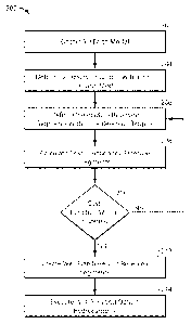
[0044] As an example of one embodiment, Figure 2 is a process flow
diagram of a
method 200 for well planning with reservoir segments in accordance with an
exemplary
embodiment of the present techniques. The blocks 202 to 212 of the method may
be
performed in the design stage prior to drilling, while block 214 may be
performed in the
operation stage.
- 11 -
CA 02897793 2015-07-09
WO 2014/123640 PCT/US2013/078013
[0045] The
method 200 may begin at block 202, where a three dimensional (3D) shared
earth model may be obtained. In some embodiments, the shared earth model may
be
generated. The shared earth model may include one or more hydrocarbon fields
with potential
reservoirs, and geographic maps for ground surface of the fields. The maps may
indicate
man-made and natural objects, such as pipelines, hazard regions, geological
features (e.g. salt
bodies and faults), existing well site platforms, and well paths. At block
204, one or more
reservoir targets may be determined within the 3D Earth model. The reservoir
targets may
include target areas in the reservoir, which are desired. The determination of
the locations
and the size of the reservoir targets or target areas may be performed based
on some
understanding and analysis of certain reservoir properties. These reservoir
properties may
include composition, quality, and connectivity to other areas of the
reservoir. The number of
reservoir targets and/or the spacing between reservoir targets may be
determined based on an
analysis of potential development strategies. As an example, the reservoir
targets may be
selected based on an unconventional resources where the subsurface targets are
equally
spaced in a predetermined grid, and/or the reservoir targets may include user
selected targets
based on geologic and engineering data inside the 3D earth model to base the
location of
potential wells.
[0046] At
block 206, the reservoir segments within the determined reservoir targets are
defined. The defining the reservoir segment may include applying weights to
various factors
that are utilized to optimize the recovery from the reservoir. For example,
the factors may
include pore pressure, fracture gradient, temperature, lithology (sand/shale),
stress orientation
and magnitude, reservoir sweet spots, 3D geo-bodies, identified drainage
boundaries and
specified locations with uncertainties. The
reservoir segments may include certain
constraints may specify basic trajectory parameters such as dog-leg severity,
kick-off depth,
hold distances and trajectory type. Anti-collision or inter-well constraints
may also be
imposed through well-to-well distance functions
[0047]
Further, the defining the reservoir segments may include defining a line or
continuous segment through the reservoir. As noted above, the defined
reservoir segments
may include a straight section defined by two points between or relative to
one or two given
reservoir surfaces, a curved section defined by two points between or relative
to one or two
given reservoir surfaces, and/or a continuous line defined by two points
between or relative to
one or two given reservoir surfaces, as noted above.
- 12 -
CA 02897793 2015-07-09
WO 2014/123640 PCT/US2013/078013
[0048] Once the reservoir segments are defined, a cost function may
optionally be
calculated for the reservoir segments, as shown in block 208. The cost
function calculation
may be performed for each reservoir segment individually and/or for two or
more reservoir
segments together. The cost function may be utilized to optimize the wellbore
trajectory
through the reservoir. The cost function may be based on minimizing net sand
or net pay
penetrated by the reservoir segment, minimizing the drilling cost and/or
maximizing
production of the hydrocarbons. Then, a determination is made whether the cost
function is
within a threshold, as shown in block 210. If the reservoir segment is not
within a specified
threshold, the reservoir segments may be redefined in block 206. This
redefining the
reservoir segments may include adjusting the factors utilized to define one or
more of the
reservoir segments.
[0049] If the reservoir segment is within a specified threshold, the
well plan may be
created based on the reservoir segments, as shown in block 212. The creation
of the well
plan may include modeling the well trajectory and/or well pads to determine
the well path,
which may involve using known techniques. The well path, well site location
and pad may
be created to limit environmental impact and perform the drilling within the
given geological
and engineering constraints. As an example, after reservoir segments are set
in the desired
location, then a common surface location (e.g., pad, drill center, etc.) may
be coupled to the
reservoir segments. In some applications, the orientation of one or more of
those reservoir
segments may not be optimal and cannot be drilled from the selected surface
location.
Accordingly, the reservoir segment may be reoriented to provide a path that
may be
generated.
[0050] Well planning may include selecting the locations of well pad,
which involves
several input considerations. These considerations include, in part, the cost
of well-site
construction, environmental impacts, the number of wells to adequately drain
the reservoir, as
well as selection of reservoir targets to position the well pads. Also,
environmental
consideration may be utilized, which include the avoidance of surface
obstacles, which may
include man-made and natural obstacles (e.g., a residential area, a river, a
road, a pipeline and
the like). The well pad may be selected to maintain a predetermined distance
from such
obstacles.
[0051] In well planning, there are numerous trade-offs between
considerations for a
single well pad (e.g., location, well design, well drilling costs, well
trajectory design, etc.)
and the economic considerations of producing and developing a hydrocarbon
field over its
- 13 -
CA 02897793 2015-07-09
WO 2014/123640 PCT/US2013/078013
full life cycle. One approach of well planning is to place the well pad as
close as possible to
the reservoir targets to reduce the cost of drilling. Another approach is to
minimize the
number of reservoir targets that are not accessible due to the surface and/or
drilling
constraints. Accordingly, this aspect of the well planning may be performed on
an ad-hoc
basis, based on modeling and/or based on solving an objective function.
[0052] A set of well trajectories starting from the slots of the well
pad can then be
designed according to well path algorithms and other engineering constraints.
In addition to
maintaining safe distances from certain obstacles (e.g., surface obstacles),
well planning also
takes into account maintaining minimum distances between the paths of the
wells and
geological features of the overburden. As a result, the well planning
parameters may include
well site configuration, maximum horizontal reach, well trajectory
constraints, anti-collision
constraints, and quality of penetration of the reservoir. Other parameters,
such as
environmental constraints, minimal stand-off distance to surface or subsurface
objects may
also be specified. In one embodiment of the present techniques, a user, such
as a geoscientist
or drilling engineer, may define well planning parameters as part of an
optimization process.
Thus, the method may create a well plan based on a combination of
environmental,
geological, and engineering constraints.
[0053] As an example, the creation of a well plan may include various
steps. The steps
may include determining a well trajectory for each of the slots in the well
pad to one of
reservoir segments. Also, the creating the well plan may include evaluating
the well pad
location and/or well trajectories based on one or more of maximizing
production of
hydrocarbons, minimizing drilling complexity, and minimizing drilling cost.
Further still, the
creating the well plan may include determining a common surface location for
the well pad;
coupling the common surface location to the one or more reservoir segments;
and evaluating
the well plan.
[0054] At block 214, the well plan may be executed and hydrocarbons may
be obtained.
The well plan execution may include providing the performing well drilling
activities based
on the well plan. The wells may be drilled at one or more of the determined
well site
locations. Well site locations may be selected for conducting detailed well
drilling activities
according to development stages of the field. For each well at the selected
locations, the
potential production, bore stability, torque, drag, and the like, may be
evaluated. Drilling
completion and performance processes, such as described in patent application
Intl. Patent
App. Pub. No. 2009/032416, may also be performed.
- 14 -
CA 02897793 2015-07-09
WO 2014/123640 PCT/US2013/078013
[0055] As an example, Figure 3 is a model representation 300 of
reservoir segments
through two reservoirs having a continuous well trajectory within the 3D earth
model in
accordance with an exemplary embodiment of the present techniques. The model
representation 300 includes a first reservoir 302 and a second reservoir 310,
which may
represent layers of rock that include hydrocarbon fluids. The first reservoir
302 includes a
first surface 303 and a second surface 304 along with a first reservoir
segment 305. The
reservoir segment 305 passes through a first target 306 in the first surface
303 and a second
target 307 in the second surface 308. Similarly, the second reservoir 310
includes a first
surface 311 and a second surface 312 along with a second reservoir segment
313. The
second reservoir segment 313 passes through a first target 314 in the first
surface 311 and a
second target 315 in the second surface 312. The continuous well trajectory
320 is a
continuous pathway within the 3D earth model that trails through reservoir
segments 305 and
313 for each potential reservoir 302 and 310.
[0056] Without planning the entire well trajectory at first, the
geoscientists direct the
analysis on the producibility of the targeted reservoirs 302 and 310 based on
reservoir
properties derived from, but not limited to seismic data, geological model
and/or reservoir
simulations. Once the reservoir segments 305 and 313 for each potential
reservoir 302 and
310 is determined. A complete well trajectory starting from a surface location
301 can then
be determined based on the engineering constraints, such as dogleg severity,
hazard
avoidance, etc. The complete well trajectory may also include geologic
constraints as well,
such as over or under pressured reservoirs, hydrates, unstable formations,
etc.
[0057] As yet another example, Figure 4 is a model representation 400 of
reservoir
segments coupled through well trajectories to a pad in accordance with an
exemplary
embodiment of the present techniques. In this model representation 400, a pad
402, which
may be a well site, facility or platform that is located on land or at sea
level, contains slots
(e.g., represented by the circles on the pad 402) in which each slot is a
starting location of a
well trajectory that reaches reservoir segments. Specifically, the well
trajectory 404 that
reaches the reservoir segment 405, the well trajectory 406 that reaches the
reservoir segment
407, the well trajectory 408 that reaches the reservoir segment 409, and the
well trajectory
410 that reaches the reservoir segment 411.
[0058] In this configuration, the pad 402 has four planned well paths
are shown by the
well trajectories 404, 406, 408 and 410 to the respective reservoir segments
405, 407, 409
and 411. In this representation 400, the four reservoir segments 405, 407, 409
and 411 are
- 15 -
CA 02897793 2015-07-09
WO 2014/123640 PCT/US2013/078013
created first and then the four well trajectories 404, 406, 408 and 410 are
planned, such that
each well trajectory 404, 406, 408 or 410 passes through at least one of the
reservoir
segments 405, 407, 409 and 411. The entire well planning process, including
the pad design
(e.g., selection of well site), selection of number of well paths as well as
the locations and
trajectories of each reservoir segment, may be performed in an interactive
process guided by
geoscientists and/or drilling engineers. The well planning process may also
include the use
of optimization algorithms. As an example, anti-collision optimization
algorithms may be
utilized to select slots in a drill center closer to the targets, etc. Other
potential optimization
technique may include an auto search within a specific area for a surface
location based on
known constraints and the same may apply to an auto search for target
locations.
[0059] As an example of another embodiment, Figure 5 is a process flow
diagram of a
method 500 for well planning with reservoir segments in accordance with an
exemplary
embodiment of the present techniques. In this method, the blocks 502 to 522
may be
performed in the design stage prior to drilling, as an alternative flow for
blocks 202 to 212 of
Figure 2. Once the design stage is complete, the operations stage may be
performed in a
manner similar to that noted above in block 214.
[0060] The method 500 may begin at block 502, where a three dimensional
(3D) earth
model may be obtained. In certain embodiments, the 3D Earth model may be
generated from
one or more of geological data objects, data models from geological analysis
and/or reservoir
simulations. The 3D earth model may include one or more hydrocarbon fields
with potential
or target reservoirs, and geographic maps for ground surface of the fields.
The maps may
indicate man-made and natural objects, such as pipelines, hazard regions,
geological features
(e.g. salt bodies and faults), existing well site platforms, and well paths.
The 3D Earth model
may include information that is utilized to optimize placement of a well pads
and/or well
paths to reservoirs. In preferred embodiments, the 3D Earth model may include
a 3D
representation of the Earth model(s) on a computer with visualization
capabilities. The
computer system could be a single processor unit or preferably a networked
multi-processor
system.
[0061] At block 504, one or more potential or target reservoirs may be
determined within
the 3D Earth model. The reservoirs may include target areas in the model that
indicate
hydrocarbons may be present (e.g., one or more hydrocarbon filled regions).
The reservoir(s)
may be bounded by two or more surfaces (e.g., a top surface and a base
surface).
- 16 -
CA 02897793 2015-07-09
WO 2014/123640 PCT/US2013/078013
[0062] Once the reservoirs are determined, one or more reservoir
segments may be
defined, as shown in block 506. The defining the reservoir segments may
include analyzing
reservoir properties, connectivity and constraints from the models to define
potential target
areas. These target areas may be utilized to identify locations to place
initial reservoir
segments. Each of the reservoir segments may extend from between the surfaces
and/or may
extend into a region adjacent to the surfaces outside the targeted reservoir.
The reservoir
segment(s) may be substantially vertical lines, but may include other
continuous lines, as
noted above. That is, these reservoir segments do not have to be confined to
reservoir areas.
An example of a substantially horizontal line as a reservoir segment is
described further
below in Figure 6A.
[0063] Once the reservoir segments are defined, one or more reservoir
segments may be
adjusted, as shown in block 508. The adjustment of the reservoir segments may
include
editing the reservoir segments positioning by adjusting the target locations
in the surfaces that
define the boundaries of the reservoir (e.g., location in the reservoir and/or
adjusting the
orientation of the reservoir segments). The adjustment may be performed to
maximize the
exposure of the reservoir segment(s) to the reservoir. Also, the adjustment
may be influenced
by various update factors: i) updated or new data as it becomes available,
which may
influence the location of the reservoir segments; b) simulation results or
other analysis
outside the 3D earth model may trigger reservoir segment location changes;
and/or c) well
path from desired surface location cannot be created because of a reservoir
segment's
orientation. Further, the target locations in the surfaces for the reservoir
segment(s) may be
adjusted individually (e.g., one of the surfaces may be locked to its
location, while the other
target location is able to move in 3D space). Alternatively, the reservoir
segment may be
adjusted with both target locations, where the two targets move or translate
in tandem
maintaining the reservoir segment(s) attitude, which is the orientation of a
planar or linear
feature in three-dimensional space (e.g., or reservoir segment(s) inclination
and azimuth), but
not its position in XY space. That is, if the target locations are locked
relative to surfaces, the
target locations may remain locked to a surface or point as the reservoir
segment is translated.
The change in orientation, length and location of the reservoir segment(s) may
be validated
and/or evaluated relative to the geological data objects and data models. This
process may
result in maximizing potential pay, minimizing risk, and/or minimizing cost of
potential
wells, as shown and discussed further in Figures 6B and 6C below.
- 17 -
CA 02897793 2015-07-09
WO 2014/123640 PCT/US2013/078013
[0064] At block 510, one or more completion intervals may be defined for
the reservoir
segments. The defining of the one or more completion intervals may include one
or more
perforations and/or completion hardware, such as sand screens and the like,
along the path of
the reservoir segment. The completion interval may be defined manually between
surfaces or
with standoff from surfaces. As the reservoir segment is edited and re-
positioned
perforations along the reservoir segment may be configured to update based
upon their
initialization criteria. An example is discussed further below with reference
to Figure 6D.
[0065] At block 512, the reservoir segments may be verified. This
verification may
include testing the quality of the location of the reservoir segment(s) in a
simulation and/or
geologic model to validate their potential as producer or injector candidates.
As the reservoir
segments are edited, data may be extracted from the reservoir model(s) or
seismic and
provided to a user via a display or graphical interface to convey certain
information regarding
the quality of the location within the reservoir. Vertical planes along the
well bore with
textures of extracted model properties or extracted model properties from the
intersection of
the well and model displayed as well logs can be used to visualize and further
verify the
quality of the reservoir segment position. Further, the engineering
constraints and geological
constraints, such as safe distance to certain geological objects, may also be
utilized to verify
the reservoir segments. Violations of these constraints may include
notification to the user
via a display or other suitable indication. In certain embodiments, the result
provided from
this verification may provide an optimal location for the reservoir segment(s)
before it is
connected to a surface location, which is discussed further in Figure 6C.
Further, the process
may also include a flow from block 512 to block 508, in the event that one or
more
adjustments are to be performed on the reservoir segments, as a result of one
or more update
factors.
[0066] At block 514, a determination is made whether updated data is
available. The
updated data may include additional survey data, analysis and/or modeling of
the subsurface
region. If updated data is available, the method proceeds to block 508 to
adjust one or more
of the reservoir segments. However, if the updated data is not available, well
pad locations
and well trajectories may be calculated, as noted in block 516. The well pad
locations and
well trajectories may be calculated to reach the defined reservoir segments,
which may
include determining optimal location for the well trajectories. Also, the well
pad locations
and well trajectory should satisfy the engineering constraints and/or
geological constraints
That is, the calculation may include well trajectories from a well pad (e.g.,
a common surface
- 18 -
CA 02897793 2015-07-09
WO 2014/123640 PCT/US2013/078013
location or drill center) to the one or more reservoir segments, such that the
path defined is a
viable and a drillable path defined by industry drilling physics. The well pad
may be
relocated to address geographic obstacles at the surface, ocean floor or
subsurface. Examples
of wells paths attached to the well pad are described further below in Figures
7A to 7C.
[0067] Then, at block 518, a determination is made whether the drilling
parameters from
the well trajectory satisfy a threshold. The threshold may be calculated from
an objective
function and/or may be based on a user's decision. The determination may be
performed for
each of the well trajectories individually and/or for a combination of two or
more well
trajectories. If the drilling parameters do not satisfy the drilling
parameters, then a
determination is made to adjust one or more of the reservoir segments, well
pad location
and/or well trajectory, as shown in block 520. Then, the process may continue
to blocks 508
to 518 to update the various aspects of the well plan.
[0068] If
the drilling parameters do satisfy the threshold, then an assessment of
drilling
parameters, such as well completions and/or perforations, as shown in block
522. This may
include storing the well plan and/or communicating the well plan for the
operations stage.
The well plan created from this process is a substantially drill ready before
is handed to the
drilling engineer or drilling contractor for final approval. As an example,
the drilling team
may have specific rules that need to be satisfied when building a well path.
If the reservoir
segment is in a location that permits the connection to a specific surface
location and the rules
are satisfied, then other detailed planning may be performed. This additional
detailed
planning may include determining how and where to complete the well, whether
it is open to
flow or injection, casing points, etc.
[0069] In
one or more embodiments, the method may include analysis of other data
and/or cost functions to evaluate the one or more of the reservoir segments
(e.g., individually
or in a group). The evaluation of the reservoir segments may include comparing
one or more
of geographic data, geological data and seismic data associated with the
subsurface region
with the reservoir segments to verify the reservoir segments. The verification
may include
determining if one or more of the reservoir segments do not optimize a cost
function or do
not satisfy certain criteria. The
geographic data may include topography data,
surface/submarine infrastructure (e.g., roads, houses, buildings, pipelines,
etc.); the geologic
data may include the type of rock (e.g., lithology), structural framework,
hazards (e.g.,
pressurized or under pressurized formations, etc.); and the seismic data may
include
measured data that is a proxy for some of the geologic features above. If the
reservoir
- 19 -
CA 02897793 2015-07-09
WO 2014/123640 PCT/US2013/078013
segments do not satisfy the cost function or do not satisfy the verification,
one or more of the
reservoir segments may be updated. As noted above, the reservoir segments may
be updated
by changing one or more of inclination, orientation and location of the
reservoir segments to
optimize the cost function or based on the comparison (e.g., to satisfy the
verification or
satisfy the certain criteria).
[0070] The proposed methods may be utilized for depletion planning of a
field. When
potential reservoirs have been identified in the subsurface, the next stage is
to plan a number
of wells to extract the hydrocarbons and to support the pressure needed to
maximize the
recovery of the resources. Reservoir segments (e.g., reservoir completion
sections) are
created in a 3D modeling environment with existing geologic and simulation
models together
with other pertinent data to determine the most optimal location for the
potential drill wells.
Once the locations are decided, complete well plans are created to connect the
one or more
common surface locations (e.g., well pads or drill centers) with the reservoir
segments.
[0071] Also, the above methods may also be useful for individual well
planning in
addition to field planning. That is, the workflow may also be useful when
planning
individual wells that involve planning to maximize potential injectivity
and/or producibility.
For these well plans, close interrogation with simulation models is useful to
determine the
optimal location before creating a complete well. As such, the described
process further
enhances the well planning methods.
[0072] As an example of the above methods is described further in Figures
6A to 6D and
7A to 7C. Figures 6A to 6D are exemplary modeled representations of a
subsurface region
including reservoirs and reservoir segments in accordance with an exemplary
embodiment of
the present techniques. Similarly, Figures 7A to 7C are exemplary modeled
representations
of a subsurface region including reservoirs, well trajectories and reservoir
segments in
accordance with an exemplary embodiment of the present techniques. Similar
reference
numerals may be utilized for similar features within the model
representations.
[0073] As shown in Figure 6A, the modeled region 600 includes reservoir
segments 606,
608, 610 and 612 that are substantially perpendicular straight lines between
the surfaces 602
and 604. The oil water contact (OWC) 603 may be a representation of a
substantially
horizontal surface within the modeled region 600. This modeled region 600 may
represent
the initial stage of positioning the reservoir segments. For example, this
modeled
representation 600 may be the reservoir segments defined in block 206 of
Figure 2 and/or in
block 506 of Figure 5.
- 20 -
CA 02897793 2015-07-09
WO 2014/123640 PCT/US2013/078013
[0074] As shown in Figure 6B, the modeled region 620 includes reservoir
segments 626,
628, 630 and 632 that are deviated lines oriented between the surfaces 602 and
604. This
modeled region 600 may represent the adjustments and/or optimizations to the
positioning the
reservoir segments. For example, this modeled representation 620 may be the
reservoir
segments defined in one or more of blocks 206 to 210 of Figure 2 and/or in one
or more of
blocks 508 and 520 of Figure 5.
[0075] As shown in Figure 6C, the modeled region 640 includes reservoir
segments 626,
and 630 that are deviated lines oriented between the surfaces 602 and 604.
This modeled
region 600 may represent the verification of the reservoir segments. To
provide verification,
the process may include representative logs (e.g., pseudo logs) and/or
vertical planes from
geologic data and/or seismic data, which is represented by data planes 642 and
644. The data
planes 642 and 644 may include extracted properties from seismic, geologic
and/or
simulation models. For example, this modeled representation 640 may be the
reservoir
segments defined in one or more of blocks 206 to 210 of Figure 2 and/or in one
or more of
blocks 512 and 514 of Figure 5.
[0076] As shown in Figure 6D, the modeled region 660 includes reservoir
segments 626,
628, 630 and 632 that are deviated lines oriented between the surfaces 602 and
604. This
modeled region 600 may represent the placement of completion intervals 662,
664, 666 and
668 (e.g., completion or perforation intervals) associated with the reservoir
segments. For
example, this modeled representation 660 may be the defining of the completion
intervals for
the respective reservoir segments defined in blocks 206 to 210 of Figure 2
and/or in block
510 of Figure 5.
[0077] Beneficially, the modeled regions 620, 630 and 640 provide useful
information
that may be utilized to enhance the process. Specifically, the modeled regions
620, 630 and
640 (e.g., portions of an earth model) provide information that may aid in the
proper
orientation/optimization of the reservoir segment's location, including the
design of
completion intervals. The specific design of the reservoir segments may depend
on whether
the reservoir is to be developed by production and/or injection techniques.
[0078] As shown in Figure 7A, the modeled region 700 includes well
trajectories 704,
706, 708 and 710 from a well pad 702 to the reservoir segments 626, 628, 630
and 632. This
modeled region 700 may represent the placement of well paths to a common
surface location
or drill center, which is the well pad 702. The well trajectories 704, 706,
708 and 710 may
each be associated with one of the reservoir segments 626, 628, 630 and 632.
For example,
- 21 -
CA 02897793 2015-07-09
WO 2014/123640 PCT/US2013/078013
this modeled representation 700 may be the creating or calculating of a well
plan in blocks
212 of Figure 2 and/or the in block 516 to 522 of Figure 5.
[0079] As shown in Figure 7B, the modeled region 720 includes well
trajectories 704,
706, 708 and 710 from a well pad 702 to the reservoir segments 626, 628, 630
and 632 from a
top perspective view. This modeled region 720 may represent relocation of the
well pad 702
via an interactive process and/or optimization process for the selected
reservoir segments
626, 628, 630 and 632. For example, this modeled representation 720 may be the
creating or
calculating of a well plan in blocks 212 of Figure 2 and/or the in block 516
to 522 of Figure
5.
[0080] As shown in Figure 7C, the modeled region 730 includes well
trajectories 704,
706, 708 and 710 from a well pad 732 to the reservoir segments 626, 628, 630
and 632 from a
top perspective view. This modeled region 723 may represent relocation of the
well pad 732
via an interactive process and/or optimization process for the selected
reservoir segments
626, 628, 630 and 632. For example, this modeled representation 730 may be the
creating or
calculating of a well plan in blocks 212 of Figure 2 and/or the in block 516
to 522 of Figure
5.
[0081] Beneficially, the modeled regions 700, 720 and 730 provide a
different
perspective on the useful information that may be utilized to enhance the
process.
[0082] Persons skilled in the technical field will readily recognize
that in practical
applications of the disclosed methodology, it is partially performed on a
computer, typically a
suitably programmed digital computer. Further, some portions of the detailed
descriptions
which follow are presented in terms of procedures, steps, logic blocks,
processing and other
symbolic representations of operations on data bits within a computer memory.
These
descriptions and representations are the means used by those skilled in the
data processing
arts to most effectively convey the substance of their work to others skilled
in the art. In the
present application, a procedure, step, logic block, process, or the like, is
conceived to be a
self-consistent sequence of steps or instructions leading to a desired result.
The steps are
those requiring physical manipulations of physical quantities. Usually,
although not
necessarily, these quantities take the form of electrical or magnetic signals
capable of being
stored, transferred, combined, compared, and otherwise manipulated in a
computer system.
- 22 -
CA 02897793 2015-07-09
WO 2014/123640 PCT/US2013/078013
[0083] It should be borne in mind, however, that all of these and
similar terms are to be
associated with the appropriate physical quantities and are merely convenient
labels applied
to these quantities. Unless specifically stated otherwise as apparent from the
following
discussions, it is appreciated that throughout the present application,
discussions utilizing the
terms such as "processing" or "computing", "calculating", "determining",
"displaying",
"copying," "producing," "storing," "adding," "applying," "executing,"
"maintaining,"
"updating," "creating," "constructing" "generating" or the like, refer to the
action and
processes of a computer system, or similar electronic computing device, that
manipulates and
transforms data represented as physical (electronic) quantities within the
computer system's
registers and memories into other data similarly represented as physical
quantities within the
computer system memories or registers or other such information storage,
transmission or
display devices.
[0084] Embodiments of the present techniques also relate to an apparatus
for performing
the operations herein. This apparatus may be specially constructed for the
required purposes,
or it may comprise a general-purpose computer selectively activated or
reconfigured by a
computer program stored in the computer (e.g., one or more sets of
instructions). Such a
computer program may be stored in a computer readable medium. A computer-
readable
medium includes any mechanism for storing or transmitting information in a
form readable
by a machine (e.g., a computer). For example, but not limited to, a computer-
readable (e.g.,
machine-readable) medium includes a machine (e.g., a computer) readable
storage medium
(e.g., read only memory ("ROM"), random access memory ("RAM"), magnetic disk
storage
media, optical storage media, flash memory devices, etc.), and a machine
(e.g., computer)
readable transmission medium (electrical, optical, acoustical or other form of
propagated
signals (e.g., carrier waves, infrared signals, digital signals, etc.)).
[0085] Furthermore, as will be apparent to one of ordinary skill in the
relevant art, the
modules, features, attributes, methodologies, and other aspects of the
invention can be
implemented as software, hardware, firmware or any combination of the three.
Of course,
wherever a component of the present invention is implemented as software, the
component
can be implemented as a standalone program, as part of a larger program, as a
plurality of
separate programs, as a statically or dynamically linked library, as a kernel
loadable module,
as a device driver, and/or in every and any other way known now or in the
future to those of
skill in the art of computer programming. Additionally, the present techniques
are in no way
limited to implementation in any specific operating system or environment.
- 23 -
CA 02897793 2015-07-09
WO 2014/123640 PCT/US2013/078013
[0086] As an example, a computer system may be utilized and configured
to implement
on or more of the present aspects. The computer system may include a plurality
of
processors; memory in communication with the processors; and a set of
instructions stored on
the memory and accessible by the processors, wherein the set of instructions,
when executed,
are configured to: obtain a three dimensional (3D) Earth model representing a
subsurface
region; determine one or more reservoir targets within the 3D Earth model;
define one or
more reservoir segments in the 3D Earth model, wherein each of the reservoir
segments pass
through at least a portion of one of the target reservoirs; evaluate the
reservoir segments; and
create a well plan based on the reservoir segments to provide a fluid flow
path from the one
or more reservoir targets to a well pad from one or more of the reservoir
segments. In certain
embodiments, the set of instructions may perform the different aspects in the
methods noted
above or the algorithm noted above.
[0087] As an example, the techniques discussed herein may be implemented
on a
computing device, such as that shown in Figure 8. Figure 8 shows an exemplary
computer
system 800 on which software for performing processing operations of
embodiments of the
present techniques may be implemented. A central processing unit (CPU) 802 is
coupled to a
system bus 804. The CPU 802 may be any general-purpose CPU. The present
techniques are
not restricted by the architecture of CPU 802 (or other components of
exemplary system 800)
as long as the CPU 802 (and other components of system 800) supports
operations according
to the techniques described herein.
[0088] The CPU 802 may execute the various logical instructions
according to the
disclosed techniques. For example, the CPU 802 may execute machine-level
instructions for
performing processing according to the exemplary operational flow described
above, such as
in conjunction with Figures 2 and 5. As a specific example, the CPU 802 may
execute
machine-level instructions for performing the methods of Figures 2 and 5.
[0089] The computer system 800 may also include random access memory
(RAM) 806,
which may be SRAM, DRAM, SDRAM, or the like. The computer system 800 may
include
read-only memory (ROM) 808 which may be PROM, EPROM, EEPROM, or the like. The
RAM 806 and the ROM 808 hold user and system data and programs, as is well
known in the
art. The programs may include code stored on the RAM 806 that may be used for
modeling
geologic properties with homogenized mixed finite elements, in accordance with
embodiments of the present techniques.
- 24 -
CA 02897793 2016-11-02
[0090] The computer system 800 may also include an input/output (I/0)
adapter 810, a
communications adapter 822, a user interface adapter 824, and a display
adapter 818. The
I/0 adapter 810, user interface adapter 824, and/or communications adapter 822
may, in
certain embodiments, enable a user to interact with computer system 800 to
input
information. Further, the computer system 800 may also include a graphical
processing unit
(GPU(s)) 814 to enhance the graphical processing of the computer system 800.
[0091] The I/0 adapter 810 may connect the bus 804 to storage device(s)
812, such as
one or more of hard drive, compact disc (CD) drive, floppy disk drive, tape
drive, flash
drives, USB connected storage, etc. to computer system 800. The storage
devices may be
used when RAM 806 is insufficient for the memory requirements associated with
storing data
for operations of embodiments of the present techniques. For example, the
storage device
812 of computer system 800 may be used for storing such information as
computational
meshes, intermediate results and combined data sets, and/or other data used or
generated in
accordance with embodiments of the present techniques.
[0092] The communications adapter 822 is adapted to couple the computer
system 800 to
a network (not shown), which may enable information to be input to and/or
output from the
system 800 via the network, for example, the Internet or other wide-area
network, a local-
area network, a public or private switched telephone network, a wireless
network, or any
combination of the foregoing. The user interface adapter 824 couples user
input devices,
such as a keyboard 828, a pointing device 826, and a microphone (not shown)
and/or output
devices, such as speaker(s) (not shown) to computer system 800. The display
driver 816 and
display adapter 818 are driven by the CPU 802 to control the display on the
display device
820, for example, to display information pertaining to a target area under
analysis, such as
displaying a generated representation of the computational mesh, the
reservoir, or the target
area, according to certain embodiments.
[0093] The present techniques are not limited to the architecture of the
computer system
800 shown in Figure 8. For example, any suitable processor-based device may be
utilized for
implementing all or a portion of embodiments of the present techniques,
including without
limitation personal computers, laptop computers, computer workstations, and
multi-processor
servers. Moreover, embodiments may be implemented on application specific
integrated
circuits (ASICs) or very large scale integrated (VLSI) circuits. In fact,
persons of ordinary
skill in the art may utilize any number of suitable structures capable of
executing logical
operations according to the embodiments. In one embodiment of the present
techniques, the
-25 -
CA 02897793 2015-07-09
WO 2014/123640 PCT/US2013/078013
computer system may be a networked multi-processor system.
[0094] One or more of the following embodiments in the following
paragraphs may be
utilized with the processes, apparatus, and systems, provided above, to
prepare a model
and/or be utilized to produce hydrocarbons:
1. A method for obtaining hydrocarbons comprising: obtaining a three
dimensional
(3D) Earth model representing a subsurface region; determining one or more
reservoir targets
within the 3D Earth model; defining one or more reservoir segments in the 3D
Earth model,
wherein each of the reservoir segments pass through at least a portion of one
of the target
reservoirs; evaluating the reservoir segments; and creating a well plan based
on the reservoir
segments to provide a fluid flow path from the one or more reservoir targets
to a well pad
through the one or more of the reservoir segments.
2. The method of paragraph 1, wherein evaluating the reservoir segments
comprises:
calculating a cost function that minimizes net sand or net pay penetrated by
one and/or more
of the reservoir segments based on one or more of the reservoir segments; and
determining
whether the calculated cost function is within a threshold.
3. The method of paragraph 1, wherein evaluating the reservoir segments
comprises:
calculating a cost function that minimizes the drilling cost and/or maximizes
production of
hydrocarbons based on one or more of the reservoir segments; and determining
whether the
calculated cost function is within a threshold.
4. The method of any one of paragraphs 1 to 3, wherein evaluating the
reservoir
segments comprises: obtaining one or more of geographic data, geological data
and seismic
data associated with the subsurface region; comparing the one or more of
geographic data,
geological data and seismic data associated with the subsurface region with
the reservoir
segments to verify the reservoir segments.
5. The method of paragraph 4, wherein geographic data comprises one or more
of
topography data and infrastructure data.
6. The method of any one of paragraphs 4 to 5, wherein geologic data
comprises one
or more of type of rock; structural framework and hazards.
7. The method of any one of paragraphs 2 to 6, further comprising updating
the
reservoir segments if the cost function does not satisfy the threshold.
- 26 -
CA 02897793 2015-07-09
WO 2014/123640 PCT/US2013/078013
8. The method of any one of paragraphs 2 or 7, wherein the reservoir
segments are
updated by changing one or more of inclination, orientation and location of
the reservoir
segments to optimize the cost function or based on the comparison.
9. The method of any one of paragraphs 1 to 8, wherein creating the well
plan
comprises determining a well trajectory for each of a plurality of slots in
the well pad to one
of the one or more reservoir segments.
10. The method of any one of paragraphs 1 to 9, wherein creating the well
plan
comprises evaluating the well pad location and well trajectories based on one
or more of
maximizing production of hydrocarbons, minimizing drilling complexity, and
minimizing
1 0 drilling cost.
11. The method of any one of paragraphs 1 to 10, wherein creating the well
plan
comprises: determining a common surface location for the well pad; coupling
the common
surface location to the one or more reservoir segments; and evaluating the
well plan.
12. The method of paragraph 11, wherein evaluating the well plan comprises
1 5 determining whether the drilling parameters are satisfied by the well
plan.
13. The method of any one of paragraphs 1 to 12, wherein creating the well
plan
comprises determining whether a pad location and well trajectory satisfy the
engineering
constraints and/or geological constraints.
14. The method of any one of paragraphs 1 to 13, wherein the one or more
reservoir
20 segments comprise a straight section defined by two points between or
relative to one or two
surfaces.
15. The method of any one of paragraphs 1 to 13, wherein the one or more
reservoir
segments comprise a curved section defined by two points between or relative
to one or two
surfaces.
25 16. The method of any one of paragraphs 1 to 13, wherein the one
or more reservoir
segments comprise a continuous line defined by two points between or relative
to one or two
surfaces.
17. The method of any one of paragraphs 1 to 16, comprising defining
one or more
completion intervals after the one or more reservoir segments are defined;
wherein the one or
30 more completion intervals comprise one or more perforations and/or
completion hardware.
- 27 -
CA 02897793 2015-07-09
WO 2014/123640 PCT/US2013/078013
18. The method of any one of paragraphs 1 to 17, further comprising:
drilling one or
more wellbore based on the well plan; producing hydrocarbons from the one or
more
wellbores.
19. A system for well planning comprising: a processor; memory coupled to
the
processor; and a set of instructions stored in the memory and accessible by
the processor,
wherein the set of instructions, when executed, are configured to: obtain a
three dimensional
(3D) Earth model representing a subsurface region; determine one or more
reservoir targets
within the 3D Earth model; define one or more reservoir segments in the 3D
Earth model,
wherein each of the reservoir segments pass through at least a portion of one
of the target
reservoirs; evaluate the reservoir segments; and create a well plan based on
the reservoir
segments to provide a fluid flow path from the one or more reservoir targets
to a well pad
from one or more of the reservoir segments.
20. The system of paragraph 19, wherein the set of instructions to evaluate
the
reservoir segments are configured to: calculate a cost function that minimizes
net sand or net
pay penetrated by one and/or more of the reservoir segments based on one or
more of the
reservoir segments; and determine whether the calculated cost function is
within a threshold.
21. The system of paragraph 19, wherein the set of instructions to evaluate
the
reservoir segments are configured to: calculate a cost function that minimizes
the drilling cost
and/or maximizes production of hydrocarbons based on one or more of the
reservoir
segments; and determine whether the calculated cost function is within a
threshold.
22. The system of any one of paragraphs 19 to 23, wherein the set of
instructions to
evaluate the reservoir segments are configured to: obtain one or more of
geographic data,
geological data and seismic data associated with the subsurface region;
compare the one or
more of geographic data, geological data and seismic data associated with the
subsurface
region with the reservoir segments to verify the reservoir segments.
23. The system of paragraph 22, wherein the set of instructions are
configured to
obtain geographic data from memory, wherein the geographic data comprises one
or more of
topography data and infrastructure data.
24. The system of any one of paragraphs 22 to 23, wherein the set of
instructions are
configured to obtain geologic data from memory, wherein geologic data
comprises one or
more of type of rock; structural framework and hazards.
- 28 -
CA 02897793 2015-07-09
WO 2014/123640 PCT/US2013/078013
25. The system of any one of paragraphs 22 to 24, wherein the set of
instructions are
configured to update the reservoir segments if the cost function does not
satisfy the threshold.
26. The system of any one of paragraphs 22 or 25, wherein the set of
instructions are
configured to update the reservoir segments by changing one or more of
inclination,
orientation and location of the reservoir segments to optimize the cost
function or based on
the comparison.
27. The system of any one of paragraphs 19 to 26, wherein the set of
instructions to
create the well plan are configured to determine a well trajectory for each of
a plurality of
slots in the well pad to one of the one or more reservoir segments.
28. The system of any one of paragraphs 19 to 27, wherein the set of
instructions to
create the well plan are configured to evaluate the well pad location and well
trajectories
based on one or more of maximizing production of hydrocarbons, minimizing
drilling
complexity, and minimizing drilling cost.
29. The system of any one of paragraphs 19 to 28, wherein the set of
instructions to
create the well plan is configured to:
determine a common surface location for the well pad;
couple the common surface location to the one or more reservoir segments; and
evaluate the well plan.
30. The system of paragraph 29, wherein the set of instructions to create
the well plan
are configured to determine whether the drilling parameters are satisfied by
the well plan.
31. The system of any one of paragraphs 19 to 30, wherein the set of
instructions to
create the well plan are configured to determine whether a pad location and
well trajectory
satisfy the engineering constraints and/or geological constraints.
32. The system of any one of paragraphs 19 to 30, wherein the set of
instructions are
configured to calculate the one or more reservoir segments of a straight
section defined by
two points between or relative to one or two surfaces.
33. The system of any one of paragraphs 19 to 30, wherein the set of
instructions are
configured to calculate the one or more reservoir segments of a curved section
defined by two
points between or relative to one or two surfaces.
- 29 -
CA 02897793 2015-07-09
WO 2014/123640 PCT/US2013/078013
34. The system of any one of paragraphs 19 to 30, wherein the set of
instructions are
configured to calculate the one or more reservoir segments of a continuous
line defined by
two points between or relative to one or two surfaces.
35. The system of any one of paragraphs 19 to 34, wherein the set of
instructions are
configured to define one or more completion intervals after the one or more
reservoir
segments are defined; wherein the one or more completion intervals comprise
one or more
perforations and/or completion hardware.
36. The system of any one of paragraphs 19 to 35, wherein the set of
instructions are
configured to: drill one or more wellbores based on the well plan; and produce
hydrocarbons
1 0 from the one or more wellbores.
[0095] While the present techniques may be susceptible to various
modifications and
alternative forms, the exemplary embodiments discussed above have been shown
only by
way of example. However, it should again be understood that the present
techniques are not
intended to be limited to the particular embodiments disclosed herein. Indeed,
the present
1 5 techniques include all alternatives, modifications, and equivalents
falling within the true spirit
and scope of the appended claims.
- 30 -