Note: Descriptions are shown in the official language in which they were submitted.
CA 02897797 2016-05-31
PRODUCING HYDROCARBONS FROM A FORMATION
CROSS-REFERENCE TO RELATED APPLICATION
[0001] This application claims the priority benefit of U.S. Provisional
Patent
Application 61/780,028 filed 13 March 2013 entitled PRODUCING HYDROCARBONS
FROM A
FORMATION.
BACKGROUND
Fields of Embodiments
[0002] The disclosure relates generally to the field of producing
hydrocarbons from a
formation.
Description of Related Art
[0003] This section is intended to introduce various aspects of the art,
which may be
associated with exemplary embodiments of the present disclosure. This
discussion is
believed to assist in providing a framework to facilitate a better
understanding of particular
aspects of the present disclosure. Accordingly, it should be understood that
this section
should be read in this light, and not necessarily as admissions of prior art.
[0004] Substantial volumes of hydrocarbons exist in low-permeability and
high-
permeability formations around the world. Low-permeability formations may be
formations
that are near horizontal wells with multiple fracture stimulations distributed
along the well
and required to produce fluids from the formation at economic rates. For
example, low-
permeability formations may be less than or equal to 10 millidarcies (mD)
while high-
permeability formations may be formations that are greater than 10 mD. Low-
permeability
formations may be predominantly sandstone, carbonate, or shale and/or may have
some high-
permeability streaks. High-permeability formations may have some low-
permeability
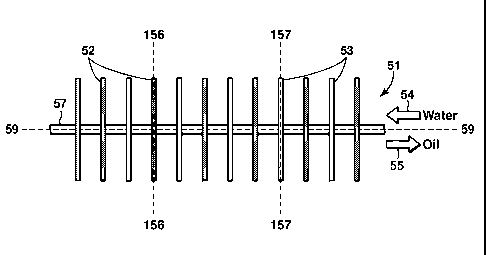
streaks. From a practical perspective low permeability reservoirs may require
horizontal
wells with one or more hydraulic fracture stimulations to achieve economic
production rates
while high permeability reservoirs may be economically exploited with vertical
or horizontal
wells and may not require hydraulic fracture stimulations.
[0005] During primary production natural reservoir energy drives
hydrocarbons from
the reservoir and into the wellbore. Initially, the reservoir pressure is
considerably higher
than the bottomhole pressure inside the wellbore. This high natural
differential pressure
1
CA 02897797 2015-07-09
WO 2014/158333 PCT/US2014/013225
drives hydrocarbons toward the well. During primary production the reservoir
pressure
declines as fluids are removed from the formation. The natural reservoir
energy exploited in
primary production such as oil and water expansion, evolution and expansion of
gas initially
dissolved in the oil, and rock compaction have limited ability to compensate
for the volume
of produced hydrocarbons and thereby to mitigate the pressure decline. As the
reservoir
pressure declines because of production, so does the differential pressure
between the
reservoir and wellbore, resulting in declining production rates. Primary
production ends
when the pressure is so low that the hydrocarbon production rate is no longer
economical.
Recovery during primary production is typically less than 15%. The lower the
permeability
of the formation the more difficult it is for pressure and fluid to be
transmitted towards the
well. This results in lower initial rates, more rapid pressure decline, and
lower recovery of
hydrocarbons.
[0006] Production of hydrocarbons from high-permeability formations often
results in
more satisfactory recovery rates than low-permeability formations. The
recovery rate of
hydrocarbons in high-permeability formations can be as high as 75%. To achieve
these
higher rates, different drive mechanisms may be used. For example, water
injection or gas
injection may be used to provide pressure support and to displace
hydrocarbons. Other
processes, such as injecting miscible gases, surfactants, solvents, polymers,
or steam may
also be used to help improve hydrocarbon recovery.
[0007] To increase the recovery rate of hydrocarbons during primary
production from
low-permeability formations, operators have tried using various well types and
configurations, different well stimulation methods and processes that exploit
different drive
mechanisms during and after primary production. For example, operators have
tried closely
spaced vertical and horizontal wells, wells that have been stimulated using a
variety of
methods such as hydraulic fracturing, acid injection or acid fracturing.
Stimulation methods
increase the productivity of a well, enabling a well to initially produce
hydrocarbons at a
higher rate. Additionally, operators have tried some of the same drive-
mechanisms used in
high-permeability formations, such as water-flooding or gas-flooding, after
fracturing during
primary production. One well design that is commonly employed in low
permeability
formations, as shown in Figure 1, consists of installing a horizontal well 1
and creating
fractures 2 that emanate from the wellbore 5 of the well 1 to recover the
hydrocarbons. As
shown in Figure 2, stimulated horizontal wells can be utilized for water-
flooding by a method
that entails operators installing a well 100 and injecting water so that the
water displaces
2
CA 02897797 2015-07-09
WO 2014/158333 PCT/US2014/013225
hydrocarbons toward producer wells 4, 204. Gas-flooding is similar to water-
flooding, but
entails injecting into a well instead of water to displace hydrocarbons to a
production well.
[0008] Although fracturing can help primary production from a low
permeability
formation to be more economically attractive by increasing initial production
rates, the
process has two major disadvantages. First, due to rapid pressure decline in
the wellbore
region, the production rate of recovered hydrocarbons typically declines
quickly to less than
25% of the initial rate of recovery within a year. Second, the total
percentage of recovered
hydrocarbons relative to the hydrocarbons contained in the formation is low.
Often, the total
percentage of recovered hydrocarbons is less than 15%. The low formation
permeability and
resulting low rate of pressure diffusion through the reservoir, results in
rapid pressure decline
at the well and rapidly declining production rates of hydrocarbons.
Furthermore, since
primary production processes rely on fluid expansion as their drive mechanisms
they tend to
have very low recovery levels in all oil reservoirs.
[0009] Disadvantages also result when operators use water-flooding or gas-
flooding
after using fracturing during primary production in a low-permeability
formation. These
processes have the potential to increase recovery of hydrocarbons to 20% or
more. However,
they require the drilling and fracturing of additional injection wells or the
conversion of
existing production wells into injection wells. Because of the low
permeability, the injection
wells need to be relatively close to the producing well to provide sufficient
pressure support
and achieve economic rates. Nonetheless, water-flooding in low-permeability
formations is
often limited by low injection rates due to the low-permeability formation,
injection pressure
constraints, plugging, separation between the wells and relative permeability
effects. A key
limiting factor is that if the injection wells are placed in close proximity
to the production
wells, the fractures from the wells may intersect. This results in high
conductivity pathways
between the wells that severely limit the rate of hydrocarbon production and
the overall
recovery that can be economically achieved. Gas-flooding in low-permeability
formations is
often limited by poor sweep due to gravity override, viscous fingering and
heterogeneity
contrast. These detrimental effects often cause fractures to intersect,
thereby eliminating the
pressure difference needed for sweep to occur. These disadvantages are often
exacerbated in
low-permeability formations because of tight well spacing and higher
permeability streaks.
[0010] Additional disadvantages may also result when the aforementioned
drive
mechanisms are used in low-permeability or high-permeability formations. The
effectiveness
of water injection for improved recovery is sometimes adversely affected by
reduced
3
CA 02897797 2015-07-09
WO 2014/158333 PCT/US2014/013225
injectivity due to plugging of injection wells with solids, scale, oil, etc.
Enhanced recovery
techniques, such as injection of miscible gases, surfactants, solvents,
polymers, modified
brines, or steam can sometimes be applied to high permeability reservoirs to
improve
recovery, but the use of these techniques is often uneconomic. There is a
significant time
difference between when these relatively expensive fluids are injected into an
injection well
when that incremental hydrocarbon production occurs at a producing well.
[0011] A need exists for improved technology, including technology that
may address
one or more of the above described disadvantages of conventional ways of
producing
hydrocarbons from a formation.
SUMMARY
[0012] A method of producing hydrocarbons from a formation may include
drilling a
wellbore in the formation, wherein the wellbore is approximately horizontal;
forming two or
more fractures in the formation from the wellbore; receiving fracture
performance data about
the two or more fractures; analyzing the fracture performance data; selecting
one or more
fractures for injection and selecting one or more fractures for production
based on the
analysis of the fracture performance data; and completing the wellbore such
that injection
into the one or more fractures selected for injection and production from the
one or more
fractures selected for production may occur simultaneously.
[0013] A method of producing hydrocarbons from a formation may include
drilling a
wellbore in a formation; forming a first fracture in the formation that
emanates from the
wellbore; forming a second fracture in the formation that emanates from the
wellbore and is
substantially parallel to the first fracture; and simultaneously (a) injecting
a fluid, that
increases pressure in an area of the formation adjacent to the first fracture,
from an injection
tubing string in communication with the second fracture and (b) producing
hydrocarbons
from the first fracture into a production tubing string that is substantially
parallel to the
injection tubing string. The wellbore is approximately horizontal.
[0014] A method of producing hydrocarbons from a formation may include
drilling a
first wellbore in a formation, wherein the first wellbore is approximately
horizontal; forming
a first fracture in the formation that emanates from the first wellbore;
forming a second
fracture in the formation that emanates from the first wellbore and is
substantially parallel to
the first fracture; sealing an opening to one of the first fracture and the
second fracture with a
sealing element; drilling a second wellbore in the formation that is
approximately horizontal
4
CA 02897797 2015-07-09
WO 2014/158333 PCT/US2014/013225
and substantially parallel to the first wellbore, wherein the second wellbore
intersects the first
fracture and the second fracture; and simultaneously (a) injecting a fluid,
that increases
pressure in an area of the formation adjacent to the first fracture, from the
second wellbore to
the second fracture and (b) producing hydrocarbons that travel from the first
fracture into the
first wellbore.
[0015] A method of producing hydrocarbons from a formation may include
drilling a
first wellbore in a formation, wherein the first wellbore is approximately
horizontal; forming
a first fracture in the formation that emanates from the first wellbore;
drilling a second
wellbore in the formation that is approximately horizontal and substantially
parallel to the
first wellbore; forming a second fracture in the formation that emanates from
the second
wellbore and is substantially parallel to the first fracture, wherein the
first fracture intersects
the second wellbore and the second fracture intersects the first wellbore; and
simultaneously
(a) injecting a fluid, that increases pressure in an area of the formation
adjacent to the first
fracture, from the second wellbore to the second fracture and (b) producing
hydrocarbons that
travel from the first fracture into the first wellbore.
[0016] A system for producing hydrocarbons from a formation may include
an
approximately horizontal wellbore in a formation, the wellbore including an
injection tubing
string and a production tubing string that is substantially parallel to the
injection tubing
string; a first fracture in the formation that emanates from the wellbore; a
second fracture in
the formation that emanates from the wellbore and that is substantially
parallel to the first
fracture; wherein the second fracture is constructed and arranged to receive a
fluid injected
into the injection tubing string that increases pressure in the formation in
an area adjacent to
the first fracture, and wherein the first fracture is constructed and arranged
to receive
hydrocarbons when the second fracture receives the fluid.
[0017] The foregoing has broadly outlined some of the features of the
present
disclosure in order that the detailed description that follows may be better
understood.
Additional features will also be described herein.
BRIEF DESCRIPTION OF THE DRAWINGS
[0018] These and other features, aspects and advantages of the disclosure
will become
apparent from the following description, appending claims and the accompanying
exemplary
features shown in the drawings, which are briefly described below.
[0019] Figure 1 is a top, schematic view of a conventional well.
CA 02897797 2015-07-09
WO 2014/158333 PCT/US2014/013225
[0020] Figure 2 is a top, schematic view of conventional production well
and a
conventional injection well.
[0021] Figure 3 is a top, schematic view of a well.
[0022] Figure 4 is a top, schematic view of a well.
[0023] Figure 5 is a top, schematic view of a well.
[0024] Figure 6 is a top, schematic view of a well.
[0025] Figure 7 is a top, schematic view of a first well during primary
production.
[0026] Figure 8 is a top, schematic view of the first well of Figure 7
after fractures in
the first well have been sealed.
[0027] Figure 9 is a top, schematic view of the first well of Figure 7
and a second
well after the fractures in the first well have been sealed.
[0028] Figure 10 is an end, schematic view of Figure 9.
[0029] Figure 11 is top, schematic view of Figure 9 during injection of a
fluid and
production of the hydrocarbons.
[0030] Figure 12 is atop, schematic of a first well and a second well.
[0031] Figure 13 is a schematic of a method of producing hydrocarbons
from a
formation.
[0032] Figure 14 is a chart comparing recovery rates for different
recovery methods.
[0033] Figure 15 is a chart comparing cumulative production of
hydrocarbons over
time for the present disclosure to that of merely using fracturing during
primary production.
[0034] Figure 16 is a chart comparing the recovery rate of hydrocarbons
over time for
the present disclosure to that of merely using fracturing during primary
production.
[0035] Figure 17 is a schematic of a method of producing hydrocarbons
from a
formation.
[0036] Figure 18 is a schematic of a method of producing hydrocarbons
from a
formation.
[0037] Figure 19 is a schematic of a method of producing hydrocarbons
from a
formation.
6
CA 02897797 2015-07-09
WO 2014/158333 PCT/US2014/013225
[0038] It should be noted that the figures are merely examples of several
embodiments of the present disclosure and no limitations on the scope of the
present
disclosure are intended thereby. Moreover, not all features of an embodiment
may be shown
in the figures. Further, the figures are generally not drawn to scale, but are
drafted for
purposes of convenience and clarity in illustrating various aspects of certain
embodiments of
the disclosure.
DETAILED DESCRIPTION
[0039] For the purpose of promoting an understanding of the principles of
the
disclosure, reference will now be made to the information illustrated in the
drawings and
specific language will be used to describe the same. It will nevertheless be
understood that
no limitation of the scope of the disclosure is thereby intended. Any
alterations and further
modifications in the described embodiments, and any further applications of
the principles of
the disclosure as described herein are contemplated as would normally occur to
one skilled in
the art to which the disclosure relates. It will be apparent to those skilled
in the relevant art
that some features that are not relevant to the present disclosure may not be
shown in the
figures for the sake of clarity.
[0040] As shown in Figures 3-6, a system of producing hydrocarbons from a
formation may include an approximately horizontal wellbore 57, 67, 76, 84, a
first fracture 52
and a second fracture 53.
[0041] The approximately horizontal wellbore 57, 67, 76, 84 may be a
wellbore that
is at a high angle or a dipping angle, but not completely horizontal, or a
wellbore that is
substantially horizontal.
[0042] The wellbore 57, 67, 76, 84 is a hole that may be open, lined with
a liner or
casing 60, 70, within the formation having a reservoir 51, 61, 71, 81 (Figures
3-6). The
formation may be a low-permeability formation or a high-permeability
formation. Practically
speaking, low-permeability formations may be formations where near
approximately
horizontal wells are employed with multiple fracture stimulations distributed
along the well
and required to produce fluids from the formation at economic rates. For
example, a low-
permeability formation may be less than or equal to 10's of mD, 10's of mD on
average, 10
mD, or 10 mD on average. Low-permeability formations may have some high-
permeability
streaks and high-permeability formations may have some low-permeability
streaks.
7
CA 02897797 2015-07-09
WO 2014/158333 PCT/US2014/013225
[0043] The permeability of a formation may be measured by any suitable
method.
For example, the permeability may be measured or determined from core tests or
well tests.
The average permeability of a formation may be based on a thickness-weighted
arithmetic
average of measured or estimated permeabilities within the formation, or it
may be based on
well test measurements. Furthermore, it is recognized that permeability can
vary greatly
from place to place within a given reservoir and there may not be consistency
between
different measures of permeability.
[0044] The wellbore 57, 67, 76, 84 may comprise a single wellbore. In
other words,
the wellbore 57, 67, 76, 84 may comprise one wellbore. The single or one
wellbore may be
within one or more formations having one or more reservoirs.
[0045] The wellbore 57, 67, 76, 84 may include an injection tubing string
65, 175, 85
and a production tubing string 64, 174, 184 (Figures 3-6). The injection
tubing string 65,
175, 85 may be substantially parallel to the production tubing string 65, 175,
85 such that an
injection tubing string longitudinal axis 69-69, 79-79, 89-89 (Figures 4-6) of
the injection
tubing string 65, 175, 85 is substantially parallel to a production tubing
string longitudinal
axis 68-68, 78-78, 88-88 of the production tubing string 64, 174, 184 (Figures
4-6). The
production tubing string longitudinal axis 69-69, 79-79, 89-89 and injection
tubing string
longitudinal axis 68-68, 78-78, 88-88 are substantially parallel to a
longitudinal axis 59-59
(Figure 3) of the wellbore 57, 67, 76, 84.
[0046] The injection tubing string 65 includes at least one opening. The
opening may
be constructed and arranged to inject fluid into the second fracture 53
(Figure 4). The
opening creates a pathway between the injection tubing string 63 and the
second fracture 53
so that the second fracture 53 can receive the fluid from the injection tubing
string 63. The
opening may be any suitable opening, such as a perforation.
[0047] As shown in Figures 4 and 6, the injection tubing string 65, 85
may be directly
adjacent to the production tubing string 64, 184 and may be the same length or
about the
same length as the production tubing string 64, 184. Moreover, the injection
tubing string 65,
85 and the production tubing string 64, 184 may both extend through a
production zone and
an injection zone 74 of the wellbore 67, 84. The production zone 75 is the
zone in the well
75 that directly communicates with the portion of the formation that receives
hydrocarbons
from the reservoir and the injection zone 74 is the zone in the well that
directly communicates
8
CA 02897797 2015-07-09
WO 2014/158333 PCT/US2014/013225
with the portion of the formation that receives fluid injected into the
wellbore from the
reservoir.
[0048] As
shown in Figures 4 and 5, the production zone 75 is separated or isolated
from the injection zone 74. The production zone 75 may be hydraulically
separated or
isolated from the injection zone 74 by any suitable device, such as a packer
62 (Figures 4 and
5) or cement (Figure 6). The
packer 62 may be any suitable packer. For example, the
packer 62 may be a single packer, such as a hydraulically set single packer,
or a dual-string
packer, such as a hydraulically set dual-string packer. The packer may be in
an open hole, in
a casing or liner, or external to a casing or liner. The cement may be
external to a casing or
liner.
[0049] An
injection tubing string flow control device 63 may be used to assist in
setting the packer 62 in the wellbore and/or to regulate fluid flow into
and/or out of the
second fracture 53. As shown in Figure 4, the fluid may be discontinuously
injected from the
injection tubing string 65 to the second fracture 53 with the flow control
device 63, 163.
Specifically, the injection tubing string flow control device 63, 163 may be
constructed and
arranged to discontinuously create a pathway between the injection tubing
string 65 and the
second fracture 53. For example, the injection tubing string flow control
device 63, 163 may
not cover or cover the opening in the injection tubing string. When the
injection tubing string
flow control device is open, a fluid pathway exists between the injection
tubing string 65 and
the second fracture 53. When the injection tubing string flow control device
is closed, a fluid
pathway does not exist between the injection tubing string 65 and the second
fracture 53. As
a result, fluid injected into the injection tubing string 65 may only enter
the second fracture
53 when the injection tubing string flow control device is open.
[0050] The
injection tubing string flow control device 63, 163 may comprise any
suitable mechanism. For example, the injection tubing string flow control
device 63, 163
may comprise one of a sliding sleeve, a pressure, activated valve, a
mechanically activated
valve, an electrically activated valve, an inflow control device, an outflow
control device, a
choke and a limited-entry perforation. When the injection tubing string flow
control device
assists in setting the packer, the injection tubing string flow control device
may not be an
inflow control device or an outflow control device.
[0051] The
injection tubing string flow control device 63, 163 may enclose a portion
of the injection tubing string 65. The injection tubing string flow control
device 63, 163, may
9
CA 02897797 2015-07-09
WO 2014/158333 PCT/US2014/013225
be a separate element from the injection tubing string 65. The injection
tubing string flow
device 63, 163 may be part of the injection tubing string 65.
[0052] A portion of the production tubing string 64 may be enclosed by a
production
tubing string flow control device or the production tubing string may include
a production
tubing string flow control device 263 (Figure 4). The production tubing string
flow control
device may discontinuously create a pathway between the production tubing
string 64 and the
first fracture 52 so that the production tubing string discontinuously
receives hydrocarbons
from the first fracture 52. The production tubing string flow control device
may help to gain
additional flexibility as it pertains to producing hydrocarbons from the first
fracture 52. The
production tubing string flow control device 263 may function the same way
that the
injection tubing string flow control device functions. The production tubing
string flow
control device may be any suitable element, such as a sliding sleeve, a
pressure, activated
valve, a mechanically activated valve, an electrically activated valve, an
inflow control
device, an outflow control device, a choke and a limited-entry perforation.
[0053] The production tubing string 64 may include at least one opening.
The
opening may be constructed and arranged to receive the hydrocarbons from the
first fracture
52 (Figure 4). The opening creates a pathway between the production tubing
string 64 and
the first fracture 52 so that the production tubing string 64 can receive
hydrocarbons from the
first fracture 52. The opening may be any suitable opening, such as a
perforation.
[0054] The injection tubing string 65, 175 and the production tubing
string 64, 174
may be housed within a liner 60, 70 (Figures 4-5). The liner 60, 70 may be
made out of any
suitable material, such as steel and/or cement. Alternatively, the injection
tubing string 85
and the production tubing string 184 may be encased (e.g., completely
surrounded) within
cement, grout, epoxy or another similar material by an encasement (Figure 6).
[0055] When the injection tubing string 85 and the production tubing
string 184 are
housed within the encasement of cement, grout, epoxy or another similar
material, such as
shown in Figure 6, a portion of the injection tubing string 85 may not be
enclosed by a flow
control device or include a flow control device and a packer may not be needed
to separate
the injection zone 74 from the production zone 75. The injection tubing string
85 and the
production tubing string 184 may each include an opening 86. The openings 86
allow the
injection tubing string 85 to communicate with the second fracture 53 that
receives the fluid
and allow the production tubing string 184 to communicate with the first
fracture 52 (Figure
CA 02897797 2015-07-09
WO 2014/158333 PCT/US2014/013225
6). Moreover, the opening 86 in the production tubing string 184 receives the
hydrocarbons
from the first fracture 52 and the opening in the injection tubing string 85
receives the fluids
injected into the second fracture 53. When the injection tubing string 85 and
the production
tubing string 184 are encased by the encasement, the cost of creating the
system may be less
than that of an injection tubing string and a production tubing string housed
within a liner,
such as in Figures 4 and 6. The opening 86 may be any suitable opening, such
as a
perforation.
[0056] As shown in Figure 5, the injection tubing string 175 and the
production
tubing string 174 may be interspersed throughout the wellbore 76 such that the
production
tubing string 174 only extends through the injection zone 75 of the wellbore
76 and not the
production zone 74 of the wellbore 76 and the injection tubing string 175 only
extends
through the production zone 74 of the wellbore 76 and not the injection zone
75 of the
wellbore 76. In other words, the tubing strings 174, 175 in the wellbore 76
may comprise
jumper tubing strings. When this occurs, the production tubing string 174
communicates
with the second fracture 53 and the injection tubing string 175 communicates
with the first
fracture 52.
[0057] When the injection tubing string 175 and the production tubing
string 174 are
interspersed throughout the wellbore 76 (Figure 5), the wellbore 76 may
include a packer 72
and/or the injection tubing string 175 and production tubing string 174 may be
housed within
the liner 70 (Figure 5). The packer 72 may separate the production zone from
the injection
zone. The packer 72 may be any suitable packer. For example, the packer 72 may
be a
single packer, such as a hydraulically set single packer, or a dual-string
packer, such as a
hydraulically set dual-string packer. The packer may be in an open hole, in a
casing or liner,
or external to a casing or liner. Instead of a packer, the wellbore 76 may
include cement.
The cement may be external to a casing or liner.
[0058] The interspersed nature of the injection tubing string 175 and the
production
tubing string 174 allow for the liner 70 to be smaller than the liner 60 of
Figure 5, but may
expose the liner 70 to the fluid or the hydrocarbons and pressure. Moreover,
the interspersed
nature allows for less flexibility to control the inflow and outflow of the
fluid and the
hydrocarbons, respectively, than that of the configuration shown in Figure 5.
[0059] The first fracture 52 in the system is in the formation and
emanates from the
wellbore 57, 67, 76, 84 (Figures 3-6). The first fracture 52 is formed by any
suitable type of
11
CA 02897797 2015-07-09
WO 2014/158333 PCT/US2014/013225
fracturing. For example, the first fracture 52 may be formed by a hydraulic
fracturing
treatment with or without proppant, or with acid injection. The first fracture
52 may be any
suitable size. The first fracture 52 may receive hydrocarbons from a reservoir
in the
formation.
[0060] The first fracture 52 is constructed and arranged to receive
hydrocarbons when
the second fracture 53 receives a fluid injected into the wellbore. In other
words, the first
fracture 52 is sized and located to receive hydrocarbons from a reservoir in
the formation.
The first fracture 52 is in fluid communication with a tubing string that
receives the
hydrocarbons (i.e., the production tubing string) so that this tubing string
can receive the
hydrocarbons that the first fracture 52 receives and, therefore, produces.
[0061] The fluid injected into the wellbore may be any suitable fluid.
For example,
the fluid may comprise at least one of water, a hydrocarbon gas, a non-
condensable gas,
surfactants, foaming agents, polymers, and solids. If the fluid comprises a
gas, the gas may
be a miscible gas. The water may comprise any type/form of water. For example,
the water
may comprise at least one of modified brine, hot water, cold water and steam.
The non-
condensable gas may comprise any type of non-condensable gas. For example, the
non-
condensable gas may comprise at least one of carbon dioxide, methane, ethane,
propane and
nitrogen gas.
[0062] Before or after injecting the fluid, a plugging agent may be
injected into the
wellbore to promote diversion of the fluid away from any high-permeability
streaks in a low-
permeability formation, any low-permeability streaks in a high-permeability
formation,
and/or other short-circuit paths so better displacement is obtained. The
plugging agent may
be any suitable plugging agent, such as at least one of cement, polymer, foam,
gel, or gel
forming chemical. The gel forming chemical may be any suitable chemical, such
as at least
one of sodium silicate solution, solid, or salt. The plugging agent may be
injected into at
least one of the first fracture 52 and the second fracture.
[0063] A casing and/or liner patch may be installed in the wellbore. The
casing or
liner patch promotes diversion of the fluid away from any section of the
wellbore that is
connected to the reservoir to block flow into regions of the reservoir having
high permeability
paths and/or other short-circuit paths so better displacement is obtained
elsewhere in the
reservoir. The casing and/or liner patch may be installed into at least one of
the first fracture
12
CA 02897797 2015-07-09
WO 2014/158333 PCT/US2014/013225
52 and the second fracture 53. The casing or liner patch may be installed into
the wellbore
after a period of operation and/or a production log identifying excessive
flow.
[0064] The second fracture 53 is in the formation and emanates from the
wellbore 57,
67, 76, 84 (Figures 3-6). The second fracture 53 is formed by any suitable
type of fracturing.
For example, the second fracture 53 may be formed by a hydraulic fracturing
treatment with
or without proppant, or with acid injection. The second fracture 53 may be any
suitable size.
The second fracture 53 may comprise an injection fracture that receives the
fluid.
[0065] The second fracture 53 is constructed and arranged to receive the
fluid injected
into the injection tubing string 65, 175, 85 (Figures 4-6) that increases
pressure in the
formation in an area adjacent to the first fracture 52. In other words, the
second fracture 53 is
sized to receive the fluid and is in fluid communication with the injection
tubing string that
receives the fluid when the fluid is injected into the wellbore so that the
second fracture 53
can receive the fluid from the injection tubing string.
[0066] When the fluid injected into the second fracture 53 increases
pressure in the
formation in an area adjacent to the first fracture 52, hydrocarbons are
displaced from the first
fracture 52 and are produced by the first fracture 52. In other words, when
the fluid injected
into the second fracture 53 increases pressure, the hydrocarbons travel into
the first fracture
52 and from the first fracture 52 into the production tubing string. The
hydrocarbons are
displaced in-part because the injection of the fluid creates a pressure
difference between the
area surrounding the first fracture and the area surrounding the second
fracture that leads to
hydrocarbons entering the first fracture. The hydrocarbons are also displaced
because the
first fracture and the second fracture do not intersect. If the first fracture
intersects the second
fracture, the efficiency of the process is reduced due to the high
permeability pathway that
results allowing the injected fluids to flow directly to the first fracture 52
without displacing
the targeted hydrocarbons in the reservoir. Provided that the locations of the
fractures is
controlled such that the fractures are initiated at a spacing of 10's of
meters or more along the
well, the fractures would not be expected to intersect.
[0067] The first fracture 52 may comprise a plurality of first fractures
and the second
fracture 53 may comprise a plurality of second fractures. Each of the
plurality of first
fractures may be directly adjacent to one of the plurality of second fractures
so that the first
and second fractures alternate along a length of the wellbore. Each first
fracture 52 may be
about 25 to 300 m or 100 to 200 m from each second fracture 53. This spacing
between the
13
CA 02897797 2015-07-09
WO 2014/158333 PCT/US2014/013225
first fracture 52 and the second fracture 53 may depend on the permeability of
the formation,
formation heterogeneities, completion costs, risk of fracture intersection,
etc. Each first
fracture 52 may not be used for production. Each second fracture 53 may not be
used for
injection. Alternatively, some of the plurality of first fractures may be
directly adjacent to
each other to form a first fracture group and some of the plurality of second
fractures may be
directly adjacent to each other to form a second fracture group. Each fracture
may be about
25 to 300 m apart, such as between 100 to 200 m apart. The first fracture
group may be
directly adjacent to a second fracture group. There may be a plurality of
first and/or second
fracture groups. Not all of the first and/or second fracture groups may be
used for production
and injection, respectively.
[0068] The first fracture 52 and the second fracture 53 may extend from
the wellbore
57, 67, 76, 84 for any suitable distance. For example, the first fracture 52
and the second
fracture 53 may extend from the wellbore 57, 67, 76, 84 for 20 to 500 m or 100
to 300m. The
length of the wellbore extends along the longitudinal axis 59-59 of the
wellbore.
[0069] At least one of the first fracture 52 and the second fracture 53
may comprise
one of a propped fracture, an unpropped fracture and an acid fracture. When
the first and/or
second fracture 52, 53 comprise a propped fracture, the first and/or second
fracture 52, 53
include a material that props the fracture 52, 53 open during and after
fracturing so that a
fluid path between the fracture 52, 53 and the wellbore remains open. The
material may
comprise sized particles that are mixed with the fluid used to create the
fracture 52, 53. The
sized particles may include sand grains, proppants or any other suitable sized
particles. When
the first and/or second fractures 52/53 comprise an unpropped fracture, the
first and/or second
fractures 52/53 remain propped because of the natural properties of the
formation after
fracturing. When the first and/or second fracture 52, 53 comprise an acid
fracture, the first
and/or second fracture 52, 53 may be fractured with an acid. The acid may be
any suitable
acid, such as a hydrochloric acid. The acid fracture may be used in carbonate
formations
where it's practical to dissolve the rock in the formation with an acid.
Propped fractures may
be applied in most types of reservoirs, including both carbonate and clastics
(e.g. sandstone,
shale).
[0070] The injected fluid may enter the reservoir at a high enough
pressure to
hydraulically fracture the reservoir during the process of fluid injection and
production. In
this mode of operation one may not have performed a fracture treatment of any
form
previously discussed.
14
CA 02897797 2015-07-09
WO 2014/158333 PCT/US2014/013225
[0071] The first fracture 52 may comprise one type of fracture, such as a
hydraulic
fracture, and the second fracture 53 may comprise another type of fracture,
such as an acid
fracture. When the fractures comprise different types of fractures, one type
of fracture may
have to be produced at a first time and the other type of fracture may have to
be produced at a
second time that is different from the first time. For example, the first
fracture 52 may have
to be produced at the first time and the second fracture 53 may have to be
produced at the
second time. Alternatively, the different types of fractures may be produced
at the same time.
[0072] The first fracture 52 may include a first fracture longitudinal
axis 156-156 and
the second fracture may include a second fracture longitudinal axis 157-157
(Figures 4-6).
The first fracture longitudinal axis 156-156 may be substantially parallel to
the second
fracture longitudinal axis 157-157 such that the first fracture 52 is
substantially parallel to the
second fracture 53. The first and second fracture longitudinal axes 156-156,
157-157 may be
substantially transverse to the longitudinal axis 59-59 of the wellbore 57,
67, 76, 84 (Figures
3-6). In other words, at least one of first fracture 52 and the second
fracture 53 may be
substantially oblique and/or irregular with respect to the wellbore.
[0073] As shown in Figure 13, a method of producing hydrocarbons from a
formation
may include drilling the wellbore in the formation 200, forming the first
fracture 52 that
emanates from the wellbore 57, 67, 76, 84, 201, forming the second fracture
53, 202 that
emanates from the wellbore 57, 67, 76, 84 and is substantially parallel to the
first fracture 52,
202, and simultaneously (a) injecting the fluid from the injection tubing
string in
communication with the second fracture 53 and (b) producing the hydrocarbons
204 that
travel from the first fracture 52 into the production tubing string. This
method of producing
hydrocarbons from a formation is the method of producing hydrocarbons for the
system
previously discussed and, therefore, previously discussed elements will not be
described
again in detail.
[0074] Simultaneously is defined as occurring at the same time or almost
occurring at
the same time such that there is not a significant time lag between when the
fluid is injected
and the hydrocarbons are produced. While the injection and production
generally occur
simultaneously, there may be instances where injection occurs without
production and/or
production occurs without injection. Injection and production may not occur at
the same time
to manage excessive communication between the injection tubing string, the
production
tubing string, the first fracture, and/or the second fracture.
CA 02897797 2015-07-09
WO 2014/158333 PCT/US2014/013225
[0075] The wellbore may be drilled by any suitable mechanism and the
wellbore may
be approximately horizontal when the wellbore is drilled. Specifically, the
orientation of the
wellbore may be approximately parallel relative to the Earth's surface. The
longitudinal axis
59-59 of the wellbore 57, 67, 76, 84 may be approximately parallel to the
lateral axis of the
Earth and approximately transverse to the longitudinal axis of the Earth.
[0076] The fluid is injected from the injection tubing string 65, 175, 85
to the second
fracture 53 and the hydrocarbons are produced from a reservoir communicating
with the first
fracture 52 to the production tubing string 64, 174, 84 that is substantially
parallel to the
injection tubing string 65, 75, 85, simultaneously. As previously discussed,
the injection of
the fluid into the second fracture 53 increases pressure in an area of the
formation adjacent to
the first fracture 52.
[0077] The fluid may be discontinuously injected 203 from the injection
tubing string
65 (Figure 4) to the second fracture 53 with the flow control device 63, 163
and/or
fluid/hydrocarbons may be discontinuously injected from the production tubing
string 64 by
the flow control device 263 (Figure 4). At least paragraphs [0046] ¨ [0048] of
the disclosure
provides examples of what the flow control device 63, 16, 263 may comprise and
how the
fluid may be discontinuously injected from the injection tubing string 65
and/or the
production tubing string 64.
[0078] Regardless of whether the flow control device 63, 163, 263 is a
separate
element from the injection tubing string 65 and/or the production tubing
string 64 or part of
the injection tubing string 65 and/or the production tubing string 64, the
flow control device
63, 163, 263 forms a complete or partial enclosure around the opening of the
injection tubing
string 65 and/or the production tubing string 64 that may be constructed and
arranged to
receive a fluid from the second fracture 53 and/or hydrocarbons from the first
fracture 52.
When the flow control device 63, 163, 263 forms a complete enclosure, the flow
control
device 63, 163, 263 surrounds the entire circumference of a portion of the
injection tubing
string 65 and/or the production tubing string 64. When the flow control device
63, 163, 263
forms a partial enclosure, the flow control device 63, 163, 263 surrounds less
than the entire
circumference of a portion of the injection tubing string and/or the
production tubing string
64. When the flow control device 63, 163, 263 is in an open position, there is
a continuous
fluid pathway between the opening and the second fracture 53 and/or the first
fracture 52 so
that the fluid can be injected into the second fracture 53 and/or hydrocarbons
can be received
from the first fracture 52. When the flow control device 63, 163, 263 is in a
closed position,
16
CA 02897797 2015-07-09
WO 2014/158333 PCT/US2014/013225
there is no pathway between the opening and the second fracture 53 and/or the
first fracture
52 so that the fluid cannot be injected into the second fracture 53, unwanted
fluid or
hydrocarbons cannot enter the injection tubing string from the wellbore,
hydrocarbons cannot
be injected into the production tubing string 64, and/or unwanted fluid or
hydrocarbons
cannot enter the production tubing string from the wellbore. In other words,
the closed flow
control device 63, 163, 263 prevents fluid and/or hydrocarbons from exiting or
entering the
opening of the injection tubing string 65 and/or the production tubing string
64.
[0079] The method may also include isolating 203 the first fracture 52
from the
second fracture 53. The first fracture 52 may be isolated from the second
fracture by the
packer 62, 72 (Figures 43-5). The packer 62, 72 may be installed in the
wellbore 67, 76 after
forming the first fracture 52 and the second fracture 53 and/or before
simultaneously
injecting the fluid and producing the hydrocarbons 204. While this disclosure
references
using one packer 62, 72, multiple packers 62, 72 may be used. Likewise,
multiple flow
control devices may be used.
[0080] Additionally, the method may include removing equipment 207 from
the
wellbore 57, 67, 76, 84 before isolating the first fracture 52 from the second
fracture 53
and/or before discontinuously injecting the fluid 203. The method may include
removing the
equipment when the mechanism for forming the first fracture 52 and/or the
second fracture
53 results in leaving equipment in the wellbore. When such a mechanism is
used, the
equipment must be removed before installing the packer 62, 72 and/or the flow
control device
63, 163 that isolate the fractures 52, 53 and discontinuously
injecting/receiving the
fluid/hydrocarbons. Any suitable mechanism may be used to remove the
equipment. For
example, the equipment may be removed by using milling equipment to mill-out
the
equipment.
[0081] The method may also include installing the liner 60, 70 (Figures 4-
5) or
encasing with the encasement (Figure 6) 206. The installation or encasing may
occur before
forming the fracture 52, 53. The installation or encasing may occur after
drilling the wellbore
200.
[0082] Before simultaneously (a) injecting the fluid and (b) producing
the
hydrocarbons 204, hydrocarbons may first be produced from at least one of the
first fracture
and the second fracture. The hydrocarbons may first be produced during primary
production.
Primary production may occur until the rate of recovery of hydrocarbons has
declined
17
CA 02897797 2015-07-09
WO 2014/158333 PCT/US2014/013225
substantially from the peak rate of recovery. After the substantial decline,
the simultaneous
injection of fluid and production of hydrocarbons 204 may occur. This sequence
of events
(i.e., first using primary production and then using simultaneous injection of
fluid and
production of hydrocarbons) may minimize the amount of capital investment
risked and may
work particularly well in low-permeability formations where the initial rate
of recovery is
relatively high, but significantly declines during the first year that the
well is operated.
[0083] To further reduce the initial capital costs, the completion
elements, such as the
packer and/or flow control device, may be installed in the wellbore after the
well has
produced under primary production. This ensures that the installation of the
completion
elements does not affect the amount of hydrocarbons produced during primary
recovery. If
the completion elements are installed after primary production, a rig or other
mechanism may
have to be used to aid in installation. If problems occur while simultaneously
injecting and
producing, injection could be stopped and only production commenced or the
problematic
injection fracture(s) 53 could be closed off by plugging, closing the flow
control device, etc.
[0084] Alternatively, hydrocarbons may initially be produced by
simultaneously
injecting fluid and producing hydrocarbons as opposed to initially producing
hydrocarbons
by primary production and then later switching to simultaneously injecting
fluid and
producing hydrocarbons.
[0085] Two or more simultaneous injection-production wells may be drilled
and
completed in a reservoir approximately parallel to each other. After at least
one of these
wells has produced under simultaneous injection and production for a prolonged
period and
hydrocarbon recovery rate has declined significantly due to an increasing
fraction of water or
gas in the produced fluids, injection may be stopped in at least one of the
wells and
production may be stopped in at least one of the wells adjacent to the at
least one of the wells
where injection is stopped. This will allow water, gas or other injected
fluids to displace
hydrocarbons from the area between the adjacent wells to the producing well,
thereby
increasing hydrocarbon recovery.
[0086] As shown in Figures 14-16, the system and method recovers
substantially
more hydrocarbons than those conventionally recovered. Figure 14 shows the
present value
cumulative hydrocarbon recovery from two homogenous models with a permeability
of 5 mD
and 1 mD for five different recovery methods. The recovery methods include
transverse
fracturing and primary production A, water-flooding B, longitudinal fracturing
and water-
18
CA 02897797 2015-07-09
WO 2014/158333 PCT/US2014/013225
flooding C, transverse fracturing and water-flooding D, and the system and
method E. As
depicted in Figure 14, the system and method E recovers substantially more
hydrocarbons
than recovery methods A-D.
[0087] Figures 15-16 show preliminary reservoir simulation results that
compare the
system to a conventional, fractured well assuming that each fracture is spaced
100 m from the
adjacent fracture and the permeability of the formation is 1 mD. The system is
assumed to be
cumulatively produced by only fracturing during primary production for 1500
days and then
converted to simultaneously injecting the fluid and producing hydrocarbons. As
can be seen
in Figure 15, the cumulative production for the system is significantly higher
than fracturing
during primary production. As can be seen in Figure 16, the system achieves
significant
increase in hydrocarbon rate after it is converted from the hydrocarbons being
produced by
fracturing during primary production to simultaneously injecting the fluid and
producing the
hydrocarbons. Although Figures 15-16 show the conversion at 1500 days, the
conversion
could occur at any time. If the conversion occurs earlier, such as at 300
days, the enhanced
performance of the simultaneously injected fluid and produced hydrocarbons
would occur
earlier. If the conversion occurs later, the enhanced performance of the
simultaneously
injected fluid and produced hydrocarbons would occur later.
[0088] The system and method also significantly reduces a distance that
the fluid
injected into the wellbore has to travel before hydrocarbons are produced.
Reducing the
distance can improve the economics of injecting the fluid. The economics of
injecting the
fluid are frequently challenged in conventional systems because there is a
significant time lag
between when the fluid is injected and when production occurs. Because the
system reduces
the displacement distance between one well to another to the spacing between
the first
fracture 52 and the second fracture 53, the lag between the injection of the
fluid and the
production of the hydrocarbons can be reduced to a point where injection of
the fluid and
production of the hydrocarbons occurs simultaneously.
[0089] This acceleration of production can be beneficial to the economics
of
enhanced hydrocarbon recovery methods such as surfactant injection, miscible
gas injection,
etc. The cost of enhanced hydrocarbon recovery injectants is relatively high
compared to
water. By accelerating incremental production resulting from displacing
hydrocarbons with
an enhanced hydrocarbon recovery injectant, the simultaneous injection-
production well can
improve the economics of enhanced hydrocarbon recovery processes.
19
CA 02897797 2015-07-09
WO 2014/158333 PCT/US2014/013225
[0090] To mitigate fracture intersection and thereby mitigate short-
circuiting, careful
selection of the field, well orientation and/or spacing between the fractures
can be
implemented. To help carefully select the field, well orientation and/or
spacing between the
fractures, the method may include at least one of (a) at least one of logging
the formation
while drilling the wellbore, (b) at least one of monitoring and analyzing at
least one of
pressures and flow rates, (c) well testing after forming at least one of the
first fracture and the
second fracture, and (d) monitoring pressures in adjacent wells. The at least
one of logging
the formation while drilling the wellbore may include logging to obtain
wellbore data and
analyzing the wellbore data to assist in forming the first fracture and the
second fracture. The
at least one of monitoring and analyzing at least one of pressures and flow
rates may include
at least one of monitoring and analyzing while forming at least one of the
first fracture and
the second fracture. The well testing after forming at least one of the first
fracture and the
second fracture may include well testing to assess the effective fracture
lengths. The
monitoring pressures in adjacent wells may include monitoring while forming at
least one of
the first fracture and the second fracture.
[0091] Log data can be used to design the fracture spacing to reduce the
risk of
fracture intersection while still maintaining good well performance. The
planned fracture
spacing for the well can be adjusted based on reservoir quality as estimated
from porosity or
resistivity logs. The usual well plan will normally have a consistent spacing
of fractures
along the well, but it is possible to adjust fracture spacing or the planned
location of fractures
if the logs showed substantial reservoir quality variations along the
wellbore.
[0092] In order to optimize simultaneous injection-production well
performance, the
completion design may include determining which fractures should receive
injectant, which
fractures should be produced and which fractures should be isolated from
injection or
production. Although in the ideal scenario hydraulic fractures would be
largely
perpendicular to the well as well as uniform in spacing, size and fracture
conductivity, in
reality many fracturing techniques result in quality and production variations
between
fractures. For example, after a hydraulic fracture stimulation job, some zones
may lack
extensive fracturing while other zones may be extensively fractured. An
additional
complication is that fractures may extend between adjacent wells and intersect
both wells.
[0093] The determining which fractures should receive injectant and which
fractures
should be produced may include measuring and/or analyzing the production
and/or injection
performance potential of the fractures and installing completions based on the
measurements.
CA 02897797 2015-07-09
WO 2014/158333 PCT/US2014/013225
The measuring and/or analyzing the production and/or injection performance
potential of the
fractures may include measuring or collecting pressure, temperature, flow
rate, or micro-
seismic data. These data may be acquired by running gauges or logs temporarily
into the
wellbore or from fixed sensors or gauges. Also, different tracers can be
included with
proppant for each frac stage and produced fluids analyzed for relative tracer
concentrations.
In addition, data obtained while drilling the wellbore or when creating the
fractures may be
used.
[0094] Further, optimizing the performance of simultaneous injection-
production
wells may also include effectively distributing injection and production
between the fractures.
Simultaneous injection-production well performance can be optimized by
identifying which
fractures should have their flow rate restricted in order to more optimally
distribute injectant
or production between multiple fractures. An understanding of the
hydraulically induced
fracture distribution, hydraulic fracture properties and flow behavior coupled
with the ability
to design the placement of the injection and production zones may improve the
potential
performance and economics of the simultaneous injection-production well.
[0095] Referring to Figure 19, a method of producing hydrocarbons from a
formation
may include drilling a wellbore in the formation 600, forming two or more
fractures in the
formation from the wellbore 602, receiving fracture performance data about the
two or more
fractures 604, analyzing the fracture performance data 606, selecting one or
more fractures
for injection and selecting one or more fractures for production 608 based on
the analysis of
the fracture performance data 606, completing the wellbore such that injection
into the one or
more fractures selected for injection and production from the one or more
fractures selected
for production may occur simultaneously 610.
[0096] Receiving fracture performance data about the two or more
fractures 604 may
include collecting pressure, temperature, flow rate, tracer concentration,
seismic data, or other
surveillance data during or after the creation of the fractures. For example,
the technique of
real-time micro-seismic may be sufficient to identify where the fractures are,
their
approximately length, and whether the fractures are approaching one another.
Using micro-
seismic or another technique, if, for example, it is determined that a
hydraulic fracture is
propagating toward an adjacent fracture, the pumping can be halted. Use of
seismic data or
micro-seismic data may include drilling an offset well and providing seismic
recording
devices in the offset well to obtain seismic data for the two or more
fractures. Other
techniques for estimating fracture geometry may be developed and applied in
the future.
21
CA 02897797 2015-07-09
WO 2014/158333 PCT/US2014/013225
[0097] Analyzing the fracture performance data 604 can be performed
during or after
the forming two or more fractures in the formation from the wellbore 602
(stimulation job).
During the stimulation job, measurements of fluid volumes injected as well as
injection
pressures may be used with developed correlations to assess which fractures
were stimulated
more effectively. After the stimulation job, several techniques are available
to assess
individual fracture performance. Examples of methods to acquire data to assess
fracture
performance include, but are not limited to: running production logging tools
to measure
pressures, temperatures and/or flow rates; installing fixed sensors, such as
distributed
temperature sensors; and including different tracers with proppant for each
fracture stage and
analyzing production data for relative tracer concentrations.
[0098] Selecting one or more fractures for injection and selecting one or
more
fractures for production 606 based on the analysis of the fracture performance
data 604 would
typically include alternating injection and production fractures, however, if
two fractures are
potentially intersecting or if a fracture had poor conductivity with the
reservoir, it may be
decided to group a set of fractures together for either production or
injection. Alternatively, it
may be decided to not inject or produce from a given fracture set. If a
fracture extends from
one well to an adjacent well or intersects a fracture from an adjacent well,
one might choose
to complete that same fracture or the intersecting fractures as production (or
alternatively
injection) fractures in both wells. Gathering data, such as micro-seismic, to
evaluate fracture
location and/or pressure, temperature, flow rate, or tracer data to evaluate
fracture
effectiveness can be used to determine the optimal allocation of injection and
production
between fractures. Using this information, completions can be designed to
isolate desired
fractures for injection and desired fractures for production.
[0099] Selecting one or more fractures for injection and selecting one or
more
fractures for production 606 based on the analysis of the fracture performance
data 604 may
also include controlling production and injection along the length of the
completion to more
optimally distribute injection and production between multiple fractures.
Injection and
production may be approximately balanced across each fracture to improve
recovery.
Information on pressures and flow rates can be used to size or adjust inflow
control devices,
outflow control devices, limited entry techniques, or other flow control
equipment
incorporated into the completion equipment to improve flow distribution.
22
CA 02897797 2015-07-09
WO 2014/158333 PCT/US2014/013225
[0100] Data to help optimize the completion may be gathered at the time
the wells are
drilled and fractured. However, there can be ample opportunity to obtain data
on fracture
effectiveness before the simultaneous injection-production well completion is
installed. For
the simultaneous injection-production well, the leading initial operational
strategy is to
produce under primary depletion until the well rate has declined substantially
from the peak
well rate before injection begins. If the simultaneous injection-production
completion is
installed after the period of primary depletion, surveillance data acquired
during the primary
production phase can be used to assess the effectiveness of fractures and
optimize the
simultaneous injection-production completion before it is installed.
[0101] Even after the simultaneous injection-production completion has
been
installed, tracers or production logs may be used to assess whether
modifications should be
made to the completion to optimize well performance. For example, if early
water
breakthrough occurs, production logs measuring temperature, flow rate,
capacitance, fluid
density and/or other parameters can be used to determine which fractures are
having
communication challenges, and simple workovers may be used to plug (cement) a
problematic injection zone, or as an alternative, sliding sleeves on the
injection perforations
may be used to prevent injection into a compromised zone. This is a key
advantage of the
simultaneous injection-production well over competing technologies since
individual fracture
zones can be isolated and shut-off as opposed to losing an entire well.
[0102] Analyzing wellbore and monitoring data may include assessing where
fractures spread, determining the anisotropy in the horizontal stresses in the
formation, first
fracture, and/or second fracture, etc. After the wellbore data is analyzed,
information such as
the stress state, location of the axis of the wellbore and/or the minimum in-
situ horizontal
stress could be used to mitigate the risk of fracture intersection. For
example, the stress state
could be leveraged and the axis of the wellbore could be aligned with the
minimum in-situ
horizontal stress to mitigate the risk of fracture intersection since
fractures tend to open
against a minimum in-situ stress and tend to propagate in a directional
fashion in reservoirs
with strong anisotropy in the horizontal stresses.
[0103] Fractures may tend to propagate preferably more to one side of a
well (i.e.
North) rather than the other direction (i.e. South), which may need to be
accounted for in the
design. Increasing fracture spacing may reduce the risk of fracture
intersection. Fractures
may be spaced at intervals as close as 25m and as much as 300 m. For example,
the fractures
may be between 10 and 200 m apart and 25 and 100 m apart. The design of
fracture spacing
23
CA 02897797 2015-07-09
WO 2014/158333 PCT/US2014/013225
will depend on the permeability of the formation, reservoir heterogeneities,
completion costs,
risk of fracture intersection, and other factors.
Identifying whether at least one of the
fractures is at least 50 m long (i.e., the end of the fracture that emanates
from the wellbore is
at least 50 m from the other end of the fracture where the fracture has two
ends) may also
reduce the risk of fracture intersection. Fracture half length (i.e. the
distance from the
furthest end of the fracture and the wellbore) may also affect the risk of
fracture intersection.
Fracture half lengths may range from 50 m to more than 200 m. Longer fracture
half lengths
may increase recovery but also increase the risk of fracture intersection.
[0104]
During the stimulation job to create the fractures, measurements of fluid
volumes injected as well as injection pressures may be used with developed
correlations to
assess the likely fracture dimensions. Careful monitoring of injection fluid
volumes and
injection pressures during the stimulation job to create a fracture may be
used to evaluate
whether the new fracture may be at risk of intersecting other fractures and to
change or curtail
the injection that is creating the fracture.
[0105]
Analyzing the fracture data may include reviewing the data to assess whether
the first and/or second fractures are having communication challenges and to
identify what
zone (i.e., production or injection) the fracture is in. After simultaneous
injection and
production begin, early production of water can indicate whether fractures are
intersecting.
Production logging tools that measure pressures, temperatures, flow rates,
fluid capacitance,
fluid density, water-hydrocarbon fractions and/or fluid properties along the
wellbore can be
used to identify which production fractures in the wellbore may be
communicating with an
injection fracture. An alternative way of identifying which production
fractures might be in
communication with injection fractures is to monitor data from fixed sensors
that have been
installed as part of the completion, such as a fiber optic cable used as a
distributed
temperature sensor. Another way of identifying which production fractures
might be in
communication with injection fractures is to include different tracers with
proppant for each
fracture and analyzing produced fluids for relative tracer concentrations If
one or more of
the fractures is having communication challenges, workovers may be implemented
to plug a
problematic injection zone. Or a flow control device that can enclose the
opening in the
injection tubing string may be used to prevent injection of the fluid into the
problematic zone.
While some of these ways to identify are discussed as being alternatives to
one another, one
or more of the ways may be implemented in the system.
24
CA 02897797 2015-07-09
WO 2014/158333 PCT/US2014/013225
[0106] To mitigate fracture intersection, the method may also include
monitoring the
forming of each fracture and/or creating clusters of tightly spaced fractures
with larger spaced
buffers between the clusters. To increase the likelihood that the fractures do
not intersect, the
fractures may be formed concurrently so that the formed fractures shield one
another, thereby
preventing fracture intersection. Concurrent fracturing decreases the
likelihood that the
fractures do not intersect.
[0107] Moreover, to mitigate fracture intersection, the method may also
include
monitoring at least one of the first fracture and the second fracture during
or after at least one
of forming the first fracture and forming the second fracture. The monitoring
may be
performed using any suitable method, such as microseismic methods. The data
obtained
while monitoring may be analyzed and/or evaluated to identify whether
fractures are
approaching one another. If the data indicates that fractures are approaching
one another, the
method may also include ceasing formation of a fracture or plugging of a
fracture. A fracture
may be plugged by injecting a plugging agent into the formation or a casing
and/or liner
patch may be used, such as those discussed in paragraph [0062] of this
disclosure.
[0108] To analyze at least one of the fluid and hydrocarbons flowing one
of in, out
and along the wellbore, the system and method may include analyzing a
production log. The
production log may include any suitable production log. For example, the
production log
may measure pressure, temperature, flow rate, fluid capacitance, fluid
density, or other fluid
properties along the wellbore. Analyzing of the production log may be used to
analyze
directly or indirectly the fluid and/or hydrocarbons flowing in, out and/or
along the wellbore.
As an alternative or complement to production logs, the system and method may
include at
least one of the use of (a) fixed sensors that have been installed as part of
the completion,
such as a fiber optic cable used as a distributed temperature sensor and (b)
different tracers
with proppant for each fracture and the analysis of produced fluids for
relative tracer
concentrations.
[0109] Information on fluid flowing one of in, out and along the
wellbore, from
production logs, tracer analysis or other measurements can be obtained after
fractures are
created in the wellbore during primary production and/or before the completion
equipment
enabling simultaneous injection and production is installed in the well. The
information on
flow performance along the wellbore can be used to help design holes,
orifices, or other sorts
of inflow control devices or outflow control devices that may be installed as
part of the
completion equipment enabling simultaneous injection and production in the
well. These
CA 02897797 2015-07-09
WO 2014/158333 PCT/US2014/013225
inflow control devices and outflow control devices, such as flow control
device 163, 263
(Figure 4) can be used to restrict flow between the well and the formation.
Adjusting these
devices so that flow is more evenly distributed along the wellbore can be used
to optimize the
recovery of hydrocarbons during simultaneous injection and production.
[0110] Additionally, the method may include logging the formation at least one
of prior to
fracturing and installing completion equipment. Open hole or cased hole logs
could be used
to log the formation. Completion equipment may include any suitable completion
element,
such as a packer, adjustment element, liner patch, casing, cement, etc.
Logging the formation
before fracturing and/or installing completion equipment may an operator or a
computer
identify areas of the reservoir, which is within the formation, that are best
suited or worst
suited for simultaneous injection and production. For example, some logging
while drilling
may help identify the likely near-wellbore orientation of natural fractures in
the formation
based at least on breakouts and other data. And other logging while drilling
may help
identify regions of natural fractures in the formation. These regions of
natural fractures may
short-circuit the simultaneous injection and production process by allowing
fractures to
intersect and thereby prevent the pressure difference needed to cause the
first fracture to
produce hydrocarbons. Consequently, identifying where natural fractures may or
may not
occur may be an indicator that fracturing should not take place in the region
where natural
fractures may occur where completion equipment can be placed to separate the
fractures
formed.
[0111] Additionally, the method may include logging the formation after
installation
of completion equipment. Logging the formation with cased hole logs or
production logs
after installation of completion equipment could help an operator or computer
identify
channels in the cement or completion equipment that could cause short
circuiting during
simultaneous injection and production process.
[0112] A method of producing hydrocarbons from a formation may include
drilling a
first wellbore 154 in a formation 400, forming a first fracture 152 in the
formation that
emanates from the first wellbore 154, 401, forming a second fracture 273 in
the formation
that emanates from the first wellbore 154, 402 sealing an opening to one of
the first fracture
152 and the second fracture 273, 403, drilling a second wellbore 255, 404 and
simultaneously
(a) injecting a fluid, that increases pressure in an area of the formation
adjacent to the first
fracture 152, from the second wellbore 255 to the second fracture 273 and (b)
producing
hydrocarbons that travel from the first fracture 152 into the first wellbore
154, 405 (Figures
26
CA 02897797 2015-07-09
WO 2014/158333 PCT/US2014/013225
7-11 and 17). While the injection and production generally occur
simultaneously, there may
be instances where they do not occur simultaneously. Injection and production
may not
occur simultaneously to manage excessive communication between the injection
tubing
string, the production tubing string, the first fracture, and/or the second
fracture.
[0113] The first wellbore 154 may be drilled by any suitable mechanism;
the wellbore
154 may be approximately horizontal when the wellbore 154 is drilled.
Specifically, the
orientation of the wellbore 154 may be approximately parallel relative to the
Earth's surface.
The longitudinal axis 153-153 (Figure 7) of the first wellbore 154 may be
approximately
parallel to the lateral axis. The longitudinal axis 153-153 may be
approximately transverse to
the longitudinal axis of the Earth. The approximately horizontal wellbore may
be a wellbore
that is at a high angle or a dipping angle, but not completely horizontal, or
a wellbore that is
substantially horizontal.
[0114] The formation may be a low-permeability formation or a high-
permeability
formation. Practically speaking, low-permeability formations may be formations
where near
approximately horizontal wells are employed with multiple fracture
stimulations distributed
along the well and required to produce fluids from the formation at economic
rates. For
example, a low-permeability formation may be less than or equal to 10's of mD,
10's of mD
on average, 10 mD, or 10 mD on average. Low-permeability formations may have
some high
permeability streaks and high-permeability formations may have some low
permeability
streaks.
[0115] The permeability of a formation may be measured by any suitable
method.
For example, the permeability may be measured or determined from core tests or
well tests.
The average permeability of a formation may be based on a thickness-weighted
arithmetic
average of measured or estimated permeabilities within the formation, or it
may be based on
well test measurements. Furthermore, it is recognized that permeability can
vary greatly
from place to place within a given reservoir and there may not be consistency
between
different measures of permeability.
[0116] The first fracture 152 is in the formation and emanates from the
first wellbore
154. The first fracture 152 is formed by any suitable type of fracturing. For
example, the
first fracture 152 may be formed by a hydraulic fracturing treatment with or
without
proppant, or with acid injection. The first fracture 152 may be any suitable
size. The first
fracture 512 may receive hydrocarbons from a reservoir in the formation.
27
CA 02897797 2015-07-09
WO 2014/158333 PCT/US2014/013225
[0117] The
first fracture 152 is constructed and arranged to receive hydrocarbons
when the second fracture 273 receives a fluid injected into the second
wellbore 255. In other
words, the first fracture 152 is sized and located to receive hydrocarbons
from a reservoir in
the formation. The first fracture 152 is in fluid communication with the first
wellbore 154 so
that the first wellbore 154 can receive the produced hydrocarbons that the
first fracture 152
receives and, therefore, produces.
[0118] The
fluid injected into the second wellbore 255 may be any suitable fluid. For
example, the fluid may comprise at least one of water, a hydrocarbon gas, a
non-condensable
gas, surfactants, foaming agents, polymers, and solids. If the fluid comprises
a gas, the gas
may be a miscible gas. The water may comprise any type/form of water. For
example, the
water may comprise at least one of modified brine, hot water, cold water and
steam. The
non-condensable gas may comprise any type of non-condensable gas. For example,
the non-
condensable gas may comprise at least one of carbon dioxide, methane, ethane,
propane and
nitrogen gas.
[0119]
Before or after injecting the fluid into the second wellbore 255, a plugging
agent may be injected into the second wellbore to promote diversion of the
fluid away from
any high-permeability streaks in a low-permeability formation, any low-
permeability streaks
in a high-permeability formation, and/or other short-circuit paths so better
displacement is
obtained. The plugging agent may be any suitable plugging agent, such as at
least one of
cement, polymer, foam, gel, or gel forming chemical. The gel forming chemical
may be any
suitable chemical, such as at least one of sodium silicate solution, solid, or
salt. The
plugging agent may be injected into at least one of the first fracture 152 and
the second
fracture 273.
[0120] A
casing and/or liner patch may be installed in the wellbore. The casing
and/or liner patch promotes diversion of the fluid away from any section of
the wellbore that
is connected to the reservoir to block flow into regions of the reservoir
having high-
permeability paths and/or other short-circuit paths so better displacement is
obtained
elsewhere in the reservoir.. When the casing and/or liner patch is installed
into the second
wellbore 255, it may be installed into at least one of the first fracture 152
and the second
fracture 273. Alternatively or in addition, the casing or liner patch may be
installed into the
second wellbore 255 after a period of operation and/or a production log
identifying excessive
flow.
28
CA 02897797 2015-07-09
WO 2014/158333 PCT/US2014/013225
[0121] The second fracture 273 is in the formation and emanates from the
first
wellbore 154. The second fracture 273 is formed by any suitable type of
fracturing. For
example, the second fracture 273 may be formed by a hydraulic fracturing
treatment with or
without proppant or with acid injection. The second fracture 273 may be any
suitable size.
The second fracture 273 may comprise an injection fracture that receives the
fluid.
[0122] The second fracture 273 is constructed and arranged to receive the
fluid
injected into the second wellbore 255 that increases pressure in the formation
in an area
adjacent to the first fracture 152. In other words, the second fracture 273 is
sized to receive
the fluid and is in fluid communication with the second wellbore 255 so that
the second
fracture 273 can receive the fluid that is injected into the second wellbore
255.
[0123] When the fluid injected into the second fracture 273 increases
pressure in the
formation in an area adjacent to the first fracture 152, hydrocarbons are
displaced from the
first fracture 152 and are produced by the first fracture 152. In other words,
when the fluid
injected into the second fracture 153 increases pressure, the hydrocarbons
travel into the first
fracture 152 and from the first fracture 152 into the first wellbore 154. The
hydrocarbons are
displaced in-part because the injection of the fluid creates a pressure
difference between the
area surrounding the first fracture and the area surrounding the second
fracture that leads to
hydrocarbons entering the first fracture. The hydrocarbons are also displaced
because the
first fracture and the second fracture do not intersect. If the first fracture
intersects the second
fracture, the efficiency of the process is reduced due to the high
permeability pathway that
results allowing the injected fluids to flow directly to the first fracture
without sweeping the
targeted hydrocarbons in the reservoir. Provided that the locations of the
fractures is
controlled such that the fractures are initiated at spacings of 10's of meters
or more along the
well, the fractures would not be expected to intersect.
[0124] The first fracture 152 may comprise a plurality of first fractures
and the
second fracture 273 may comprise a plurality of second fractures. Each of the
plurality of
first fractures may be directly adjacent to one of the plurality of second
fractures so that the
first and second fractures alternate along a length of the wellbore. Each
first fracture 152
may be about 25 to 300 m, such as between 100 to 200 m, from each second
fracture 273.
This spacing between the first fracture 152 and the second fracture 153 may
depend on the
permeability of the formation, formation heterogeneities, completion costs,
risk of fracture
intersection, etc. Each first fracture 52 may not be used for production. Each
second fracture
53 may not be used for injection. Alternatively, some of the plurality of
first fractures may
29
CA 02897797 2015-07-09
WO 2014/158333 PCT/US2014/013225
be directly adjacent to each other to form a first fracture group and some of
the plurality of
second fractures may be directly adjacent to each other to form a second
fracture group.
Each fracture may be about 25 m to 300 m apart, such as between 100 and 200 m
apart. The
first fracture group may be directly adjacent to a second fracture group.
There may be a
plurality of first and/or second fracture groups. Not all of the first and/or
second fracture
groups may be used for production and injection, respectively.
[0125] The first fracture 152 and the second fracture 273 may extend from
the first
wellbore 154 for any suitable distance. For example, the first fracture 152
and the second
fracture 273 may extend from the first wellbore 154 for 20 to 500 m or 100 to
300m.
[0126] At least one of the first fracture 152 and the second fracture 273
may comprise
one of a propped fracture, an unpropped fracture and an acid fracture. When
the first and/or
second fracture 152, 273 comprise a propped fracture, the first and/or second
fracture 152,
273 include a material that props the fracture 152, 273 open during and after
fracturing so
that a fluid path between the fracture 152, 273 and at least one of the first
wellbore and the
second wellbore remain open. The material may comprise sized particles that
are mixed with
the fluid used to create the fracture 152, 273. The sized particles may
include sand grains,
proppants or any other suitable sized particles. When the first and/or second
fractures
152/273 comprise an unpropped fracture, the first and/or second fractures
152/273 remain
propped because of the natural properties of the formation after fracturing.
When the first
and/or second fracture 152, 273 comprise an acid fracture, the first and/or
second fracture
152, 273 may be fractured with an acid. The acid may be any suitable acid,
such as a
hydrochloric acid. The acid fracture may be used in carbonate formations where
it's practical
to dissolve the rock in the formation with an acid. Propped fractures may be
applied in most
types of reservoirs, including both carbonate and clastics (e.g. sandstone,
shale).
[0127] The injected fluid may enter the reservoir at a high enough
pressure to
hydraulically fracture the reservoir during the process of fluid injection and
production. In
this mode of operation one may not have performed a fracture treatment of any
form
previously discussed.
[0128] The first fracture 152 may comprise one type of fracture, such as
a hydraulic
fracture, and the second fracture 273 may comprise another type of fracture,
such as an acid
fracture. When the fractures comprise different types of fractures, one type
of fracture may
have to be produced at a first time and the other type of fracture may have to
be produced at a
CA 02897797 2015-07-09
WO 2014/158333 PCT/US2014/013225
second time that is different from the first time. For example, the first
fracture 152 may have
to be produced at the first time and the second fracture 273 may have to be
produced at the
second time. Alternatively, the different types of fractures may be produced
at the same time.
[0129] The second fracture 273 may be substantially parallel to the first
fracture 152.
Specifically, a longitudinal axis 172-172 of the first fracture 152 may be
substantially parallel
to a longitudinal axis 173-173 of the second fracture 273. Moreover, the first
fracture
longitudinal axis 172-172 of the first fracture 152 and the second fracture
longitudinal axis
173-173 of the second fracture 273 may be substantially transverse to at least
one of a first
wellbore longitudinal axis 153-153 of the first wellbore 154 and a second
wellbore
longitudinal axis 253-253 of the second wellbore 255 (Figure 10). In other
words, at least
one of first fracture 152 and the second fracture 273 may be substantially
oblique and
irregular with respect to the first wellbore 154 and the second wellbore 255.
[0130] A sealing element 159 (Figure 8) may be used to seal an opening to
one of the
first fracture 152 and the second fracture 273. The sealing element 159 may
comprise any
suitable element that mechanically or chemically seals. For example, the
sealing element 159
may comprise at least one of a casing, liner patch, cement squeeze and sliding
sleeve. The
sealing of the first fracture 152 or the second fracture 273 may occur after
the first wellbore
154 is drilled and/or after the first and second fractures are formed. When
the sealing occurs
after the sealing and drilling, primary production of the formation can occur
before sealing.
[0131] After sealing the one of the first fracture and the second
fracture 152, 273, the
method may include drilling the second wellbore 255 in the formation that is
approximately
horizontal and substantially parallel to the first wellbore 154. Once drilled,
the second
wellbore 255 may be within 0.5 ¨ 15 meters of the first wellbore 154. For
example, the
second wellbore 255 may be within 3 ¨ 15 meters of the first wellbore 154. The
approximately horizontal second wellbore may be a wellbore that is at a high
angle or a
dipping angle, but not completely horizontal, or a wellbore that is
substantially horizontal.
[0132] The second wellbore 255 may be approximately horizontal when the
second
wellbore is drilled. The orientation of the second wellbore 255 may be
approximately
parallel relative to the Earth's surface. The longitudinal axis 253-253
(Figure 9) of the
second wellbore 255 may be approximately parallel to the lateral axis of the
Earth and
approximately transverse to the longitudinal axis of the Earth. The second
wellbore 255 is
31
CA 02897797 2015-07-09
WO 2014/158333 PCT/US2014/013225
drilled after sealing one of the first fracture 152 and the second fracture
273 to prevent
commingling of fluids or hydrocarbons when the second wellbore 255 is drilled.
[0133] The second wellbore 255 may intersect at least one of the first
fracture 152
and the second fracture 273. To ensure that the second wellbore 255 intersects
at least one of
the first fracture 152 and the second fracture 273, the first wellbore 154 and
the second
wellbore 255 may be about 0.5 to 15 m apart.
[0134] After at least one of sealing the opening and drilling the second
wellbore 255,
the second wellbore 255 may be at least one of perforated, acidized and
fractured to establish
a continuous fluid pathway between the second wellbore 255 and the second
fracture 273. As
a result, the second fracture 273 can receive the fluid injected into the
second wellbore 255.
[0135] The method may include simultaneously injecting the fluid and
producing the
hydrocarbons. The simultaneous injection and production may occur after
sealing. This may
also occur after perforating, acidizing or fracturing. The simultaneous
injection and
production is similar to that of Figures 4-6, but involves two wellbores
instead of a single
wellbore. The method of simultaneous injecting and producing with two
wellbores instead of
a single wellbore may use simpler completion technology than the single
wellbore (e.g., the
two wellbores may not require sliding sleeves and/or packers) but the two
wellbores may be
more costly to drill than the single wellbore. Moreover, like the system and
method
discussed with respect to Figures 4-6, before simultaneously injecting and
producing,
hydrocarbons may be produced from at least one of the first fracture 152 and
the second
fracture 273.
[0136] A method of producing hydrocarbons from a formation may include
drilling
the first wellbore 154 in the formation 500, forming the first fracture 152 in
the formation
that emanates from the first wellbore 154, 501, drilling the second wellbore
255 in the
formation that is approximately horizontal and substantially parallel to the
first wellbore 154,
502, forming the second fracture 273 in the formation that emanates from the
second
wellbore 155 and is substantially parallel to the first fracture 152, 503, and
simultaneously (a)
injecting the fluid, that increases pressure in an area of the formation
adjacent to the first
fracture 152, from the second wellbore 255 to the second fracture 273 and (b)
producing
hydrocarbons that travel from the first fracture 152 into the first wellbore
154, 504 (Figures
12 and 18). This method of producing hydrocarbons from a formation contains
many of the
same elements as the method of producing hydrocarbons from a formation for
Figures 7-11
32
CA 02897797 2015-07-09
WO 2014/158333 PCT/US2014/013225
and 17. Consequently, many of the steps and elements described in the method
associated
with Figures 7-11 and 17 are relevant to the method associated with Figures 12
and 18 and
are not again discussed.
[0137] One of the main differences between the method associated with
Figures 7-11
and 17, and the method associated with Figures 12 and 18 is that the first
fracture 152 of
Figure 12 intersects the second wellbore 255 and the second fracture 273 of
Figure 12 and 19
intersects the first wellbore 154. Another main difference is that the method
of Figures 12
and 18 does not require sealing an opening to one of the first fracture and
the second fracture
with a sealing element. Yet, another difference is that the first wellbore 154
and the second
wellbore 255 may be drilled at the same time for the method associated with
Figures 12 and
18. Another difference is that the first wellbore 154 may be 3-25 meters from
the second
wellbore 255.
[0138] The methods associated with Figures 7-12 and 17-18 are different
from
conventional water-flooding and gas-flooding because flooding occurs between
adjacent
fractures rather than between adjacent wells. Each well is connected to
alternating sets of
fractures. Rather than dividing production and injection between two parts of
a single
completion string, production and reinjection are divided between two separate
wellbores.
The methods associated with Figures 7-12 and 17-18 are also different from
conventional
water-flooding and gas-flooding because the arrangement of the fractures
(e.g., spacing,
forming) prevents undesired fracture intersection. The arrangement of the
wellbores with
respect to each other (e.g., spacing, forming) is also different).
[0139] Like the single wellbores of Figures 4-6, either of the two
wellbore systems
(i.e., the first two wellbore system shown in Figures 7-11 and the second two
wellbore system
shown in Figure 12) may include using one or more of the techniques disclosed
in paragraphs
[0090] ¨ [00102]. Additionally, like the single wellbores of Figures 4-6, the
improved
reservoir simulation results shown in Figures 15-16 are also expected for the
two wellbore
systems of Figures 7-12.
[0140] Persons skilled in the technical field will readily recognize that
in practical
applications of the disclosed methodologies, one or more steps may be
performed on a
computer, typically a suitably programmed digital computer. Further, some
portions of the
detailed descriptions have been presented in terms of procedures, steps, logic
blocks,
processing and other symbolic representations of operations on data bits
within a computer
33
CA 02897797 2015-07-09
WO 2014/158333 PCT/US2014/013225
memory. These descriptions and representations are the means used by those
skilled in the
data processing arts to most effectively convey the substance of their work to
others skilled in
the art. In the present application, a procedure, step, logic block, process,
or the like, is
conceived to be a self-consistent sequence of steps or instructions leading to
a desired result.
The steps are those requiring physical manipulations of physical quantities.
Usually,
although not necessarily, these quantities take the form of electrical or
magnetic signals
capable of being stored, transferred, combined, compared, and otherwise
manipulated in a
computer system.
[0141] It should be borne in mind, however, that all of these and similar
terms are to
be associated with the appropriate physical quantities and are merely
convenient labels
applied to these quantities. Unless specifically stated otherwise as apparent
from the
following discussions, it is appreciated that throughout the present
application, discussions
utilizing the terms such as "analyzing,", "identifj;ing," "monitoring,"
"processing" or
"computing," "calculating," "determining," "displaying," "copying,"
"producing,"
"storing," "accumulating," "adding," "applying," "identifj;ing,"
"consolidating,"
"waiting," "including," "executing," "maintaining," "updating," "creating,"
"implementing," "generating" or the like, may refer to the action and
processes of a
computer system, or similar electronic computing device, that manipulates and
transforms
data represented as physical (electronic) quantities within the computer
system's registers and
memories into other data similarly represented as physical quantities within
the computer
system memories or registers or other such information storage, transmission
or display
devices.
[0142] It is important to note that the steps depicted in Figures 13 and
17-18 are
provided for illustrative purposes only and a particular step may not be
required to perform
the inventive methodology. The claims, and only the claims, define the
inventive system and
methodology.
[0143] Embodiments of the present disclosure may also relate to an
apparatus for
performing some of the operations herein. This apparatus may be specially
constructed for
the required purposes, or it may comprise a general-purpose computer
selectively activated or
reconfigured by a computer program stored in the computer. Such a computer
program may
be stored in a computer readable medium. A computer-readable medium includes
any
mechanism for storing or transmitting information in a form readable by a
machine (e.g., a
computer). For example, but not limited to, a computer-readable (e.g., machine-
readable)
34
CA 02897797 2015-07-09
WO 2014/158333 PCT/US2014/013225
medium includes a machine (e.g., a computer) readable storage medium (e.g.,
read only
memory ("ROM"), random access memory ("RAM"), magnetic disk storage media,
optical
storage media, flash memory devices, etc.), and a machine (e.g., computer)
readable
transmission medium (electrical, optical, acoustical or other form of
propagated signals (e.g.,
carrier waves, infrared signals, digital signals, etc.). The computer-readable
medium may be
non-transitory.
[0144] Furthermore, as will be apparent to one of ordinary skill in the
relevant art,
the modules, features, attributes, methodologies, and other aspects of the
disclosure can be
implemented as software, hardware, firmware or any combination of the three.
Of course,
wherever a component of the present disclosure is implemented as software, the
component
can be implemented as a standalone program, as part of a larger program, as a
plurality of
separate programs, as a statically or dynamically linked library, as a kernel
loadable module,
as a device driver, and/or in every and any other way known now or in the
future to those of
skill in the art of computer programming. Additionally, the present disclosure
is in no way
limited to implementation in any specific operating system or environment.
[0145] As indicated disclosed aspects may be used to produce
hydrocarbons.
Disclosed aspects may also be used in other hydrocarbon management activities,
in addition
to hydrocarbon production. As used herein, "hydrocarbon management" or
"managing
hydrocarbons" includes hydrocarbon extraction, hydrocarbon production,
hydrocarbon
exploration, identifying potential hydrocarbon resources, identifying well
locations,
determining well injection and/or extraction rates, identifying reservoir
connectivity,
acquiring, disposing of and/ or abandoning hydrocarbon resources, reviewing
prior
hydrocarbon management decisions, and any other hydrocarbon-related acts or
activities.
The term "hydrocarbon management" is also used for the injection or storage of
hydrocarbons or CO2, for example the sequestration of CO2, such as reservoir
evaluation,
development planning, and reservoir management. Other hydrocarbon management
activities
may be performed according to known principles.
[0146] The following lettered paragraphs represent non-exclusive ways of
describing
embodiments of the present disclosure.
1. A method of producing hydrocarbons from a formation, the method
comprising:
(a) drilling a wellbore in the formation, wherein the wellbore is
approximately horizontal;
(b) forming two or more fractures in the formation from the wellbore;
CA 02897797 2016-05-31
(c) receiving fracture performance data about the two or more fractures;
(d) analyzing the fracture performance data;
(e) selecting one or more fractures for injection and selecting one or more
fractures for
production based on the analysis of the fracture performance data;
(f) completing the wellbore such that injection into the one or more fractures
selected for
injection and production from the one or more fractures selected for
production may occur
simultaneously.
2. The method of paragraph 1, wherein the receiving fracture performance
data further
comprises collecting pressure, temperature, flow rate, or other surveillance
data during or
after the forming of the fractures.
3. The method of paragraphs 1 or 2, wherein the receiving fracture
performance data
further comprises providing different tracers with proppant for each fracture
stage and
analyzing production data for relative tracer concentrations.
4. The method of any of the preceding paragraphs, wherein the receiving
fracture
performance data further comprises collecting seismic data during or after the
forming of the
fractures.
5. The method of any of the preceding paragraphs, wherein the analyzing
fracture
performance data further comprises measuring fluid volumes injected during the
formation of
the fractures.
6. The method of any of the preceding paragraphs, further comprising
receiving data
obtained while drilling the wellbore and analyzing the data obtained while
drilling the
wellbore to plan the location of the two or more fractures.
36
CA 02897797 2016-05-31
7. The method of any of the preceding paragraphs, wherein receiving
fracture
performance data about the two or more fractures occurs during the forming two
or more
fractures in the formation from the wellbore.
8. The method of any of the preceding paragraphs, wherein receiving
fracture
performance data about the two or more fractures occurs after the forming two
or more
fractures in the formation from the wellbore.
9. The method of any of the preceding paragraphs, wherein the receiving
fracture
performance data about the two or more fractures comprises one of running
logging tools in
and out of the wellbore, sensors that are permanently installed as a part of
the well, or a
combination thereof
10. The method of any of the preceding paragraphs, further comprising
drilling an offset
well and providing seismic recording devices in the offset well to obtain
seismic data for the
two or more fractures.
11. The method of any of the preceding paragraphs, wherein at least 50% of
the formation
has an effective bulk permeability of less than 10 mD.
12. The method of any of the preceding paragraphs, wherein completing the
wellbore
such that injection into the one or more fractures selected for injection and
production from
the one or more fractures selected for production may occur simultaneously
comprises the
use of variably sized inflow or outflow control devices, sliding sleeves or
other such
mechanisms for controlling flow.
13. The method of any of the preceding paragraphs, wherein completing the
wellbore
such that injection into the one or more fractures selected for injection and
production from
the one or more fractures selected for production may occur simultaneously
comprises
injecting differing flow rates into two or more fractures selected for
injection.
37
CA 02897797 2016-05-31
14. The method of any of the preceding paragraphs, further comprising
repeating steps (c)
¨ (f) after a period of producing hydrocarbons after completing steps (a)
through (f) such that
the completion is further optimized.
15. The method of any of the preceding paragraphs, wherein steps (c) ¨ (f)
are performed
some period after steps (a) and (b).
16. The method of any of the preceding paragraphs, wherein after steps (a)
and (b), the
wellbore is placed on primary production for a period of time before
completing steps (c)
17. The method of any of the preceding paragraphs, wherein the one or more
fractures
selected for injection comprises a plurality of injection fractures and the
one or more fractures
selected for production comprises a plurality of production fractures, and
wherein each of the
plurality of injection fractures is directly adjacent to one of the plurality
of production
fractures.
18. The method of any of the preceding paragraphs, wherein at least one of
the first
fracture and the second fracture comprise one of a propped fracture, an
unpropped fracture
and an acid fracture.
19. The method of any of the preceding paragraphs, further comprising:
an injection tubing string in communication with the one or more fractures
selected for
injection;
a production tubing string in communication with the one or more fractures
selected for
production;
at least one of discontinuously injecting the fluid from the injection tubing
string to the
second fracture with an injection tubing string flow control device and
discontinuously
38
CA 02897797 2016-05-31
receiving hydrocarbons from the first fracture to the production tubing string
with a
production tubing string second flow control device.
20. The method of any of the preceding paragraphs, wherein each of the
injection tubing
string flow control device and the production tubing string flow control
device comprises one
of a sliding sleeve, a pressure, activated valve, a mechanically activated
valve, an electrically
activated valve, an inflow control device, an outflow control device, a choke
and a limited-
entry perforation.
21. The method of any of the preceding paragraphs, further comprising one
of injecting a
plugging agent, installing a casing, installing a liner patch, and installing
cement into at least
one of two or more fractures in the formation.
[0147] As utilized herein, the terms "approximately," "substantially," and
similar
terms are intended to have a broad meaning in harmony with the common and
accepted usage
by those of ordinary skill in the art to which the subject matter of this
disclosure pertains. It
should be understood by those of skill in the art who review this disclosure
that these terms
are intended to allow a description of certain features described and claimed
without
restricting the scope of these features to the precise numeral ranges
provided. Accordingly,
these terms should be interpreted as indicating that insubstantial or
inconsequential
modifications or alterations of the subject matter described and are
considered to be within
the scope of the disclosure.
[0148] It should be noted that the term "exemplary" as used herein to
describe various
embodiments is intended to indicate that such embodiments are possible
examples,
representations, and/or illustrations of possible embodiments (and such term
is not intended
to connote that such embodiments are necessarily extraordinary or superlative
examples).
[0149] It should be understood that the preceding is merely a detailed
description of
specific embodiments of this disclosure and that numerous changes,
modifications, and
alternatives to the disclosed embodiments can be made in accordance with the
disclosure here
without departing from the scope of the disclosure. The preceding description,
therefore, is
not meant to limit the scope of the disclosure. Rather, the scope of the
disclosure is to be
39
CA 02897797 2015-07-09
WO 2014/158333 PCT/US2014/013225
determined only by the appended claims and their equivalents. It is also
contemplated that
structures and features embodied in the present examples may be altered,
rearranged,
substituted, deleted, duplicated, combined, or added to each other.
[0150] The articles "the", "a" and "an" are not necessarily limited to
mean only one,
but rather may be inclusive and open ended so as to include, optionally,
multiple such
elements.