Note: Descriptions are shown in the official language in which they were submitted.
CA 02897909 2015-07-10
WO 2014/109937
PCT/US2014/000005
1
MOBILE BARCODE SCANNER GUN SYSTEM WITH MOBILE TABLET DEVICE
HAVING A MOBILE POS AND ENTERPRISE RESOURCE PLANNING
APPLICATION FOR CUSTOMER CHECKOUT/ ORDER FULFILLMENT AND
REAL TIME IN STORE INVENTORY MANAGEMENT FOR RETAIL
ESTABLISHMENT
CROSS-REFERENCE TO RELATED APPLICATIONS
This is Nonprovisional Patent Application is related to Applicant's U.S.
Nonprovisional
Application entitled "Mobile Scanner Gun System With Mobile Tablet Having A
Mobile Pos
And Enterprise Resource Planning Application For Pos Customer Order
Fulfillment And In
Store Inventory Management For Retail Establishment" (Attorney Docket No. 0528-
1); U.S.
Nonprovisional Application entitled "Wearable Mobile Scanner System With
Mobile Tablet
Having A Mobile Pos And Enterprise Resourte Planning Application For Pos
Customer Order
Fulfillment And Method In Store Inventory Management For Retail Establishment"
(Attorney
Docket No. 0528-6); U.S. Nonprovisional Application entitled "Wearable Mobile
Scanner
System With Mobile Tablet Having A Mobile Pos And Enterprise Resource Planning
Application For Pos Customer Order Fulfillment And In Store Inventory
Management For
Retail Establishment" (Attorney Docket No. 0528-7); and U.S. Application
entitled "Store
Mobile Cloud Application System For Inventory Management And Customer Order
Fulfillment
And Method For Retail Establishment" (Attorney Docket No. 0528-8), which
Nonprovisional
CA 02897909 2016-12-20
2
applications are co-pending and filed on the same date herewith,
1. Field of the Invention
The system and method of the present invention relates to mobile barcode
scanner guns
for sales transactions; and, more particularly to software systems implemented
by barcode
readers, inventory and point of sale devices for use in retail establishments.
2. Description of the Prior Art
Current retail systems utilize various types of barcode readers, tablets;
register stations
and Point-of-Sale (POS) devices. For example, one particularly common type of
barcode
rcading device is that used at the checkout register or register station of a
store, displaying the
price of an item to the checkout clerk, who can then process the sale. Other
frequently utilized
barcode reading devices can be found at various kiosks in a store wherein a
customer can scan
an item for a price-check, however these kiosk barcode reading devices do not
process the sale,
and only provide the ability to view the price of the item scanned. Generally,
the check-out
counter or register station is in a central location and customers typically
must line up at the
checkout register bringing with them all the products to be purchased. As the
register stations
are the only means for the POS transaction, customers are required to wait,
often in a line, to
CA 02897909 2015-07-10
WO 2014/109937
PCT/US2014/000005
3
checkout via either self-checkout at a register station or at a traditional
check-out register
operated by an employee of the retail establishment. However, these bar code
scanning devices
and software implemented therein, fail to provide a combination of mobile
technology with
POS technology, and further fail to provide the ability to manage inventory
throughout the
retailer's franchise.
Another type of barcode reading device is a mobile handheld scanner, which is
used by
store and warehouse associates to manage inventory tasks such as physical
inventory, cycle
counting, inventory receiving, store to store transfers, return to vendor and
product ticketing.
However, these devices are only used for inventory management and have no
ability to process
sales.
Various systems and devices heretofore disclosed and utilized are set forth
hereinafter.
U.S. Patent 6,853,293 to Swartz et al. discloses a wearable communication
system. A
portable data input or computer system includes an input/output device such as
a keyboard and
a display, as well as another data input device such as an optical barcode
scanner, and a data
processor module. To scan barcode type indicia, the operator points the
scanner at the barcode
and triggers the scanner to read the indicia. Each of the system components is
distributed on an
operator's body and collectively form a personal area system (PAS). Components
may include a
scanner or imager, a wrist unit, a headpiece including an eyepiece display,
speaker and a
microphone. Components within a particular PAS communicate with each other
over a
personal area network (PAN). Individual PASs may be combined into a network of
PASs called
a PAS cluster. PASs in a particular PAS cluster can communicate with each
other over another
CA 02897909 2015-07-10
WO 2014/109937
PCT/US2014/000005
4
wireless communication channel. Individual PAS can gain access to a Local Area
Network
(LAN) and/or a Wide Area Network (WAN) via an access point. Individual PASs
can use
devices, such as servers and PCs situated either on the LAN or the WAN to
retrieve and
exchange information. Individual PAS components can provide automatic speech
and image
recognition. PAS components may also act a telephone, a pager, or any other
communication
device having access to a LAN or a WAN. Transmission of digitized voice and/or
video data
can be achieved over an Internet link. The wearable communication system has a
CPU and
communicates by wireless communication with a trigger worn elsewhere. No
tablet is provided,
and the system does not communicate barcode information or payment card
information
wirelessly to a main computer in a retail environment.
U.S. Patent 7,010,501 to Roslak et al. discloses a personal shopping system.
The
personal shopping system is designed for combined use in both the home of a
user and a
shopping establishment. The system includes a host computer which is coupled
to a host
modem and, optionally, to at least one wireless multi-access point. The
portable terminal can be
used in both the shopping establishment and the home of the user. It is
configured to read
barcodes associated with items related to shopping, and includes a memory, a
barcode reader, a
wireless transceiver, and a data interface. The data interface of the terminal
communicates with
a data interface of the shopping establishment kiosk cradle or directly with
the shopping
establishment's communications network. This portable terminal communicates
with a kiosk
and has a very limited range of communication. The portable terminal has a
barcode scanner
but does not transmit scanned barcode data to a central corporate Enterprise
Resource Planning
CA 02897909 2015-07-10
WO 2014/109937
PCT/US2014/000005
(ERP) system in the retail shopping establishment. Moreover, the portable
terminal does not
have a tablet or an input device, and does not accept swiping of a magnetic
payment card.
U.S. Patent 7,913,912 to Do et al. discloses on-demand point-of-sale scanner
access.
The access system associates or disassociates a mobile point-of-sale scanner
device with a
5 particular shopper. Shoppers may be identified, for example, using
biometrics or by scanning a
loyalty card. As an example of using biometrics, the shopper's fingerprint may
be scanned at the
same time as a trigger of the scanner is activated to scan an item's barcode.
The fingerprint is
preferably transmitted, along with the scanned barcode, to a server or other
device for
comparison to previously-stored information. The scanner is then automatically
associated with
the shopper to whom the fingerprint corresponds. In another embodiment,
scanned loyalty card
information is preferably transmitted (optionally, along with a scanned
barcode), such that the
scanner is then automatically associated with the shopper to whom the loyalty
card
corresponds. Disassociating the scanner from a shopper is preferably triggered
using a sensor
(such as a light) that forms part of the scanner device, whereby the sensor is
activated when the
shopper releases the scanner device. A timer may be used to filter out
accidental activation of
the sensor. The on-demand point-of-sale scanner access employs a procedure
that merely
associates the biometric data of the user with a scan gun that is used for
scanning an item to be
purchased. Since the biometric data of the user is previously stored in the
main computer, the
purchase of the scanned item is added to the list of purchased items. The
scanning operation is
not carried out by the employee of a retail establishment, and the details of
the product are not
presented to the customer. Merely scanning an object adds the scanned object
to the purchased
CA 02897909 2015-07-10
WO 2014/109937
PCT/US2014/000005
6
list, and the customer has no means to delete the item from the purchased
list. The scanner does
not have a tablet attached thereto.
U.S. Patent 8,235,294 to Miller et al. discloses an accuracy-enhanced scanner.
This
accuracy-enhanced scanner provides, in response to a first user input,
illumination of potential
scan targets and, in response to a second user input, scans a selected scan
target. The user
employs the illumination to aim the scanner at the selected scan target in
between providing the
first and the second user inputs. The scanner has switches to communicate the
user inputs, to
specify an operating mode for the scanner, and/or to communicate information
codes to a
computing device. The scanner has one or more scan engines (such as a barcode
reader or an
RFID tag reader), and optionally communicates wirelessly with the computing
device. A
scanning system including the scanner optionally provides feedback to the user
based on
feedback from a host processor. The scanner is any of a Multi-Mode Ring
Scanner (MMRS), a
cordless hand scanner, or a Personal Digital Assistant (PDA) with an add-on
scanner. Scanners
of various types are mounted on a ring powered by a wrist worn device. The
device does not
have a tablet attached to an input device. Even though the ring is said to
have a magnetic stripe
reader (MSR), there is no indication where this operation can be carried out.
U.S. Patents 8,250,187, 8,255,499 and 8,255,500 to Cacheria III, et al.
disclose a
distributed transaction system. This system is operative to interface
predetermined services to a
user at a fixed location, and includes a processing platform running an
operating system. Also
included are pluralities of physical system resource interfaces for
interfacing with available
physical system resources. The physical system resources allow a user to gain
access to the
CA 02897909 2015-07-10
WO 2014/109937 S
PCT/US2014/000005
7
predetermined desired services. The system further includes a data store for
storing
configuration information that enables the operating system to interface with
the available
physical system resources through the physical system resource interface
associated therewith.
A communication resource for interfacing with the operating system allows
communication of
the operating system with a central office for downloading configuration
information to
selectively enable ones of the available physical system resources to
interface with the
operating system through associated ones of the physical system resource
interfaces in
accordance with the configuration information and the predetermined service
selected by a
user. A plurality of configurations is stored in the data store, and each is
associated with a
predetermined service and one or more of the available physical system
resources. Each
physical system resource interface is uniquely associated with a defined one
of the physical
system resources. This method has a number of terminals or service providers
interacting with a
central processor, which can communicate with banks and other financial
institutions
authorizing credit purchases. While verification of customer at terminal 110
is indicated, '110'
is not an employee present on the retail store environment. Also, the
terminals are not
associated with a barcode scanner and / or mobile tablet device having barcode
scanning and
magnetic payment card swiping features. There is no employee in the retail
location that has a
barcode scanner scanning a particular object of interest to a customer, to
provide full details of
the product, its price and available promotions.
U.S. Patent Application Publication No. 20120209749 to Hammad et al. discloses
a
snap mobile payment apparatus, methods and systems. This snap mobile payment
(SNAP)
CA 02897909 2015-07-10
WO 2014/109937
PCT/US2014/000005
8
system transforms real-time-generated merchant-product Quick Response (QR)
codes via
SNAP components into virtual wallet card-based transaction purchase
notifications. In one
embodiment, the SNAP obtains a snapshot of a QR code presented on a display
screen of a
point-of-sale device from a mobile device. The SNAP decodes the QR code to
obtain product
information included in a checkout request of the user, and merchant
information for
processing a user purchase transaction with a merchant providing the QR code.
The SNAP
accesses a user virtual wallet to obtain user account information to process
the user purchase
transaction with the merchant. Using the product information, merchant
information and user
account information, the SNAP generates a card authorization request, and
which the SNAP
provides to a payment network for transaction processing. Also, the SNAP
obtains a purchase
receipt confirming processing of the user purchase transaction. The snap
mobile payment
apparatus, methods and systems require the user to present the QR code and the
virtual wallet
to make a purchase. This requires the customer to take a picture of the QR
code and show it at
the sales kiosk register or bring the product to the sales kiosk, a cumbersome
operation. There
is no employee in the retail location that has a barcode scanner with a tablet
adapted for
scanning a particular object of interest to a customer, to provide full
details of the product, its
price and available promotions.
Non-Patent Literature "Infinite Peripherals IPC_Infinea_Tab_Spec.pdr at
http://ipclineapro.com/infinea-tab-ipad/ discloses a tablet that is attached
to a swivel head and
has an application for barcode scanning, magnetic card reading. The IPC
Infinea Tab is clearly
a stand for attaching a tablet. The Infinea tab has active scanning, active
barcode reader, and
CA 02897909 2015-07-10
WO 2014/109937
PCT/US2014/000005
9
active search magnetic card reader. It has two buttons for starting the scan
operation. It is not
indicated to receive a command from a barcode scanner to scan a barcode or
read a magnetic
card. Further, the Application in the tablet does not communicate with a
central corporate ERP
system within the retail location to determine detailed description of a
scanned product;
determine its inventory, price and promotions. Furthermore, it does not also
allow the POS
store systems server to process a payment card transaction for the purchase of
a product.
U.S. Patent No. 8,235,289 and U.S. Patent App. Pub. No. 20120298740 to Hsu et
al.
disclose point of sale terminals generally including a housing including at
least first and second
housing portions which are arranged for relative axial movement from a closed
position to an
open position, the first housing portion including at least a communications
interface adapted
for operative communications engagement with a mobile communicator and a first
housing
portion socket adapted for partially surrounding the mobile communicator, the
second housing
portion including a second housing portion socket adapted for partially
surrounding the mobile
communicator and the first and second housing portions being configured such
that when they
are arranged in the closed position the first housing portion socket and the
second housing
portion socket together hug the mobile communicator and prevent unwanted
disengagement of
the mobile communicator therefrom. The POS terminals do not provide inventory
management
in conjunction with point of sale transaction capability throughout a retailer
establishment.
Furthermore, the terminals are specifically constructed to receive and house a
phone device
such as that commonly sold under the trade name iPhone. Consequently, the
terminals are
limited in structure and function to use with narrowly tailored constructs.
What is more, the
CA 02897909 2015-07-10
WO 2014/109937
PCT/US2014/000005
terminals provide for a magnetic card swiping device integrated within the
terminal body itself,
and as a result the phone device must be mounted within the particular
terminal to carry out the
point of sale transaction.
U.S. Patent No. 5,324,922 to Roberts discloses an apparatus for managing a
transaction
5 using a transaction terminal having a manual code reading device, such as
a barcode reader, for
reading a data code printed on a visual medium. A transaction program forming
part of the
system includes at least one page of a visual medium having a first and second
sets of data
codes printed thereon. The first set of data codes in printed in a prearranged
sequence and
comprises a predetermined sequence of program commands for carrying out all of
the steps of a
10 prearranged transaction, including a subset of program commands
associated with a
corresponding subset of data entry steps. The second set of data codes is
printed on the same or
another page of said visual medium. Each of the data codes in the second set
comprises a
prearranged item of transaction data for use in said data entry steps. The
transaction terminal
includes a computer means interfaced to the manual code reading means. This
computer means
includes a program storage device and a data storage device. The apparatus
relates to managing
transactions of the type involving home shopping, bill paying and the like,
and does not relate
in structure or function to mobile point of sale systems for use in retail
establishments. As
such, the point of sale terminal does not provide a mobile tablet device
capable of being
mounted on a scanner device for integration and communication for sales
transactions and
inventory management.
CA 02897909 2015-07-10
WO 2014/109937
PCT/US2014/000005
11
U.S. Patent Application Publication No. 20130030933 to Talach et al. discloses
a
payment facilitating system for use with a mobile communicator and a point of
sale (POS)
terminal, the system including a Near Field Communication (NFC) financial
transaction
communication link between the mobile communicator and the POS terminal, the
NFC
financial transaction communication link being operative to communicate NFC
data for use in a
financial transaction, a non-NFC financial transaction communication link
between the mobile
communicator and the POS terminal, the non-NFC financial transaction
communication link
being operative to communicate non-NFC data for use in the financial
transaction, and a
transaction effector operative to complete the financial transaction using
both the NFC data
communicated directly between the mobile communicator and theiPOS terminal
over the NFC
financial transaction communication link and the non-NFC data communicated
directly
between the mobile communicator and the POS terminal over the non-NFC
financial
transaction communication link. The payment facilitating system relates to NCF
data
transmission for payment at a POS terminal via NCF data programmed with a
user's cell phone
or smart phone device to provide payment at the checkout via the cell phone.
The system does
not relate in structure or function to mobile point of sale systems for use in
retail
establishments.
U.S. Patent Application Publication No. 20120296741 to Dykes discloses a
payment
system including a transaction server, a virtual wallet server (VWS), at least
one point of sale
device including a secure element and being operative to provide secure data
communication of
a purchaser wallet personal identification number (WPIN), but not purchaser
payment
CA 02897909 2015-07-10
WO 2014/109937
PCT/US2014/000005
12
particulars, to at least the VWS and at least one mobile communicator
communicating a mobile
communicator presence indicator (MCPI) but neither the purchaser WPIN nor the
purchaser
payment particulars to the at least one point of sale device. The payment
system relates
utilizing a mobile device at the register counter of a retail establishment
for data transmission
of payment with the mobile device. The system does not relate in structure or
function to
mobile point of sale systems for use in retail establishments.
U.S. Patent Application Publication No. 20120284131 to Safer et al. discloses
a mobile
commerce system including a multiplicity of Mobile Device--Point of Sale
Communication
(MPC)-equipped mobile devices, a plurality of MPC-enabled Point-of-Sale (POS)
devices, at
least one POS configuration server for configuring the plurality of MPC-
enabled POS devices,
at least one MPC-equipped mobile device configuration server for configuring
the plurality of
MPC-equipped mobile devices and at least one mobile marketing platform server
operative to
introduce Transaction Value Certificate (TVC)-related functions and to
communicate both with
the at least one POS configuration server and the at least one MPC-equipped
mobile device
configuration server to coordinate operation thereof so that the MPC-enabled
POS devices will
be "tap-ready" for carrying out the TVC-related functions. The mobile commerce
system is
structured having a multiplicity of Mobile Device¨Point of Sale Communication
(MPC)
wallet-equipped mobile devices, typically smart phones such as mobile
communicators
operating on an ANDROID (Google), i0S (Apple), BLACKBERRY or WINDOWS
MOBILE (Microsoft) operating system, and a plurality of MPC-enabled point of
sale (POS)
devices, for example, an electronic cash register (ECR), connected to a Near
Field
CA 02897909 2015-07-10
WO 2014/109937
PCT/US2014/000005
13
Communication (NFC)-enabled payment terminal. The mobile commerce system does
not
provide a system having a barcode scanner device integrated and in
communication with a
mobile tablet with payment card receiving capability. The system does not
relate in structure or
function to mobile point of sale systems for use in retail establishments.
U.S. Patent Application Publication No. 20120072350 to Goldthwaite et al.
discloses a
system processes a request by a customer to pay a transaction amount, using
the customer's
account, for a transaction between the customer and a merchant, to provide a
payment to an
account of the merchant. The transaction incorporates use of a mobile wireless
device operated
by the customer to provide identification information of the customer's
account to an
authentication server. A payment server coupled to the authentication server
and the merchant
passes merchant communications to the authentication server. The
authentication server
receives the transaction amount from the merchant and receives customer
account information
from the customer's wireless mobile device, and processes the transaction and
account
information and, if authenticated, routes the payment transaction to the
payment server for
payment to the merchant's account. The system relates utilizing a mobile
device at the register
counter of a retail establishment for data transmission of payment with the
mobile device. The
system does not relate in structure or function to mobile point of sale
systems for use in retail
establishments.
Non-patent literature entitled "PAYware Mobile Enterprise" found at
http://www.veri fone. c orn/pro ducts/hamlware/mob i le/payware-mobi le-
enterpri se discloses a
mobile payment solution that transforms smartphones and tablets into secure
transaction
CA 02897909 2015-07-10
WO 2014/109937
PCT/US2014/000005
14
portals. The literature teaches swiping, inserting or tapping a card, to
execute payments. In
addition, advanced features such as a 2D barcode imager, integrated PIN pad
and customizable
app integration are provided for merchants who want their store associates to
get up from
behind the cash register and interact with consumers anywhere in the store.
The mobile
payment solution does not provide use outside of the store; the devices
disclosed fail to provide
the ability for use throughout a retailer's establishment, including other
locations and
warehouses of the retailer.
Despite heretofore disclosed and utilized systems and methods, managing
inventory
throughout retailer establishments, nationally and internationally, has proven
unreliable and
difficult. POS capabilities remain separate from inventory management
throughout retailer
establishments and as a result both retailers and customers are tied to the
physical location of
the checkout work station, resulting in frustration and loss of sales.
Based on the foregoing, there exists a need for a Wi-Fi/wireless cellular
"mobile scanner
gun system" with a "mobile tablet device" utilizing a system and method that
communicates
daily inventory management such as physical inventory, cycle counting,
inventory receiving,
store to store transfers, return to vendor, and product re-ticketing, while at
the same time
providing the ability for processing POS sales transactions. Further, there is
a need in the art
for a system and method that is appointed to be utilized with a mobile
portable barcode scanner
and magnetic stripe reader (MSR) devices that can be carried by retail
employees in a retail
location to provide daily inventory management applications for a full
combination of tasks,
including physical inventory, cycle counting, inventory receiving, store to
store transfers, return
CA 02897909 2015-07-10
WO 2014/109937
PCT/US2014/000005
to vendor, product re-ticketing, as well as POS applications. Additionally,
there is a need in the
art for a system and method that can scan the barcode of interest of a
customer, provide
complete details of the product along with its selling price and taxes, as
well as any physical
and electronic coupons, promotions, and customer loyalty data and rewards
available. Through
5 use of such a novel system, a customer may decide to purchase the object
just scanned or look
at additional merchandise, and when a purchase decision is made by the
customer, an employee
can readily process the purchase, providing a courteous friendly sales
environment wherein
every employee has complete access to all the relevant information on any
product of interest
and their customer's loyalty data and rewards.
SUMMARY OF THE INVENTION
The subject invention is directed toward a Wi-Fi and wireless cellular mobile
scanner
gun system running a real-time store level inventory management suite of
applications,
StoreMobileRFTm, connected directly to the corporate ERP system and running a
POS
application, StoreMS MobileTM, connected directly to the POS store systems
server, for
customer purchases throughout the retail store and well beyond its walls. The
mobile scanner
gun system comprises a main body portion extending toward a handle portion,
the main body
portion having a base, side walls, a front wall and a back wall constructed to
form an interior
cavity, wherein the front wall includes an aperture with a lens recessed
therein. The front wall
has a trigger member located near the base of the main body. A USB barcode
scanner input
device is mounted above and in front of the trigger, the scanner having two
drivers, including 1)
CA 02897909 2015-07-10
WO 2014/109937
PCT/US2014/000005
16
a native device driver and 2) a keyboard input driver, the barcode scanner
input device being in
communication with the trigger for initiating a scan of a barcode. A USB MSR
input device is
integrated within the upper receiver of the mobile scanner gun system and
communicates with
the mobile tablet device for carrying out and processing sales transactions,
the MSR being end
to end encrypted through to a PCI certified bank card processor. The top wall
of the main body
portion includes an attachment means comprising a base mount universal
receiver with
rotational coupling adapted to interchangeably mount and communicate through a
specialized
universal serial bus wiring harness with the mobile tablet device having a
system integrated
therein that enables store level real-time inventory management and a fully
functioning POS
capability for selling merchandise in a retail sales environment and global
inventory
management. The base mount universal receiver with rotational coupling enables
the mobile
tablet device to be viewed in both portrait mode and landscape mode without
operational delay
of the system.
The mobile scanner gun system used for transacting customer sales in a retail
store
through a mobile POS application further preferably comprises a previously
programmed
electrically erasable programmable read only memory (EEPROM) controlling all
actions of the
USB scanner input device and the scan gun trigger for activating a barcode
scan operation of an
item of interest for a customer by an employee of a retail establishment. The
barcode scan
operation is adapted to cause the EEPROM of the main printed circuit board
(Main PCB) to
communicate with the mobile tablet device, launching the application software
to ready the
mobile tablet device for receiving a scanned barcode. The application
communicates with the
CA 02897909 2015-07-10
WO 2014/109937
PCT/US2014/000005
17
corporate ERP system to obtain detailed information for daily inventory
management purposes
including such tasks as physical inventory, cycle counting, inventory
receiving, store to store
transfers, return to vendor and product re-ticketing. In operation and
function, the customer
purchases a product from any retail store employee having a mobile scanner gun
system
receiving full product details, price, electronic and physical coupons,
promotions, and customer
loyalty data and rewards available and charges the purchase in a friendly,
efficient, informative,
and very mobile atmosphere without having the need to bring the product to a
central checkout
station and waiting in queue to check out.
The system and method, and devices utilizing same, of the present invention
provides a
mobile scanner gun system with a mobile tablet device integration capability
therein adapted to
be carried by one or more employees in a retail environment. In turn, the
mobile tablet device
integration includes several free standing applications that are capable of
linking the user to a
central corporate ERP system and the POS store systems server, which provides
a system and
method that executes daily inventory management objectives and POS customer
checkout
transactions. Uniquely, the method and mobile tablet device provides the
ability to carry out
daily inventory management functions for such tasks as physical inventory,
cycle counting,
inventory receiving, store to store transfers, return to vendor, product re-
ticketing, and to
operatively identify a product by its barcode, establish price, taxes,
promotions, physical and
electronic coupons and customer loyalty data and rewards available and process
the sale of
merchandise to a customer, regardless of the location of the inventory within
the retail chain.
From within the POS transaction, if the inventory is unavailable in the store,
the sold inventory
CA 02897909 2015-07-10
WO 2014/109937
PCT/US2014/000005
18
can be transferred from the warehouse, another store or special ordered from
the vendor and
made available at any store for customer pickup or shipped to a customer
location. In the case
the inventory is unavailable, once the transaction is completed on the mobile
scanner gun
system, the item and quantity of the selected fulfillment location is
allocated within the central
corporate ERP system.
The mobile scanner gun system has a mobile tablet device attached to a pistol
grip base
housing and connected thereto through a base mount universal receiver with
rotational
coupling. The upper receiver of the mobile scanner gun system has a USB MSR
input device
mounted on one edge of the mobile tablet device and the barcode scanner is
incorporated within
the pistol grip base, the scanner being operable by pressing a trigger
provided in the mobile
scanner gun.
The mobile tablet device is encased in a hardened case/shell designed to
protect the
device against drops and damage. The mobile tablet device includes software
readable from the
subject system and method and includes several mobile applications selected
for operation
through the touch of an application icon. The mobile scanner gun system mobile
applications
have functionality to communicate wirelessly with a POS store systems server
that is present
within the store, a remote backup POS store systems server centrally located
and the corporate
ERP system through Wi-Fi and wireless cellular communication and secured using
standard
Wi-Fi Protected Access (WPA) and Wi-Fi Protected Access II (WPA2) wireless
encryption
methods. The application has functionality to order an EEPROM present within
the Main PCB
located in the mobile tablet device upper receiver to conduct various
functions and this
CA 02897909 2015-07-10
WO 2014/109937
PCT/US2014/000005
19
directive is sent through the specialized universal serial bus wiring harness.
The
communication between the USB barcode scanner and MSR and the mobile tablet
device
occurs back and forth, through the EEPROM, depending on the application
function in
operation.
The EEPROM of the Main PCB carries a programmed instruction set and works in
conjunction with the mobile applications of the mobile tablet device. For
example, if the
barcode scan gun trigger of the device is pressed by the retail store employee
according to the
interest of a customer, this event is detected by the EEPROM of the Main PCB
and is
communicated to the mobile application within the mobile tablet device. The
EEPROM
interprets and parses the barcode read and formats it in a manner that is
readily recognized by
the mobile application. The mobile application communicates with the POS store
systems
server to obtain the details of the product scanned, its selling price, any
physical and electronic
coupons, promotions, and customer loyalty data and rewards available and the
available
inventory of the product chain-wide, including the warehouse. The mobile
tablet device
displays the entire data on the screen and the retail store employee may
discuss these details to
the customer allowing the customer to make a purchase decision. Optionally,
the POS store
systems server may suggest other similar products with enhanced functionality,
reduced selling
price and the like. Accordingly, the customer may view similar products and
review product
details to come to a purchase decision. Optionally, if the item is not
available in the current
store's inventory, the employee may suggest the item be shipped from the
warehouse or another
store within the chain.
CA 02897909 2015-07-10
WO 2014/109937
PCT/US2014/000005
When the customer reaches a purchase decision of a product displayed on the
mobile
tablet device screen, the employee of the store selects an application icon to
invoke the mobile
POS application. If shipping is required, the customer provides the customer
name, address,
contact telephone number, and email address if they are not already in the
customer loyalty
5 database. The customer provides a payment card to the retail store
employee which is swiped
in the MSR slot of the input device. "Payment Card" as used herein includes
the proliferation
of bank cards having magnetic track data, including credit cards and debit
cards, retailer charge
cards, gift cards, etc. The MSR track data is encrypted using industry
standard Triple DES with
DUKPT by the MSR reader before the data is transferred to the mobile POS
application. The
10 employee allows the customer to sign their name on the device to
validate the sale and then the
information received from the customer is securely transferred by wireless
communication to
the POS store systems server, which processes the payment card purchase by
contacting the
bank card processor via a PCI certified network. Upon receiving credit
authorization of the
purchase, the mobile tablet device of the mobile scanner gun system displays
information that
15 the purchase is complete and the employee bags the purchased merchandise
and delivers it to
the customer. The POS store systems server updates the corporate ERP system,
adjusting the
inventory on-hand of the merchandise sold, thus the update becomes visible
chain-wide. The
POS store systems server sends an email of the receipt to the customer's email
address, which
may be readily viewed in a smart phone carried by the customer. If desired, a
hard copy of the
20 receipt for the purchase is printed on a local printer within the retail
establishment via the
store's local network.
CA 02897909 2015-07-10
WO 2014/109937
PCT/US2014/000005
21
With this system, the customer does not have to bring the merchandise to a
central
check out location. The purchase operation can be conducted throughout the
store and beyond
its walls by a retail store employee carrying a mobile scanner gun system and
has up to date
information concerning product inventory of any item in their retail location
or chain-wide,
along with current details, physical and electronic coupons, promotions and
customer loyalty
data and rewards available.
The following paragraph details the elements, which collectively enable
operation of the
system as detailed hereinabove. The mobile tablet device of the mobile scanner
gun system
preferably comprises a custom-developed, industry hardened mobile tablet
device utilizing a
specialized universal serial bus wiring harness to communicate with USB
devices such as
MSRs and barcode scanners/readers. Various operating systems, such as those
associated with
the trade name Android (Google), iOS (Apple), and Windows (Microsoft) are
contemplated.
The mobile tablet device has custom programmed mobile applications on the
Android platform.
The mobile tablet device (upper receiver) is rotatably connected to several
base housing
concepts, each with a USB scanner input device integrated into the base. The
rotational
coupling permits changing the orientation of the mobile tablet device in the
portrait mode or in
the landscape mode of the mobile tablet device display screen. The upper
receiver has an
industry standard USB MSR input device integrated along the short edge of the
mobile tablet
device for easy access by the user regardless of which base housing is
selected for use.
A key feature of the invention is an EEPROM that has a previously programmed
instruction set present within the Main PCB. The EEPROM of the Main PCB is
connected to
CA 02897909 2015-07-10
WO 2014/109937
PCT/US2014/000005
22
the mobile tablet device and can process the command issued by the mobile
application to
instruct either the barcode scanner or the MSR to acquire required data. The
EEPROM of the
Main PCB organizes the data in proper format and delivers it to the mobile
tablet device
through the specialized universal serial bus wiring harness. Due to the use of
the EEPROM,
which can process barcode and payment card information, the attached mobile
tablet device can
perform secure distributed sales within a retail establishment. Each of the
employees of the
retail establishment knows instantaneously the inventory of any particular
item chain-wide, the
barcode of an item that is scanned along with its price as well as discounts,
electronic and
physical coupons, promotions, and customer loyalty data and rewards available.
Thus a
customer may look at several product items and ask the employee of the retail
organization to
know its price, details concerning the item, and any promotion that is
available, including
customer loyalty rewards. This provides a pleasant, informative interaction
between the
customer and the employee of the retail organization, establishing one-on-one,
face-to-face
relationship, which is appreciated by the customer and results in an improved
sales
environment.
In its preferred embodiment, the mobile scanner gun system of the present
invention
comprises:
i) a mobile tablet device having Wi-Fi and wireless cellular communicative
capability with the corporate ERP system and the POS store systems server,
attached to a pistol
grip base housing through a base mount universal receiver with rotational
coupling, forming a
mobile scanner gun system carried by an employee in a retail store;
CA 02897909 2015-07-10
WO 2014/109937
PCT/US2014/000005
23
ii) said mobile tablet device having application software capable of
commanding an
EEPROM present on the Main PCB to acquire barcode scan or obtain payment card
information from a swiped payment card;
iii) said USB barcode scanner input device having a gun trigger for activating
a scan
operation by an employee of a retail establishment, at which point the EEPROM
of the Main
PCB communicates with said mobile tablet device, launching said application
software to get
the mobile tablet device ready for received bareode;
iv) said mobile tablet device having an MSR for processing customer payment
card
data by an employee of a retail establishment, at which point the EEPROM of
the mobile tablet
device communicates with the store systems server to process customer payment
card data
through the proper secured bank card processor via a PCI certified network
through the POS
store systems server;
v) said mobile POS application software communicating with said POS store
systems server and corporate ERP system to obtain detailed information of the
product scanned,
its inventory, selling price, electronic and physical coupons, promotions, and
customer loyalty
data and rewards available;
vi) said employee of the retail establishment communicating to a customer the
description, price, electronic and physical coupons, promotion data, and
customer loyalty data
and rewards of each item seamed;
vii) said customer deciding to purchase the item and the employee accessing a
POS
transaction routine of said mobile POS application software, entering customer
name, address
CA 02897909 2015-07-10
WO 2014/109937
PCT/US2014/000005
24
and e-mail address if needed, and swiping customer data, and said EEPROM
communicating
formatted customer data securely to said POS store systems server;
viii) said POS store systems server contacting a bank card processor for
authorization
of said purchase and communicating to the mobile tablet device that the
customer has
purchased the scanned merchandise;
ix) said POS store systems server communicates with the corporate ERP system
to
adjust said product inventory becoming visible chain-wide, send a receipt to
the e-mail address
of the customer and / or print a hard copy of the transaction on a store
network printer,
x) said mobile tablet device being operative, in the event that said
authorization is
denied, to inform the employee of this credit denial, so that said customer is
informed, and can
provide alternative payment;
whereby the customer purchases a product from any retail store employee having
a
mobile scanner gun system receiving full product details, price, electronic or
physical coupons,
promotions and customer loyalty data and rewards and tenders the transaction
in a friendly
atmosphere without having any need to bring the product to a central checkout
station and
waiting in queue to check out
BRIEF DESCRIPTION OF THE DRAWING
The invention will be more fully understood and further advantages will become
apparent when reference is had to the following detailed description of the
preferred
embodiments of the invention and the accompanying drawing, in which:
CA 02897909 2015-07-10
WO 2014/109937
PCT/US2014/000005
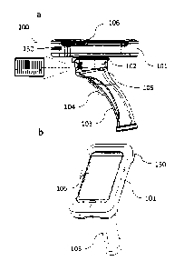
FIG. la is a side-view drawing of an embodiment of the mobile scanner gun
system docked through a base mount universal receiver with rotational coupling
to a
mobile tablet device operating in concert under the enterprise resource
planning mobile
application's environment;
5 FIG. lb is a top-side of the embodiment of FIG. la;
FIG. 2 is a schematic diagram illustrating the circuit of the Main PCB
residing
in the mobile tablet device upper receiver;
FIG. 3 is a schematic diagram illustrating an embodiment of the StoreMobile
Cloud TM environment of the subject system and method;
10 FIG. 4 is an in-depth schematic diagram illustrating an embodiment of
the
StoreMobile Cloud TM network schematic of the subject system and method;
FIG. 5 is a flow chart diagram illustrating an embodiment of the back room
management picture flow of the subject system and method;
FIG. 6 illustrates a side view of an embodiment of the subject mobile scanner
gun
15 system for processing a retail store purchase;
FIG. 7 illustrates a top view of the embodiment of FIG. 6;
FIG. 8 illustrates a cross-sectional view taken along cut-out of FIG. 6,
wherein
the mobile tablet device is removed from the pistol grip base housing;
FIG. 9a illustrates a top view of an embodiment of the frame / casing around a
20 mobile tablet device;
CA 02897909 2015-07-10
WO 2014/109937
PCT/US2014/000005
26
FIG. 9b illustrates a bottom view of the embodiment of the frame / casing
around a mobile tablet device of FIG. 9a;
FIG. 9c illustrates a side view;
FIG. 9d illustrates a bottom-side view;
FIG. 9e illustrates another bottom-side view;
FIG. 10 illustrates a top view of an embodiment of the frame / casing forming
around a mobile device;
FIG. 11 shows a cross-section view of the body of the pistol grip base housing
of FIG. 6;
FIG. 12 shows views of the body and trigger assembly of the mobile scanner gun
system;
FIG. 13 shows a side view of an embodiment of a pistol grip of the subject
mobile scanner gun system;
FIG. 14 shows a back view of an embodiment of the pistol grip of FIG. 13;
FIG. 15a-d illustrates the rotational mechanism of the subject mobile scanner
gun system;
FIG. 16 is a schematic diagram illustrating an embodiment of the Main PCB
circuit of the mobile scanner gun system;
FIG. 17 is a schematic diagram illustrating an embodiment of the sub-boards 1
and 2 circuitry of the mobile scanner gun system;
CA 02897909 2015-07-10
WO 2014/109937
PCT/US2014/000005
27
FIG. 18a illustrates a side elevation view of an embodiment of a mobile tablet
device interchangeable on an embodiment of the subject mobile scanner system,
shown
with the interface device-inserted therein;
FIG. 18b illustrates a back short side view of the device of FIG. 18a;
FIG. 18c illustrates a bottom view of the mobile tablet device of FIG. 18a;
FIG. 18d illustrates a side view of the mobile tablet device of FIG. 18a;
FIG. 19a illustrates a side elevation view of an embodiment of the subject
mobile scanner gun system adapted to receive a mobile tablet device thereon,
showing
the base mount universal receiver with a rotational coupler;
FIG. 19b illustrates a top back-side view of the mobile tablet device of FIG.
19a;
FIG. 19c illustrates a top back plane view of the mobile tablet device of FIG.
19a;
FIG. 19d illustrates a top front-side view of the mobile tablet device of FIG.
19a;
FIG. 20a illustrates a side elevation view of another embodiment of the
subject
mobile scanner gun system adapted to receive a mobile tablet device thereon,
showing a
modification add-on member - base mount universal receiver with rotational
coupler;
FIG. 20b illustrates a top back-side view of the mobile tablet device of FIG.
20a;
FIG. 20c illustrates a top back plane view of the mobile tablet device of FIG.
20a;
CA 02897909 2015-07-10
WO 2014/109937
PCT/US2014/000005
28
FIG. 20d illustrates a top front-side view of the mobile tablet device of FIG.
20a;
FIG. 20e illustrates a side view of the mobile tablet device of FIG. 20a;
FIG. 20f illustrates a front view of the mobile tablet device of FIG. 20a; and
FIG. 20g illustrates a back underside view of the mobile tablet device of FIG.
20a.
DETAILED DESCRIPTION OF THE INVENTION
This invention is directed towards a mobile scanner gun system adapted to
interchangeably receive and communicate with a mobile device, particularly a
mobile tablet
device, having a system integrated therein that enables store level real-time
inventory
management and a fully functioning POS capability for selling merchandise in a
retail sales
environment at any of a retailer's global locations. The mobile device,
including mobile tablet
device, has a display attached and is mounted to a pistol grip base housing
through a base
mount universal receiver with rotational coupling. The system comprises a
mobile tablet
device (upper receiver) having a display with the enterprise resource planning
mobile
application system software downloaded, which has an industry standard USB MSR
input
device integrated along the short edge of the mobile tablet device for easy
access by the user
regardless of which base housing is selected for use, in communication with
several base
housing concepts, each with a USB scanner input device integrated into the
base through the
specialized universal serial bus wiring harness. The system operates with the
mobile scanner
gun system and mobile tablet device thereon.
CA 02897909 2015-07-10
WO 2014/109937
PCT/US2014/000005
29
The mobile device, specifically mobile tablet device, is removably mounted on
the
mobile scanner gun system through a base mount universal receiver with
rotational coupling
and specialized universal serial bus wiring harness. The mobile tablet device
is capable of
being removed from the mobile scanner gun system and attached to other mobile
base housing
systems and docked on a fixed POS workstation and are constructed and
programmed to
operate under the same or interpretable operating system using the same mobile
software
applications. The mobile tablet device is preferably mounted through a base
mount universal
receiver with rotational coupling means that includes a sliding mechanism,
wherein the mobile
table slides onto the mount on the mobile scanner gun system. Most preferably,
the base mount
universal receiver with rotational coupling means that the mobile table can be
readily rotated on
the base from a vertical position (hereinafter, "portrait mode") to a
horizontal position
(hereinafter, "landscape mode") via 90 degree rotation on the horizontal
plane. Conversion
from portrait mode to landscape mode is achieved easily through the rotating
member without
operational delay of the system, and does not require disconnection from the
system. The
mobile tablet device frame can rotate 90 degrees either left or right from its
"home" portrait
position to its landscape position. Landscape and portrait "view" rotation of
the mobile tablet
device and mobile scanner gun system can be software locked based on current
active
position selected by the user.
Whether the specially constructed frame is utilized or the mobile tablet
device is
specially designed, the mobile tablet device is housed or integrated within a
rubberized frame
that encases the mobile tablet device body aside from the top touch screen.
The rubberized
CA 02897909 2015-07-10
WO 2014/109937
PCT/US2014/000005
frame is most preferably smooth and rugged to protect the mobile tablet device
in a hostile store
operation and provide optimal wear and usage as it is appointed to be used
throughout the day
on a sales floor. Further, a wrist lanyard is preferably connected at the base
of the mobile
scanner gun system to avoid unnecessary drops that could otherwise damage the
mobile scanner
5 gun system or the mobile tablet device.
The mobile tablet device is preferably measures about 2 inches to 10.5 inches
diagonally, preferably 4 inches to 7 inches, and most preferably 5 inches to
about 5.5 inches
diagonally. A specially designed and constructed mobile tablet device having
specific
mounting capability and durability features is preferably utilized with the
mobile tablet device
10 and system thereof. Though currently offered consumer grade mobile
tablets are contemplated
as well, however, the consumer grade tablets would require insertion within a
specially
constructed case or unit to enable mounting upon the mobile scanner gun
system. The
optionally constructed case includes a mounting slide adapted to mate with the
base mount
universal receiver with rotational coupling mechanism of the mobile scanner
gun system. The
15 case is constructed as a rubberized frame that removably receives and
houses the mobile tablet
device. In turn, download and integration of the operational system and mobile
software
applications would be required for operation of the subject system of the
mobile scanner gun
system.
A pistol handle construction is most preferred in the structure of the mobile
scanner gun
20 system for ergonomics, comfort and optimal handling of the mobile
scanner gun system as it is
adapted to be mobile throughout the store environment and thusly carried for
long periods of
CA 02897909 2015-07-10
WO 2014/109937
PCT/US2014/000005
31
time by an employee. Further, the pistol handle structure enables secure
carrying of the device
throughout the day inasmuch as the device is generally appointed to be carried
by the employee
or sales associate through the retailer's operation hours, as well as (hiring
inventory and
stocking events during non-operational hours. The scan gun trigger in turn, is
preferably
constructed as a pistol trigger design to further facilitate the functional
requirements of the
device's use in the retail environment for long hours and wear.
Further paramount to the intended functional long-term usages of the mobile
scanner
gun system is an extended battery life. Accordingly, the mobile scanner gun
system preferably
includes a battery system utilizing a battery that preferably resides within
the upper receiver of
the mobile tablet device. The mobile scanner gun system includes a micro USB
connector on
the bottom of the upper receiver for charging the primary mobile tablet device
and the
secondary battery located within the upper receiver housing of the mobile
scanner gun system.
The mobile scanner gun system includes a mobile tablet device upper receiver
that has a
specialized universal serial bus wiring harness which supports several USB
device interfaces,
such as mini USB and micro USB as are standard in consumer grade tablet
industry. The upper
receiver of the mobile scanner gun system is removable to allow the upper
receiver to be
mounted onto any of four base housing systems through its base mount universal
receiver with
rotational coupling. The construction of the mobile scanner gun system must be
hardened
plastic for durability and long usage hours. Additionally, the base mount
universal receiver and
rotational coupling connecting the mobile scanner gun system pistol grip base
housing to the
upper receiver is durable/industry hardened.
CA 02897909 2015-07-10
WO 2014/109937
PCT/US2014/000005
32
Fixed and integrated to the mobile scanner gun system pistol grip base
housing,
mounted directly above and in front of the trigger, is a USB scanner input
device. The scanner
has two drivers, including 1) a native device driver and 2) a keyboard input
driver. Fixed and
integrated along the short edge of the upper receiver of the mobile tablet
device and above the
scanner, is a USB MSR input device for use in carrying out POS sales
transactions requiring a
customer payment card. The MSR is networked with a certified bank card
processor and all
POS transactions are End to End Encrypted for PCI compliance requirements.
Additionally,
preferably the mobile tablet device is software secured through third party
security software and
rendered useless outside the retail enterprise as a theft deterrent.
Preferably, an RFID tag is
imbedded in the Tablet GunTM to sound an alarm if stolen.
The overall structure of the mobile scanner gun system is to make it look and
feel
"integrated" with the mobile tablet device and not as separate pieces and
parts. Even though
the mobile tablet device can be replaced and upgraded, the device has the look
and feel of one
tightly integrated device. Smooth edges and integrated design are utilized in
the structure for
comfort and durability. The entire system results in a rugged and tight system
and structure,
without looking like it is a "pieced together" device.
This invention relates to real-time daily store level inventory management and
a fully
functioning POS system for customer sales transactions of merchandise in a
retail sales
environment. The system comprises a mobile scanner gun system that has a
mobile tablet
device attached through a base mount universal receiver with rotational
coupling adapted to
permit changing the orientation of the tablet device in portrait mode or
landscape mode.
CA 02897909 2015-07-10
WO 2014/109937
PCT/US2014/000005
33
The system and method of the present invention provides technology that
empowers
sales associates to service their customers without consideration to the
physical location of the
product. Through use of the subject system and methods, goods can be purchased
anywhere,
anytime and delivered wherever and whenever the consumer wants it. Under
current systems
and methods, the consumer must travel to the location of the good (or order
the good on-line
through their personal device and wait for delivery or in store pick-up). This
adds an
inconvenient step - that is rather than allowing the sales associate to simply
handle the purchase
via a mobile POS device and have the item delivered where the customer wants,
the customer
must drive to the other location or place his / her own order through his /
her own means. Not
only is this inconvenient, but such inconvenience often results in the loss of
the sale altogether,
as the customer may decide to forego the purchase, or simply move on to the
competitor's store
if it is nearby and convenient to do so.
None of the heretofore systems and methods provide the ability for a retailer
to utilize
software and hardware that runs the entire store, ranging from real-time
inventory management,
to POS transactions. The system, method and devices herein provide this unique
advantageous
feature. The subject system and method, and devices implementing same, provide
the
following advantages: 1) increased store productivity, 2) reduced technology
cost and footprint,
and 3) improved customer satisfaction, all of which in turn ensures return on
investment (ROI).
ERP systems integrate internal and external management information throughout
an
organization, embracing finance/accounting, manufacturing, sales and service,
customer
relationship management, etc. ERP systems automate this activity with an
integrated software
CA 02897909 2015-07-10
WO 2014/109937
PCT/US2014/000005
34
application. The purpose of ERP is to facilitate the flow of information
between all business
functions inside the boundaries of the organization and manage the connections
to outside
stakeholders. ERP systems can run on a variety of computer hardware and
network
configurations, typically employing a database as a repository for
information. Examples of
vendors who build industry leading ERP systems include: JDA Software Group,
Oracle, SAP,
Epicor, etc. However, present systems do not provide the ability for a store
employee at a
physical store location to have direct mobile access to real-time inventory
management and
POS capability.
The subject system and methods provides real-time store level inventory
management
and mobile POS customer check-out to retail establishments that complement
current
merchandising systems generally utilized by chain retailers. Real-time mobile
inventory
management functionality is provided by the subject system and methods,
preferably built
around the JDA Merchandise Management System (MMS) environment, leveraging
current
legacy store systems and accessing the current MMS iSeries environment.
Through use of the
subject system MMS iSeries environment, businesses can build their own cloud
to provide
mobile customer check-out/order fulfillment and daily real-time inventory
management in the
store through the mobile scanner gun system.
Uniquely, the subject system and method provides the ability to use a mobile
tablet
device in a store to yield the following benefits: 1) it allows sales
associates to service
customers in new ways that deepen customer loyalty and increase wallet share;
2) it provides
inventory management for increased accuracy, efficiency, and accountability
while providing
CA 02897909 2015-07-10
WO 2014/109937
PCT/US2014/000005
real-time access to corporate inventory data; 3) it eliminates workflow in the
back office and
keeps the retailer's sales associates on the sales floor; and 4) it results in
higher customer
satisfaction. Implementation of the subject system and methods, and devices
thereon
implemented provides strong inventory management, and leveraging current
technology
5 infrastructure ensures ROT.
Advantageously, the subject system, method and devices of the present
invention allow
a sales associate using a mobile scanner device system anywhere in the store
and physically
beyond the store, to carry out inventory management tasks such as: a) Daily
Cycle Counting &
Physical Inventory, b) Receiving & Returns, c) Store Transfers, d) Item
Checking, e) Re-
10 Ticketing, etc. Such tasks are performed real time within the ERP system
and are all visible
chain-wide. Further, the sales associate can run mobile POS throughout the
sales floor and
beyond the stores physical walls, with all the capability previously contained
at the POS cash
wrap's fixed location. Through use of the subject system and method, a sales
associate can
perform the following from a mobile scanner gun system: i) sell "out of stock"
product
15 available in the warehouse, another store or from a vendor; ii) create a
purchase order (PO) or
transfer within MMS and track that item transfer on the web; iii) sell
products from their e-
commerce site; iv) combat "Showrooming" by providing customers real-time
competitive
product and pricing information, allowing staff to match prices and satisfy
their customer's
demands by exceeding expectations at the point of purchase.
20 Mobile POS represents the future of retail technology in chain retail.
For decades retail
stores have been designed around fixed cash-wrap POS stations / register
stations. New studies
CA 02897909 2015-07-10
WO 2014/109937
PCT/US2014/000005
36
indicate that cash-wrap POS stations / register stations are becoming less
relevant in future
retail markets. Approximately one fifth (21.4%) of retailers are planning on
removing or
decreasing use of traditional fixed-station POS / register stations per store.
Mobile POS will
eventually replace these systems. As mobile devices mature and harden the need
for POS
register stations, terminals and smart RF scan guns with cryptic processes
will continue to
dwindle.
However, today's enterprise mobile devices fall short; although many are
durable and
retail hardened, and work well for inventory, they are ineffective on sales
floor due to lack of
functionality and usability. Moreover, conventional enterprise mobile devices
are very
expensive and locked into outdated technology. Although consumer devices
appear to have
some potential to fill this gap, these devices lack durability, hardware
integration, and retail
specific software and functionality.
The system and method of the present invention provides implementation within
a
mobile scanner gun system that performs all the necessary real-time store
level inventory
management functions and utilize the Internet to provide competitive analysis,
thus determining
product pricing for the customer and transacting the sale accordingly. The
mobile scanner gun
system is totally mobile throughout the store and beyond its walls and does
not compromise
work-flow or require extensive training to use. The system, method, and
devices of the present
invention 1) match the exceptional "work flow" performance of legacy radio
frequency (RF)
data terminal for inventory management, 2) match the transaction speed of the
POS terminal
found in a high volume retail store, 3) are Payment Card Industry (PCI)
compliant, since
CA 02897909 2015-07-10
WO 2014/109937
PCT/US2014/000005
37
security is a necessary prerequisite in today's retail environment, and 4) are
durable, since the
store environment will challenge practically any piece of hardware.
An advantageous feature of the mobile scanner gun system and mobile tablet
device of
the invention is the simplicity of their design, which ensures that the final
product is both richly
functional and cost effective. The mobile tablet device (upper receiver) is
removable from the
mobile scanner gun system, is readily docked in other types of base scanner
housing platforms,
and is additionally capable of being docked in a fixed POS cash-wrap station.
By using
standard industry components such as industry standard USB MSR heads and
barcode scanner
components in conjunction with a preferably customized mobile tablet device,
the mobile
scanner system with mobile tablet device integration capability therein will
provide all the
standard features of a typical consumer grade tablet, coupled with retail
industry hardened
components integrated into an industry hardened frame ¨ built for industrial
use - with an "easy
to use" scan gun model, wearable model, hand held model and fixed workstation
model and
with the subject system and method readable therein. The functional
specification of the
mobile tablet device is a mini tablet that preferably measures about 2 inches
to 10.5 inches
diagonally, preferably 4 inches to 7 inches, and most preferably 5 inches to
about 5.5 inches
diagonally. The handle of the mobile scanner gun system is preferably coated
with rubber for
comfort and / or is enclosed within a comfort grip rubber covering and the
trigger is
ergonomically designed to be more like a pistol. Rotation from portrait mode
to landscape
mode of the mobile tablet device is achieved with compression tubes ¨ as
compression springs
roll in and out via a rotating dial ¨ the upper receiver rotates smoothly but
stays in place
CA 02897909 2015-07-10
WO 2014/109937
PCT/US2014/000005
38
through each fixed position. The mobile tablet device slides on and off from
the mobile
scanner gun system through communication of a button on one side of the mobile
tablet device,
sliding on and off via a groove slide. The USB input devices, including the
scanner and MSR,
of the mobile scanner gun system are powered by a rechargeable lithium ion
battery, as well as
a backup battery of equal size that extends battery life for a period of time
that is necessary to
assure uninterrupted operation on the sales floor.
A specialized universal serial bus wiring harness is used for charging the
lithium ion
battery system. Portability of the mobile scanner gun system's upper receiver
for the system
and method mobile tablet device implementation provides four base housing
concepts. The
mobile scanner gun system's upper receiver with integrated mobile tablet
device and MSR is
consistent for three of the four base housing concepts: 1) The mobile scanner
gun system 2) The
wearable mobile scanner system 3) The fixed docked workstation. The fourth
base housing
concept is the handheld housing and requires the scanner to be mounted
integrally into the
upper receiver along with the mobile tablet device and the MSR. Portability
makes the
system's tablet upper receiver even more valuable.
Generally stated, the present invention comprises a system and method for use
with a
mobile scanner gun system associated with an integration capable mobile tablet
device. This
system, method, mobile scanner gun system and integration capable mobile
tablet device is
used by an employee on a sales floor of a retail establishment for both daily
inventory
management purposes for such tasks as physical inventory, cycle counting,
inventory receiving,
store to store transfers, return to vendor, product re-ticketing and to
operatively identify a
CA 02897909 2015-07-10
WO 2014/109937
PCT/US2014/000005
39
product by its barcode, establish price, promotions, physical and electronic
coupons and
customer loyalty data and rewards available and process sale of product to a
customer
regardless of the location of the inventory. The sold inventory can be
transferred to any store
for customer pickup or shipped to a customer location from the mobile scanner
gun system.
Once the transaction is completed on the mobile scanner gun system, the sold
merchandise is
allocated and systemically visible within the ERP system chain-wide. With this
system, the
customer does not have to bring the merchandise to a central check out
location. In
conventional systems, the checkout procedure is typically carried out without
the customer
having adequate knowledge of the product, or comparing its features, price or
the like with
other competing products. Through use of the system and method implemented for
use with a
mobile scanner gun system and integration capable mobile tablet device, an
employee of a
retailer can sell merchandise from any store ¨ not only from within the
particular store's
inventory, but within any store or warehouse chain wide. The mobile scanner
gun system reads
the barcode of a particular item that is available for purchase, and retrieves
a plethora of
product details from the POS store systems server, using wireless
communication. Such details
may include current pricing, electronic or physical coupons, promotions, and
customer loyalty
data and rewards available, so that the retail sales employee on the floor can
communicate the
pricing structure to a potential customer anywhere on the sales floor. If the
customer decides to
purchase the item, the name of the customer as well as the customer's e-mail
address is
recorded if they are not already in the customer loyalty database, and the
payment card of the
customer is swiped through the MSR on the mobile scanner gun system. The
appropriate
CA 02897909 2015-07-10
WO 2014/109937
PCT/US2014/000005
encrypted payment card information is wirelessly transmitted via an encrypted
communication
to the POS store systems server within the store and onto a certified bank
card authorization
processor, whereby the encrypted authorization is returned to the POS store
systems server and
subsequently onto the mobile tablet gun system. Unless credit is denied, the
purchase is
5
authorized and the customer is given the purchased merchandise. The receipt
for this purchase
can be printed on the store network and / or sent by e-mail to the customer.
The POS store
systems server transmits the transaction details to the corporate ERP system
for adjustment of
inventory of merchandise that has been sold and those updates are available
real-time chain-
wide.
10
The mobile tablet device of the mobile scanner gun system preferably comprises
a
custom-developed, industry hardened device utilizing a specialized universal
serial bus wiring
harness to communicate with the USB input devices such as a barcode scanner
and an MSR.
Various operating systems, such as those associated with the trade name
Android, i0S, and
Windows are contemplated.
15
The mobile tablet device (upper receiver) is connected by a base mount
universal
receiver with rotational coupling adapted to permit changing the orientation
of the tablet device
in portrait mode or landscape mode of the tablet display screen and
communicate through a
specialized universal serial bus wiring harness with a barcode scanner input
device having a
system integrated therein, which is placed directly below the mobile tablet
device in the scan
20
gun model, integrated into the upper receiver in the hand held model,
integrated into the back of
the forehand in the wearable model, and fixed within the stand frame of the
workstation model.
CA 02897909 2015-07-10
WO 2014/109937
PCT/US2014/000005
41
There are a minimum of two standard USB input devices with others
contemplated: A barcode
scanner and an MSR. The MSR is positioned on the short edge of the mobile
tablet device
directly above the scanner in the scan gun model, which is forward facing on
the base of the
gun in front of the trigger. The scanner is connected to the mobile tablet
device using a
specialized universal serial bus wiring harness. The mobile tablet device has
custom
programmed applications in the IOS, Android and Windows platforms. Other USB
input
devices contemplated are a variety of mobile chip and pin payment card readers
that would
replace the MSR on the mobile scanner gun system upper receiver or connected
remotely using
Blue Tooth technology for communication between the mobile tablet device and
the mobile
chip and pin payment card reader.
Figures la and lb illustrate a first embodiment of the subject mobile scanner
gun system with integration of a mobile tablet device operational with the
system and
method, shown generally at 100. Figure la shows a side-view while Figure lb
shows a
top-side view of the device. The mobile scanner gun system is shown generally
at 100 in
Figures la and lb. Referring to Figs. la and lb, the mobile scanner gun system
100 has a
mobile tablet device 101 attached to the pistol grip base housing through the
base mount
universal receiver with rotational coupling 102, having a rotatable element
that permits the
alignment of the mobile tablet device in the portrait or landscape mode. The
figure shows the
mobile tablet device in the portrait mode. A plurality of applications is
present in the mobile
tablet device display screen 106. The pistol grip base housing has a gun
handle 103 with a
trigger 104, which turns on the barcode scanner 105. illumination from the
barcode scanner is
CA 02897909 2015-07-10
WO 2014/109937
PCT/US2014/000005
42
shown in Figure 1. Preferably, an MSR slot 150 for carrying-out payment card
transactions is
present on the short edge of the mobile tablet device 101. In landscape mode,
the MSR 150 is
perpendicular to the scanner; in portrait mode, the MSR 150 is parallel to the
scanner as shown
in Figure 1 a. The base mount universal receiver with rotational coupling 102
is connected to
the mobile tablet device through a slide groove mechanism 101 and is also not
visible in this
figure since it is incorporated within the rotatable connection between the
mobile tablet device
and the base mount universal receiver with rotational coupling (see Figures
hereinafter).
There are a number of specifically designed programmed applications that allow
the
mobile tablet device to command the USB input devices, such as the barcode
scanner and
MSR, through the specialized universal serial bus wiring harness to perform
various functions
typical to scanner operations and MSR operations. Running of the specially
programmed
mobile POS application, StoreMS MobileTM is initiated and a command is sent to
the EEPROM
to acquire a barcode scan. The mobile tablet device in this mode is ready to
receive the bamode
data from the scanner and communicates with the POS store systems server at
the retail facility
to obtain specific product information such as, product availability within
the store and chain,
price, promotions, physical and electronic coupons and customer loyalty data
and rewards
available. The employee of the retail organization presents the data that is
related to the
particular item of interest to the customer. When the customer decides to
purchase the
particular item scanned, the employee of the retail organization uses the
mobile POS
application to process the sales transaction, if needed for shipping,
pertinent customer
information is taken or their records are updated if they are already a
loyalty rewards customer.
CA 02897909 2015-07-10
WO 2014/109937
PCT/US2014/000005
43
At tender, the POS application can open the cash drawer wirelessly for cash
transactions and
also launch a request for processing the sale using a customer payment card.
The customer's
payment card is swiped via the MSR, which is located on the short edge of the
upper receiver.
All pertinent payment card data is encrypted by the MSR and the EEPROM
communicates the
encrypted data through the specialized universal serial bus wiring harness to
the mobile tablet
device.
The mobile POS application, StoreMS MobileTM, present in the mobile tablet
device
communicates all pertinent customer payment card data, using a PCI compliant
encrypted
wireless connection, to the POS store systems server. The POS store systems
server contacts a
PCI certified bank card processor to obtain authorization for the purchase. If
the purchase is
authorized, this information is sent to the mobile tablet device display
screen for customer
signature using an integrated signature capture application built within the
mobile POS
application on the mobile tablet device and the customer is allowed to take
possession of the
purchased merchandise. The POS store systems server can send a receipt for the
purchase to
the e-mail address and / or a hard copy of the receipt can also be printed in
a central printer
present in the retail establishment if desired. The POS store systems server
transmits the
transaction details to the corporate ERP system, updating inventory positions
of sold
merchandise and becoming visible chain-wide in real-time fashion. If the
credit purchase is
denied, the mobile tablet device displays this credit request decline. The
employee of the retail
organization informs the customer of this credit purchase rejection and
requests another form of
payment. Thus the purchase of a product by a customer is accomplished by
StoreMS MobileTM
CA 02897909 2015-07-10
WO 2014/109937
PCT/US2014/000005
44
by an employee having a mobile scanner gun system anywhere in the store, or
beyond the
physical location of the store, without the customer having to bring the
product to a sales
counter and wait in line at the counter to consummate the purchase; and the
inventory of any
item in the retail establishment is always current and available for purchase
transactions carried
out by a plurality of sales personnel working with a plurality of customers at
a wide variety of
locations within the retail establishment.
A key feature of the invention is an EEPROM that has a previously programmed
instruction set present within the Main PCB. The schematic diagram of the Main
PCB is
shown in Figure 2 at 200. The EEPROM is shown at 201 and is connected to the
mobile tablet
device at 202 and can process the command issued by the mobile applications to
command
either the barcode scanner or the MSR to acquire required data. The mobile
tablet device has
several mobile applications accessed by icons on the mobile tablet device
screen and has
functionality to communicate wirelessly via Wi-Fi or wireless cellular with a
POS store systems
server, a centrally located backup POS store systems server or directly to the
corporate ERP
system depending on the particular mobile application and function in use.
This
communication is secured using standard WPA or WPA2 wireless encryption
methods;
alternatively, a secondary means of communication is available through a
wireless cellular
module intergraded into the mobile tablet device and accessed via a data plan
through a
standard cellular carrier. When the payment card transaction is approved by
the bank card
authorization processor, the appropriate encrypted payment card information is
wirelessly
transmitted via an encrypted communication back to the POS store systems
server within the
CA 02897909 2015-07-10
WO 2014/109937
PCT/US2014/000005
store and onto the mobile scanner gun system, whereby the encrypted
authorization is processed
by the mobile POS application. Unless credit is denied, the transaction
authorization is sent to
the mobile tablet device display screen for customer signature using an
integrated signature
capture application built within the mobile POS application on the mobile
tablet device and the
5 customer is given the purchased merchandise. The receipt for this
purchase can be printed on
the store network and / or sent by e-mail to the customer. The POS store
systems server sends a
request to the ERP system to update appropriate allocated inventory for
merchandise sold
regardless of the fulfillment location used to complete the purchase. The ERP
system processes
that request and updates the corporate inventory databases, which are
accessible chain-wide.
10 Due to the use of the EEPROM, which can process barcode and payment
card
information, the attached mobile tablet device can perform secure distributed
sales within a
retail establishment. Through StoreMS MobileTM, all store employees know
instantaneously
the available inventory of any particular item across the chain; any product
and its particular
details can be reviewed with the customer and sold regardless of the products
availability in the
15 store ringing the sale. Thus a customer may look at a variety of
products and ask the sales
person its price, detailed product description, as well as any physical and
electronic coupons,
promotions and customer loyalty data and rewards that are available. This
provides a friendly,
efficient and informative interaction between the customer and the retail
salesperson; it
establishes a one-on-one face-to-face relationship, which is appreciated by
the customer and is
20 conducive to an improved sales environment.
CA 02897909 2015-07-10
WO 2014/109937
PCT/US2014/000005
46
Figure 3 is a schematic diagram illustrating an embodiment of the StoreMobile
Cloud TM environment of the subject system and method. Figure 4 is an in-depth
schematic diagram illustrating an embodiment of the StoreMobile Cloud TM
environment of the subject system and method. Figure 5 is a flow chart diagram
illustrating an embodiment of the back room management picture flow of the
subject
system and method. Referring generally to Figures 3-5, generally a three-
phased approach
is implemented by the subject system and method.
In phase I of building the StoreMobile CloudTM environment, the corporate ERP
inventory management applications relating to the store are mobilized through
the subject
system's StoreMobileRFTm, a trademark of Retail Technologies Corporation,
application. As a
result of the system's StoreMobileRFTm application, retailers can manage store
inventory in
real-time fashion, connected directly to their corporate ERP system from a
mobile scanner gun
system in any store.
In phase II of building the StoreMobile CloudTM environment, POS and related
store
systems are fully operational so that POS customer check-out is mobilized
through its StoreMS
MobileTM application. The system's StoreMS MobileTM application works
alongside the
system's StoreMobileRF TM. Access to the Internet, StoreMS Loyalty TM, StoreMS
Gift Card
TM, and end to end encrypted payment card processing are standard features of
the mobile
scanner gun system's StoreMS MobileTM application. Advantageously, StoreMS
MobileTM
excels at "line busting", reducing overall store register count, or completely
replacing all fixed
POS cash wrap stations throughout the store.
CA 02897909 2015-07-10
WO 2014/109937
PCT/US2014/000005
47
In Phase III of building the StoreMobile Cloud TM environment, StoreMobileRFTm
and
StoreMS MobileTM applications are both up and running together, with StoreMS
MobileTM
directly accessing the POS store systems server and StoreMobileRFTm directly
accesses the
corporate ERP system. Additionally, StoreMS Mobile can now access the
corporate ERP
system for pertinent inventory availability throughout the chain and sell,
transfer, and special
order merchandise not available in its own store through the corporate ERP
system. Further,
the allocation of inventory for these special POS transactions is visible
chain-wide through the
StoreMobileRFTm application.
Figure 6 illustrates a side view of an embodiment of the subject mobile
scanner
gun system for processing a retail store purchase, shown generally at 1000.
Figure 7
illustrates a top view of the embodiment of FIG. 6. Referring to Figures 6 and
7, the
mobile scanner gun system 1000 comprises a main body portion 2000 extending
toward a
handle portion 1001. Main body portion 2000 includes handle portion 1001, a
base 1004, side
walls 1005, a front wall 1006 and a back wall 1007 constructed to form an
interior cavity 1008.
Front wall 1006 includes an aperture 1009 with a lens 1010 recessed therein.
The front wall
1006 has a trigger member 1020 located near the base 1004 of the main body. A
scanner device
1030 is mounted above and in front of the trigger 1020. The scanner includes a
scanner engine
and has two drivers, including 1) a native device driver and 2) a keyboard
input driver, the
scanner device being in communication with the trigger for initiating a scan
of a barcode.
An MSR device 1050 is integrated within the device for carrying out and
processing
customer sales transactions. Preferably, the MSR device 1050 is located along
the side of the
CA 02897909 2015-07-10
WO 2014/109937
PCT/US2014/000005
48
mobile tablet device in the upper receiver directly above the scanner 1030.
The MSR device is
end-to-end encrypted for PCI security compliance requirements. The MSR 1050
allows for
direct POS customer transaction processing anywhere wherein Wi-Fi or wireless
cellular
connectivity is available, thus not limited to the retail sale floor but
anywhere Wi-Fi or wireless
cellular service is available for inventory on the floor, locale warehouse,
tent sales, or globally
throughout the retailer's enterprise. A very unique feature of the subject
system and device
thereof is the ability to go beyond the store with the wireless cellular
connectivity. Top wall
1004' of base 1004 of the main body portion includes an attachment means 1060.
Attachment
means 1060 comprises a base mount universal receiver with rotational coupling
and specialized
universal serial bus wiring harness 1062 adapted to interchangeably mount and
communicate
with a mobile device 2000 having a system integrated therein that enables
store level real-time
inventory management and a fully functioning POS capability for selling
merchandise in a retail
sales environment and global inventory management. The base mount universal
receiver with a
rotational coupling means 1061 (shown as a sliding track) includes a rotating
member 1065 for
conversion of the mobile tablet device from portrait mode to landscape mode
without
operational delay of the system. (See Fig. 15a-d for images of an embodiment
of the rotating
member).
Figure 8 illustrates a cross-sectional view taken along cut-out XX of Figure
6,
shown generally at Figure la-105. In the illustration shown, the mobile tablet
device
2000 is removed from the gun 1001 for view of the top wail 1004' of base 1004
of the
main body portion includes an attachment means 1060. Attachment means 1060
comprises a
CA 02897909 2015-07-10
WO 2014/109937
PCT/US2014/000005
49
base mount universal receiver with rotational coupling means 1061 and
specialized universal
serial bus wiring harness 1062 adapted to intemhangeably mount and communicate
with a
mobile device 2000 having a system integrated therein that enables store level
real-time
inventory management and a fully functioning POS capability for selling
merchandise in a retail
sales environment and global inventory management. The base mount universal
receiver with a
rotational coupling means 1061 includes a rotating member 1065 for conversion
of the mobile
device from portrait mode to landscape mode without operational delay of the
system.
Figures 9a-9e illustrates views of and construction of the frame / casing for
the
mobile device. Particularly: Figure 9a illustrates a top view of an embodiment
of the
frame / casing around a mobile device; Figure 9b illustrates a bottom view of
an
embodiment of the frame / casing around a mobile device; Figure 9c illustrates
a side
view; Figure 9d illustrates a bottom-side view; and Figure 9e illustrates
another
bottom-side view.
Referring to Figures 9a-9e, the mobile device is shown generally at 13000 and
is
preferably a mobile tablet device. The mobile tablet device 13000 includes a
display screen
13001, preferably being a touch screen. The mobile tablet device 13000 is
received and house
within a case assembly 13020, and is preferably a customized mobile tablet
device 13000, but it
is contemplated that the device may be a currently offered device that fits
within the case
assembly 13020. Preferably the device 13000 can be removed from case assembly
13020, by
use of the upper receiver release button 13030, as needed for
interchangeability and
replacement, or for docking at a fixed POS workstation. . Preferably, case
assembly 13020 is
CA 02897909 2015-07-10
WO 2014/109937
PCT/US2014/000005
constructed having a rubberized frame, or otherwise sturdy durable material.
The case
assembly 13020 is preferably smooth and rugged to protect the mobile tablet
device 13000 in a
hostile store operation and provide optimal wear and usage as it is appointed
to be used
throughout the day on a sales floor, warehouse or the like.
5
Generally, case assembly 13020 is constructed having a front cover 13021 that
is
formed as a frame, and includes a screen cut-out 13022, mounted on a bottom
cover 13046
thereby substantially encasing the mobile tablet device 13000 (for a
representative in-depth
construction of the case assembly, see Figure 10 and the discussion herein
relating to same).
An MSR slot 13033 is integrated within case assembly 13020 for alignment with
an MSR
10
within case assembly 13020. A specialized universal serial bus wiring harness
connector for
communication and engaging the base mount universal receiver when the mobile
tablet device
13000 is mounted on the pistol grip base housing shown at 13041. A quick
release sliding
mechanism 13048 (preferably being a tongue adapted to a receiver groove as a
means to secure
the mobile tablet device to the base device) is integrated within the bottom
cover 13046.
15
Figure 10 illustrates a top view of an embodiment of the frame / casing
forming
around a mobile tablet device, shown generally at 3000. Referring to Figure
10, a case
assembly 3020 is provided for receiving a mobile device 3000, preferably a
customized mobile
tablet device. Preferably the mobile device can be removed from case assembly
3020 as needed
for interchangeability and replacement, or for docking at a fixed POS
workstation. Preferably,
20
case assembly 3020 is constructed having a rubberized frame, or otherwise
sturdy durable
material. The case assembly 3020 is preferably smooth and rugged to protect
the mobile tablet
CA 02897909 2015-07-10
WO 2014/109937
PCT/US2014/000005
51
device 3000 in a hostile store operation and provide optimal wear and usage as
it is appointed
to be used throughout the day on a sales floor, warehouse or the like.
Case assembly 3020 is constructed having a front cover 3021 that is formed as
a frame,
and includes a screen cut-out 3022 and MSR LED light guide 3023, that sits on
a rubber boot
3024 casement which in turn encases the side walls of the mobile tablet device
3000. An over-
molded internal chassis 3030 is provided for receiving the mobile tablet
device 3000. Over-
molded internal chassis 3030 is preferably composed of a PC substrate rubber
over mold, and
includes a volume button 3031, LED for MSR 3032, MSR 3033, power button 3034,
and
battery/charging indicator light guide 3035 cut-outs and parts assemblies. A
Main PCB with
connectors and DC jack 3041' is provided within a main board 3040, which is
located directly
under and mounted to the over-molded internal chassis 3030. An internal
battery 3043 is
provided, along with a sub-board 1 shown at 3045 for signal and power
connections to the
mobile scanner gun system, bottom cover assembly 3046 having a pocket for
scanner buzzer
3047 and a quick release sliding mechanism 3048 (preferably being a tongue
adapted to a
receiver groove as a means to secure the mobile tablet device to the base
device). Preferably,
internal battery 3043 is a heavy duty component capable of powering operation
of the mobile
scanner gun system throughout substantially the entire shift; preferably for a
time period
ranging from 10 to 18 hours, and more preferably for a time period ranging
from 12 to 16 hours
Figures 11 and 12 show the cross-section view of the body of the gun of Figure
6, and assembly thereof, respectively. A main body portion 4002 extending
toward a
handle portion 4003 is provided. Main body portion 4002 includes handle
portion 4003, a base
CA 02897909 2015-07-10
WO 2014/109937
PCT/US2014/000005
52
4004, side walls 4005, a front wall 4006 and a back wall 4007 constructed to
form an interior
cavity 4008. Front wall 4006 includes an aperture 4009 with a lens 4009' for a
scanner device
4030 and engine recessed therein. The front wall 4006 has a trigger member
4020 located near
the base 4004 of the main body. Scanner device 4030 is mounted above and in
front of the
trigger 4020.
Figure 13 shows a side view of an embodiment of a pistol grip of the subject
mobile scanner gun system ¨ which may be formed as a rubber / silicone cover.
Figure
14 shows a back view of an embodiment of the pistol grip of FIG. 13.
Figures 15a-d illustrates the rotational mechanism of the subject mobile
scanner
gun, shown generally at 5001. In the embodiment shown, a main body 5002
includes a
spring plunger assembly, indicated generally at 5003 including detents 5004
used for fixed
rotational interval positioning.
Figure 16 is a schematic diagram illustrating an embodiment of the Main PCB
circuit of the mobile scanner gun, shown generally at 6000. Main PCB 6001 is
shown.
Main PCB 6001 includes a battery 6002, Magtek MSR head 6003, USB to mobile
tablet device 6004, USB to PC 6005, 5A DC jack 6006, Battery LED 6007, MSR LED
6008 (preferably via 3 pins) and connection to sub-board at 6009.
Figure 17 is a schematic diagram illustrating an embodiment of the sub-boards
1
and 2 circuitry of the mobile scanner gun system, shown generally at 7000. Sub
board 1
is shown generally at 7001. Sub board 1 includes a specialized universal
serial bus
wiring harness for MSR 7002 and scanner / trigger (16 pin) 7003, and terminal
7004
CA 02897909 2015-07-10
WO 2014/109937
PCT/US2014/000005
53
(preferably 18 pins) with sub board 3 on SG (switch) and sub board 4 on PG
(switch).
Sub board 2 is shown generally at 7020. Sub board 2 includes a main PCB 7021
and
Opticon scanner 7022.
Figure 18a illustrates a side elevation view of an embodiment of a mobile
tablet
device interchangeable on the subject mobile scanner gun system, shown with
the
interface device inserted therein, shown generally at 1500. Figures 18b-d
illustrates views of
the embodiment of Figure 18a. Specifically, Figures 18b illustrates a back
short side view,
Figure 18c illustrates a bottom view, and Figure 18d illustrates a side view.
Referring to Figures 18a-18d, a mobile tablet device is received / housed
within a
case assembly shown at 1520. Case assembly 1520 is constructed having a front
cover that is
formed as a frame, and includes a screen cut-out and features as discussed
herein. A main PCB
with connectors /DC jack is provided 1541, located directly under and mounted
to the over-
molded internal chassis. Signal and power connection to the mobile scanner
system is provided
through interface device 1550. A quick release sliding mechanism 1548 is
provided, preferably
being a tongue adapted to receive groove of the interface device 1550, which
in turn is adapted
to be secured on the mobile scanner system. In the embodiment shown, a main
body includes a
spring plunger assembly, indicated generally at including detents used for
interval rotational
positioning and friction plates to assist in rotational stability and overall
durability.
Figures 19a-19d illustrates views of an embodiment of the subject mobile
scanner gun system, adapted to receive a mobile tablet device thereon, showing
the
pistol grip base housing at 1900. Figures 19a illustrates a side view, Figure
19b illustrates
CA 02897909 2015-07-10
WO 2014/109937
PCT/US2014/000005
54
a top back-side view, Figure 19c illustrates a top back plane view, and Figure
19d
illustrates a top front-side view. Pistol grip base housing 1901 comprises a
main body
portion 1902 extending toward a handle portion 1903. Main body portion 1902
includes handle
portion 1903, a base 1904, side walls 1905, a front wall 1906 and a back wall
1907 constructed
to form an interior cavity. Front wall 1906 includes an aperture with a lens
1910 recessed
therein. The front wall 1906 has a trigger member 1920 located near the base
1904 of the main
body. A scanner 1930 is mounted above and in front of the trigger 1920. The
scanner includes
a scanner engine and has two drivers, including 1) a native device driver and
2) a keyboard
input driver, the scanner device being in communication with the trigger for
initiating a scan of
a barcode.
Top wall 1904' of base 1904 of the main body portion includes an attachment
means
1960. Attachment means 1960 comprises a base mount universal receiver with
rotating
coupling means 1961 and a specialized universal serial bus wiring harness
connector 1962
adapted to interchangeably mount and communicate with a mobile tablet device
having a
system integrated therein that enables store level real-time inventory
management and a fully
functioning mobile POS capability for selling merchandise in a retail sales
environment and
real-time store level inventory management. The attachment means 1960 includes
a rotating
member (not shown) for conversion of the mobile device from portrait mode to
landscape mode
without operational delay of the system.
Referring to Figure 16, the USB MSR input device software is integrated within
the
Main PCB for carrying out and processing sales transactions. Referring to
Figures la-lb,
CA 02897909 2015-07-10
WO 2014/109937
PCT/US2014/000005
preferably, the MSR itself is located directly above the scanner on the short
side of the mobile
tablet device upper receiver and is in communication through the EEPROM 6003.
Figures 20a-20g illustrate views of another embodiment of the subject mobile
scanner
gun system adapted to receive a mobile tablet device thereon, showing a
modification
5 add-on member and the pistol grip base housing, indicated generally at
2000. Referring
to Figures 20a-20g, the pistol grip base housing 2001 comprises a main body
portion 2002
extending toward a handle portion 2003. Main body portion 2002 includes handle
portion
2003, a base 2004, side walls 2005, a front wall 2006 and a back wall 2007.
Front wall 2006
includes an aperture with a lens 2010 recessed therein mounted in front of the
scanner (Fig 6
10 1030), located within the base 2004 of the main body portion 2002. The
scanner includes a
scanner engine and has two drivers, including 1) a native device driver and 2)
a keyboard input
driver, the scanner device being in communication with the trigger for
initiating a scan of a bar
code. The front wall 2006 has a trigger member 2020.
Base 2004 includes modification add-on members 2070 and 2070' located thereon
a top
15 wall 2004'. Modification add-on members 2070 and 2070' and visa vie top
wall 2004' of base
2004 of the main body portion includes an attachment means 2060. Attachment
means 2060
comprises a base mount universal receiver with rotational coupling base means
2061 and
specialized universal serial bus wiring harness connector to the upper
receiver 2062 adapted to
interchangeably mount and communicate with a mobile tablet device having a
system
20 integrated therein that enables store level real-time inventory
management and a fully
functioning POS capability for selling merchandise in a retail sales
environment. The
CA 02897909 2015-07-10
WO 2014/109937
PCT/US2014/000005
56
attachment means 2060 includes a rotating member (not shown) for conversion of
the mobile
device from portrait mode to landscape mode without operational delay of the
system.
Referring to Figure 20E an MSR device 2050 is integrated within the mobile
tablet device 2100
and is in communication through the specialized universal serial bus wiring
harness connector
2062 shown on figure 20c, for processing POS transactions.
Modification add-on member 2070 is adapted to provide a supplemental base
support
for mounting and securing the mobile tablet device 2100 on the scanner gun
2001 (see Figures
20e-20h for views including the mobile tablet device mounted thereon).
Modification add-on
member 2070 extends outwardly on the horizontal plane and adjacent from base
2004 to form a
shelf 2070' running substantially parallel to the side walls 2005 of handle
2003. Preferably,
modification add-on member 2070 further includes a front shelf 2070' adjacent
to and under the
base mount universal receiver with rotational coupling 2060 shown in Figure
20c. Having thus
described the invention in rather full detail, it will be understood that such
detail need not be
strictly adhered to, but that additional changes and modifications may suggest
themselves to
one skilled in the art, all falling within the scope of the invention as
defined by the subjoined
claims.