Note: Descriptions are shown in the official language in which they were submitted.
CA 02897916 2015-07-10
WO 2014/110400
PCT/US2014/011086
Fl I I __ ING FOR JOINING TUBES AND METHOD OF JOINING TUBES
Cross-Reference to Related Applications
[0001]This application claims the benefit of the filing date of provisional
patent
application Serial No. 61/751,613, filed January 11,2013, which is currently
pending.
Statement Regarding Federally Sponsored Research or Development
[0002,]Not Applicable.
Appendix
[0003 ]Not Applicable.
BACKGROUND OF THE INVENTION
Field of the Invention
[00043This invention pertains to fittings for joining pressurized tubes to
each other.
More particularly, the present invention pertains to metal crimp fittings that
are
configured to create metal-to-metal seals that can maintain a pressure seal at
temperatures that exceed the working temperatures of most polymeric 0-rings.
CA 02897916 2015-07-10
WO 2014/110400
PCT/US2014/011086
General Background
[0005]As discussed in U.S. Patent Application Serial No. 13/714,002, filed
December 13, 2012 (which, in its entirety, is hereby incorporated into the
present
application by reference), metal crimp fittings can be used to join metal
tubes
together in a manner such that the joints are leak free at gauge pressures in
excess
of 2000, psi (13.8 MPa). Such fittings are particularly suited for use in
connection
with HVAC plumbing, However, such crimp fittings often rely on the use of 0-
rings
or other types of sealing elements that are not capable of resisting high
temperatures. Thus, such fittings are not well suited for use in connection
with OXY-
MED plumbing that are required to withstand a pressure of 300 psi (2.07 MPa)
after
experiencing temperatures in excess of 1,000 F (538 C). At such
temperatures,
polymeric materials melt and/or become ineffective at maintaining pressure
seals.
[00063 OXY-MEDplumbing is typically required to operate at maximum pressures
of
less than 100 psi (0.69 MPa). However, because OXY-MED lines contain
pressurized oxygen, the building codes and specifications require such lines
to be
capable of withstanding the high temperatures associated with minor fires.
Additionally, because at least some of such oxygen is ultimately inhaled,
there are
typically strict requirements related to the cleanliness of the tubing and
joints used in
OXY-MED plumbing. Thus, the fittings and tubing used must be formed out of
materials that can be cleaned and that do not pose any health risks, and that
can
withstand an oxygen rich environment. Often, the tubes used in OXY-MED
plumbing
are hard drawn copper and the joints or other fittings are soldered or brazed.
While
conventional soldering/brazing techniques can be used to join some of such
tubes
2
CA 02897916 2015-07-10
WO 2014/110400
PCT/US2014/011086
(copper tubes in particular), soldering or brazing can have disadvantages. For
example, soldering/brazing typically involves the use of a torch, which
creates an
inherent fire risk during installation. This can be problematic or prohibited
in
situations where tubes need to be joined in buildings while such buildings are
open
to the public. In addition, a protective gas must be charged into the
connection
before brazing to prevent oxidization of the interior surfaces and
contamination of the
OXY-MED plumbing lines.
SUMMARY OF THE INVENTION
[0007 ]The present invention allows tubes to be connected to each other using
a
crimping technique rather than a soldering or brazing technique. Moreover, the
fittings in accordance with the present invention utilize metal-to-metal seals
that are
capable of maintaining pressure seals at pressures in excess of 300 psi (2.07
MPa)
and withstanding temperatures in excess of 1000 F (538 C.). That being said,
the
fittings, although particularly suited for use in connecting OXY-MED tubes,
can also
be useful in connecting other types of plumbing such as water lines. The
fittings are
preferably annealed and used to join hardened tubes.
[00081 in one aspect of the invention, a crimp fitting comprises a monolithic
and
homogeneous female socket that is configured to receive and be crimped to an
end
portion of a tube. The socket comprises an annular wall and an axial opening.
The
annular wall comprises an inner cylindrical surface portion and at least one
annular
sealing portion that protrudes radially inward from axially adjacent portions
of the
annular wall. The cylindrical surface portion lies axially between the opening
and the
CA 02897916 2015-07-10
WO 2014/110400
PCT/US2014/011086
annular sealing portion, and has a diameter matched to the OD of the tube to
which
the fitting is configured to connect. The annular sealing portion has an
innermost
diameter that is greater than the diameter of the cylindrical surface portion.
In view
of this geometry, as the end of the tube is inserted into the socket, the tube
cannot
slideably contact the annular sealing portion. Thus, the annular sealing
portion will
not be damaged by the insertion of the end of the tube. Thereafter, the
annular
sealing portion is radially crimped inwards and ultimately contacts and
deforms a
portion of the tube in a manner creating interlocking geometry and a pressure
seal.
[00093 In another aspect of the invention, a crimp fitting comprises a
monolithic and
homogeneous female socket that is configured to receive and be crimped to an
end
portion of a tube. The socket comprises an annular wall and an axial opening.
The
annular wall comprises an inner cylindrical surface portion and an axially
serrated
inner surface portion. The cylindrical surface portion lies axially between
the
opening and the axially serrated inner surface portion. The axially serrated
inner
surface forms a plurality of annular sealing portion protrusions.
(00103 Yet another aspect of the invention pertains to a method of crimping a
monolithic and homogeneous female socket portion of a crimp fitting to an end
portion of a tube. The socket portion comprises an annular wall and an axial
opening. The annular wall comprises an inner cylindrical surface portion and
at least
one annular sealing portion. The cylindrical surface portion lies axially
between the
opening and the annular sealing portion, and has a diameter matched to the OD
of
the tube to which the fitting is configured to connect. The annular sealing
portion has
an inward facing surface that has an innermost diameter that is initially
greater than
4
CA 02897916 2015-07-10
WO 2014/110400
PCT/US2014/011086
the diameter of the cylindrical surface portion. The method comprises
inserting
the end portion of the tube into the socket portion of the crimp fitting
through the axial
opening of the socket portion. In view of fact that the end portion of the
tube has a
diameter that is approximately equal to the diameter of the inner cylindrical
surface
portion of the socket portion, the end portion of the tube is coaxial to the
cylindrical
surface portion and passes through the annular sealing portion without
contacting
the annular sealing portion. The method thereafter comprises crimping the
socket
portion of the crimp fitting in a manner such that the innermost diameter of
the
annular sealing portion reduces and the annular sealing portion contacts the
end
portion of the tube, thereby creating a permanent necked-in region in the end
portion
of the tube. The crimping also occurs in a manner such that, when the crimping
is
completed, the necked-in region in the end portion of the tube and the annular
sealing portion of the socket portion remain radially compressed against each
other.
(00113Further features and advantages of the present invention, as well as the
operation of the invention, are described in detail below with reference to
the
accompanying drawings.
BRIEF DESCRIPTION OF THE DRAWINGS
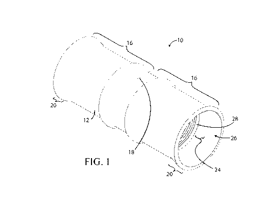
[0012]Figure 1 is a perspective view of a fitting in accordance with the
invention,
which is configured to join two equal diameter tubes to each other.
[0013]Figure 2 is a top view of the fitting shown in Figure 1.
(0014]Figure 3 is a cross-sectional view of the fitting shown in Figures 1 and
2,
taken about the line 3-3 of Figure 2.
CA 02897916 2015-07-10
WO 2014/110400
PCT/US2014/011086
[0015] Figure 4 is a detail view of Figure 3.
(001671Figure 5 is a perspective view showing two tubes inserted into the
fitting
shown in Figures 1-4,
(0017]Figure 6 is a cross-sectional view of the assembly shown in Figure 5.
(0018]Figure 7 is a cross-sectional view depicting the assembly shown in
Figures 5
and 6 after the fitting has been crimped.
(0019:1Reference numerals in the written specification and in the drawing
figures
indicate corresponding items.
DETAILED DESCRIPTION
1.0020]A crimp fitting in accordance with the invention is shown in Figures 1-
4, The
crimp fitting 10 shown is of the type that is configured to join two equal
diameter
tubes to each other. However, it should be appreciated that other fittings in
accordance with the invention could also be configured to join two or more
tubes of
differing diameters, or could be an integral portion of the end of a tube that
is
configured to receive the end of another tube. Thus, the invention is not
limited to
the particular embodiment of the invention shown in the figures.
[0021] The fitting 10 is primarily formed via a single monolithic annular wall
12, but
may also comprise one or more brazing rings 14 configured to melt when the
fitting
is subjected to fire, or one or more 0-rings made of a material which can
withstand
temperatures up to 1000 F (538 C) without losing elasticity. The annular
wall 12 of
the fitting 10 forms a female socket 16 in each of its axially opposite
halves. The
annular wall 12 is preferably formed from a section of cylindrical copper-
alloy tubing.
6
CA 02897916 2015-07-10
WO 2014/110400
PCT/US2014/011086
A dimple insertion stop 18 is preferably press-formed into the top and bottom
of
annular wall 12 of the fitting 10 at its plane of axial symmetry. Each female
socket
16 preferably comprises a flare 20 and a brazing ring channel 22 formed into
the
annular wall 12 of the fitting 12. The flare 20 extends from a cylindrical
portion 24 of
the respective socket 16 and flares radially outward as it extends to the
opening 26
of the socket. The brazing ring channel 22 and the flare 20 are preferably
formed
using a hydroforming technique. One or more annular sealing protrusions 28 are
formed on the inner surface of the annular wall 12, preferably between the
brazing
ring channel 22 and the cylindrical portion 24 of each socket 16. The annual
sealing
protrusions 28 are preferably formed by cutting grooves into portions of the
annular
wall 12 between the sealing protrusions, and preferably each socket 16
comprises a
series of such sealing protrusions that form an axially serrated portion 30
within each
socket. The grooves may be semi-circular, V-shaped, or square, or any other
shape
desired. Additionally, rather than forming a series of sealing protrusions 28
that are
transverse to the center axis of the fitting 10, axially serrated portion 30
within each
socket 16 could be formed by cutting a helical groove into the annular wall 12
(thereby forming a helical sealing protrusion). The depth of the grooves is
preferably
in the range of 0.010 and 0.015 inches (approximately 0.25 to 0.38 mm). The
annular wall 12 of the fitting 10 is preferably annealed to a soft temper with
a grain
size between 0.005 mm and 0.070 mm,
[0022]As is noticeable in Figure 4, each of the annular sealing protrusions 28
of the
serrated portion 30 of each socket 16 has an innermost diameter that is
slightly
greater than the adjacent cylindrical portion 24 of the socket. This ensures
that, as
7
CA 02897916 2015-07-10
WO 2014/110400
PCT/US2014/011086
the end portion of a tube 32 is inserted into the socket 16 (as shown in
Figures 5 and
6), the tube does not contact the sealing protrusions. Of course, that is
because the
cylindrical portion 24 has a diameter that fits snugly around the end portion
of the
tube 32. As such, the sealing protrusions 28 cannot be damaged by the
insertion of
the end portion of the tube 32. Prior to inserting the end portion of the tube
32 into
one of the sockets 16, the grooves between sealing protrusions 28 of that
socket are
preferably filled with a high temperature sealant (not shown), such as
Superior Seal
& Assist # 5000 produced by Superior Industries. Shortly thereafter, the end
portion
of the tube 32 is inserted into said the socket 16. Upon contacting the dimple
insertion stops 18, the end portion of the tube 32 is fully inserted into the
fitting 10
and the female socket 16 can then be crimped. The crimping process is
preferably
performed in a generally uniform manner, as is described in U.S. Patent
Application
Serial No. 13/714,002. The radially outward extending bulge created by the
formation of the brazing ring channel 22 and the flare 20 of the female socket
16
preferably serve as guides between which the crimper straddles the fitting 10
during
the crimping process. This ensures that the crimper is axially located in the
most
ideal location along the female fitting 16. Preferably the crimper only crimps
the
annular wall 12 in the region of the sealing protrusion 28 or serrated portion
30 of the
female fitting 16. As this occurs, the soft (annealed) sealing protrusion(s)
28 radially
conforms against the end portion of the hard tube 32 and a corresponding
portion 34
of the end portion of the tube 32 necks-in as shown in Figure 7.
Simultaneously, the
crimping also causes the sealant to flow out of the grooves between the
sealing
protrusions 28 and into the spaces radially between the sealing protrusions
and the
8
CA 02897916 2015-07-10
WO 2014/110400
PCT/US2014/011086
end portion of the tube 32. The crimping also causes the crimped portion of
the
annular wall 12 to work harden. Because the fitting 10 is initially annealed
and work
hardens during the crimping process and the end portion of the tube 32 is
fully hard,
after crimping, the necked-in portion 34 of the end portion of the tube 32
will remain
radially biased against the sealing protrusion(s) 28 with a radial compression
force
that creates a pressure seal sufficient to withstand a pressure differential
in excess
of 300 psi (2.07 MPa). It should also be appreciated that the crimping creates
interlocking geometry between the fitting 10 and the end portion of the tube
32 that
prevents the end portion of the tube 32 from thereafter pulling axially out of
the
fitting. Still further, it should be appreciated that the sealant is
configured to remain
liquid or pliable when at high temperatures in a manner such that the sealant
will not
crack should the fitting axially expand in a fire. Thus, the sealant provides
additional
sealing capability in the event of fire.
[0023]As mentioned above, a brazing ring 14 can also be positioned in the
respective brazing ring channel 22 prior to inserting the end portion of the
tube 32
into the respective female socket 16 of the fitting 10. The purpose of the
brazing ring
14 is not to be brazed when forming the joint between the fitting 10 and the
end
portion of the tube 32. Instead, the brazing ring 14 acts as a backup sealing
means
in the event the joint is subjected to fire or other abnormally high
temperatures.
When the joint is subjected to such fire or other abnormally high
temperatures, the
brazing ring 14 will melt and form an additional barrier to gas leaks. An
alternative
to brazing rings 14 are the high temperature 0-rings discussed above. If such
high
temperature 0-rings are used, a crimping tool may be configured to apply
lesser
9
CA 02897916 2015-07-10
WO 2014/110400
PCT/US2014/011086
compressive forces onto exterior portions of the annular wall 12 that encircle
the
channels 22 during the process of crimping the fitting 10. Doing so would
increase
the compression of the 0-rings and improve the effectiveness of the 0-rings.
However, like the brazing rings 14, the purpose of the 0-rings would be to
provide
backup sealing means in the event the joint is subjected to fire or other
abnormally
high temperatures. In either case, the crimping process is preferably
performed in a
generally uniform manner, as is described in U.S. Patent Application Serial
No.
13/714,002.
[0024] In view of the foregoing, it should be appreciated that the invention
achieves
the several advantages over prior art fittings,
[0025]As various modifications could be made in the constructions and methods
herein described and illustrated without departing from the scope of the
invention, it
is intended that all matter contained in the foregoing description or shown in
the
accompanying drawings shall be interpreted as illustrative rather than
limiting. Thus,
the breadth and scope of the present invention should not be limited by any of
the
above-described exemplary embodiments, but should be defined only in
accordance
with the following claims appended hereto and their equivalents.
[0026]It should also be understood that when introducing elements of the
present
invention in the claims or in the above description of exemplary embodiments
of the
invention, the terms "comprising," "including," and "having" are intended to
be open-
ended and mean that there may be additional elements other than the listed
elements. Additionally, the term "portion" should be construed as meaning some
or
all of the item or element that it qualifies. Moreover, use of identifiers
such as first,
CA 02897916 2015-07-10
WO 2014/110400
PCT/US2014/011086
second, and third should not be construed in a manner imposing any relative
position
or time sequence between limitations. Still further, the order in which the
steps of
any method claim that follows are presented should not be construed in a
manner
limiting the order in which such steps must be performed.
11