Note: Descriptions are shown in the official language in which they were submitted.
CA 02898426 2015-07-16
I.
1
GEAR MACHINING APPARATUS
TECHNICAL FIELD
[0001]
The present invention relates to a gear machining apparatus that shapes a
gear by machining a workpiece with a grinding wheel, and a gear machining
method for the same.
BACKGROUND ART
[0002]
As described in Patent Document 1, an apparatus is conventionally
known that shapes a gear by causing a hob to rotate at a high speed and then
by
gear cutting a workpiece with cutting teeth of the hob.
Furthermore, as a gear machining apparatus that shapes a gear by
grinding a workpiece with a grinding wheel, an apparatus is known that shapes
a gear by dressing a threaded grinding wheel with a dresser having a shape
corresponding to a shape of the gear to be machined and then by causing the
threaded grinding wheel to grind the workpiece into a shape corresponding to
the shape of the dresser.
CITATION LIST
Patent Literature
[0003]
Patent Document 1: Japanese Unexamined Patent Application Publication No.
2010-125571A
SUMMARY OF INVENTION
Technical Problem
[0004]
However, in the above-described conventional gear machining apparatus,
when the threaded grinding wheel grinds the workpiece while rotating with the
workpiece in a meshed state, the threaded grinding wheel grinds the workpiece
in a tooth trace direction of a tooth surface of the gear. Thus, the surface
uniformity in the tooth trace direction of the tooth surface of the gear can
be
ground favorably.
[0005]
With regard to such a gear machining apparatus, the present inventors
have conducted diligent research to improve the accuracy of grinding the tooth
CA 02898426 2015-07-16
=
2
surface of the gear. In the course of the research, the present inventors have
identified a problem in which, when the gear is shaped by machining the
workpiece with the threaded grinding wheel, a tooth surface slip rate, at
which
the threaded grinding wheel moves with respect to the workpiece in a tooth
profile direction, becomes zero at a reference pitch circle diameter at the
time
of grinding, and as a result, the surface uniformity in a tooth profile
evaluation
range of the tooth surface of the gear is decreased.
[0006]
In light of the foregoing, an object of the present invention is to provide
a gear machining apparatus and a gear machining method with which the
surface uniformity in a tooth profile evaluation range of a tooth surface of a
gear can be improved.
Solution To Problem
[0007]
To solve the abovementioned object, an embodiment of the present
invention is a gear machining apparatus configured to shape a gear by
machining a workpiece with a grinding wheel. The gear machining apparatus
comprises a threaded grinding wheel configured to shape a gear by machining a
workpiece and a disc-shaped dresser configured to shape the threaded grinding
wheel while rotating with the threaded grinding wheel in a meshed state. A
pressure angle of the dresser is designed to be shifted (dislocated) so that a
position, at which relative movement in a tooth profile direction of the gear
does not occur between a surface of the threaded grinding wheel and a gear to
be machined, is positioned outside of a tooth profile evaluation range, when
the
shaped threaded grinding wheel shapes the gear. The tooth profile evaluation
range is set as a section of a tooth surface of the machined gear that
functions
as a tooth surface of the gear when the gear is used.
In the present invention configured in this manner, the dresser shapes
the threaded grinding wheel, and the threaded grinding wheel shapes the gear
by machining the workpiece. When the shaped threaded grinding wheel shapes
the gear, the pressure angle of the dresser is designed to be shifted so that
the
position, at which relative movement in the tooth profile direction of the
gear
does not occur between the surface of the threaded grinding wheel and the gear
to be machined, is positioned outside of the tooth profile evaluation range.
As
a result, within the tooth profile evaluation range of the tooth surface of
the
machined gear, the position does not exist at which relative movement in the
tooth profile direction of the gear does not occur between the surface of the
CA 02898426 2015-07-16
3
threaded grinding wheel and the gear to be machined. Thus, a tooth surface
slip rate, at which the threaded grinding wheel moves with respect to the
workpiece in the tooth profile direction of the workpiece, does not become
zero,
and it is possible to improve the surface uniformity in the tooth profile
evaluation range of the tooth surface of the gear.
[0008]
In the present invention, preferably, the dresser is designed to be shifted
so that the pressure angle thereof is decreased, and the position at which
relative movement does not occur is moved to an inner side of the tooth
profile
evaluation range.
In the present invention configured in this manner, the dresser is
designed to be shifted so that the pressure angle thereof is decreased, and
the
position, at which relative movement in the tooth profile direction of the
gear
does not occur between the surface of the threaded grinding wheel and the gear
to be machined, is moved to the inner side of the tooth profile evaluation
range
of the tooth surface. Thus, the position at which relative movement does not
occur does not exist within the tooth profile evaluation range of the tooth
surface of the gear. As a result, a value of the tooth surface slip rate, at
which
the threaded grinding wheel moves with respect to the workpiece in the tooth
profile direction of the workpiece, does not become zero, and it is possible
to
improve the surface uniformity in the tooth profile evaluation range of the
tooth surface of the gear.
[0009]
In the present invention, preferably, the dresser is designed to be shifted
so that the pressure angle thereof is increased, and the position at which
relative movement does not occur is moved to an outer side of the tooth
profile
evaluation range of the tooth surface.
In the present invention configured in this manner, the dresser is
designed to be shifted so that the pressure angle thereof is increased, and
the
position, at which relative movement in the tooth profile direction of the
gear
does not occur between the surface of the threaded grinding wheel and the gear
to be machined, is moved to the outer side of the tooth profile evaluation
range
of the tooth surface. Thus, the position at which relative movement does not
occur does not exist within the tooth profile evaluation range of the tooth
surface of the gear. As a result, the value of the tooth surface slip rate, at
which the threaded grinding wheel moves with respect to the workpiece in the
tooth profile direction of the workpiece, does not become zero, and it is
CA 02898426 2016-11-10
52440-27
4
possible to improve the surface uniformity in the tooth profile evaluation
range of the tooth
surface of the gear.
[0010]
In the present invention, preferably, a gear machining method for shaping a
gear by machining a workpiece with a grinding wheel includes the steps of
preparing a
threaded grinding wheel configured to shape a gear by machining a workpiece
and a disc-
shaped dresser configured to shape the threaded grinding wheel while rotating
with the
threaded grinding wheel in a meshed state, wherein a pressure angle of the
dresser is designed
to be shifted so that a position, at which relative movement in a tooth
profile direction of the
gear does not occur between a surface of the threaded grinding wheel and a
gear to be
machined, is positioned outside of a tooth profile evaluation range, when the
shaped threaded
grinding wheel shapes the gear; shaping the threaded grinding wheel with the
dresser; and
shaping the gear by machining the workpiece with the threaded grinding wheel,
wherein the
tooth profile evaluation range is set as a section of a tooth surface of the
machined gear that
functions as a tooth surface of the gear when the gear is used.
In the present invention configured in this manner, the dresser shapes the
threaded grinding wheel, and the threaded grinding wheel shapes the gear by
machining the
workpiece. When the shaped threaded grinding wheel shapes the gear, the
pressure angle of
the dresser is designed to be shifted so that the position, at which relative
movement in the
tooth profile direction of the gear does not occur between the surface of the
threaded grinding
wheel and the gear to be machined, is outside of the tooth profile evaluation
range of the tooth
surface. As a result, within the tooth profile evaluation range of the tooth
surface of the
machined gear, the position does not exist at which relative movement in the
tooth profile
direction of the gear does not occur between the surface of the threaded
grinding wheel and
the gear to be machined. Thus, a tooth surface slip rate, at which the
threaded grinding wheel
moves with respect to the workpiece in the tooth profile direction of the
workpiece, does not
become zero, and it is possible to improve surface uniformity in the tooth
profile evaluation
range of the tooth surface of the gear.
CA 02898426 2016-11-10
52440-27
4a
[0010a]
According to an embodiment, there is provided a gear machining apparatus
comprising: a threaded grinding wheel configured to shape a gear by machining
a workpiece;
and a disc-shaped dresser configured to shape the threaded grinding wheel
while rotating with
the threaded grinding wheel in a meshed state, wherein a pressure angle of the
disc-shaped
dresser is shifted so that a position, at which relative movement in a tooth
profile direction of
the gear does not occur between a surface of the threaded grinding wheel and a
gear to be
machined, is positioned outside of a tooth profile evaluation range, when the
threaded
grinding wheel shapes the gear, and wherein the tooth profile evaluation range
is set as a
section of a tooth surface of the machined gear that functions as a tooth
surface of the gear
when the gear is used.
[0010b]
According to another embodiment, there is provided a gear machining method
comprising the steps of: preparing a threaded grinding wheel configured to
shape a gear by
machining a workpiece and a disc-shaped dresser configured to shape the
threaded grinding
wheel while rotating with the threaded grinding wheel in a meshed state;
shaping the threaded
grinding wheel with the disc-shaped dresser; and shaping the gear by machining
the
workpiece with the threaded grinding wheel, wherein a pressure angle of the
disc-shaped
dresser is shifted so that a position, at which relative movement in a tooth
profile direction of
the gear does not occur between a surface of the threaded grinding wheel and a
gear to be
machined, is positioned outside of a tooth profile evaluation range, when the
threaded
grinding wheel shapes the gear, and wherein the tooth profile evaluation range
is set as a
section of a tooth surface of the machined gear that functions as a tooth
surface of the gear
when the gear is used.
Advantageous Effects of Invention
[0011]
According to a gear machining apparatus and a gear machining method of the
present invention, it is possible to improve the surface uniformity in a tooth
profile evaluation
range of a tooth surface of a gear.
CA 02898426 2015-07-16
Brief Description of Drawings
[0012]
FIG. lA is a plan view schematically illustrating tooth surface slip that
5 occurs when a conventional threaded grinding wheel moves with respect to
a
workpiece in a tooth profile direction of a gear, wherein FIG. lA illustrates
a
state before a reference pitch circle diameter portion of the gear of the
workpiece and a reference pitch circle diameter corresponding portion of the
threaded grinding wheel come into contact with each other in a relationship at
the time of grinding.
FIG. 1B is a plan view schematically illustrating tooth surface slip, in
which the conventional threaded grinding wheel moves with respect to the
workpiece in the tooth profile direction of the gear, wherein FIG. 1B
illustrates
a state in which the abovementioned portions are in contact with each other.
FIG. IC is a plan view schematically illustrating tooth surface slip, in
which the conventional threaded grinding wheel moves with respect to the
workpiece in the tooth profile direction of the gear, wherein FIG. 1C
illustrates
a state after the abovementioned portions have come into contact with each
other.
FIG. 2 is a diagram illustrating a tooth profile direction, a tooth trace
direction, and a tooth profile evaluation range on a tooth surface of the
gear.
FIG. 3 is a perspective view illustrating a gear machining apparatus
according to an embodiment of the present invention.
FIG. 4 is a front view illustrating the gear machining apparatus
according to the embodiment of the present invention.
FIG 5 is a plan view illustrating the gear machining apparatus according
to the embodiment of the present invention.
FIG. 6 is a schematic plan view illustrating a positional relationship
between a threaded grinding wheel and a dresser device of the gear machining
apparatus of the present invention.
FIG. 7 is a schematic perspective view illustrating a state in which the
threaded grinding wheel of the gear machining apparatus according to the
embodiment of the present invention grinds the workpiece.
FIG. 8 is a line chart comparatively showing tooth surface slip rates, in
the tooth profile evaluation range, of respective tooth surfaces of a gear
shaped
by a first embodiment of the present invention and a gear shaped by a
conventional apparatus.
CA 02898426 2015-07-16
6
FIG. 9 is a line chart showing the surface uniformity, in the tooth profile
evaluation range, of the tooth surface of the gear shaped by the gear
machining
apparatus according to the first embodiment of the present invention.
FIG. 10 is a line chart showing the surface uniformity, in the tooth
profile evaluation range, of the tooth surface of the gear shaped by the
conventional apparatus.
FIG. 11 is a line chart comparatively showing tooth surface slip rates, in
the tooth profile evaluation range, of respective tooth surfaces of a gear
shaped
by a second embodiment of the present invention and the gear shaped by the
conventional apparatus.
Description of Embodiments
[0013]
As described above, the present inventors, et al. have identified a
problem in which, when a gear is shaped by machining a workpiece with a
threaded grinding wheel, a tooth surface slip rate, at which the threaded
grinding wheel moves with respect to the workpiece in a tooth profile
direction,
becomes zero, and as a result, the surface uniformity in a tooth profile
evaluation range of a tooth surface of the gear deteriorates. This problem
will
be described with reference to FIGS. 1A, 1B, and 1C.
[0014]
As illustrated in FIGS. 1A, 1B, 1C and FIG. 2, when a threaded grinding
wheel 100 grinds a workpiece 102, a tooth surface slip phenomenon (tooth
surface slip) occurs in which the threaded grinding wheel 100 moves with
respect to the workpiece 102 in a tooth profile direction A of a tooth surface
102f while slipping.
FIG. lA illustrates a state before a reference pitch circle diameter
portion of a gear of a workpiece and a reference pitch circle diameter
corresponding portion of the threaded grinding wheel come into contact with
each other in a conventional grinding process. FIG. 1B illustrates a state in
which the reference pitch circle diameter portion and the reference pitch
circle
diameter corresponding portion are in contact with each other, and FIG. 1C
illustrates a state after both the reference pitch circle diameter portion and
the
reference pitch circle diameter corresponding portion have come into contact
with each other. FIG. 2 is a diagram illustrating a tooth profile direction, a
tooth trace direction, and a tooth profile evaluation range on a tooth surface
of
the gear.
[0015]
CA 02898426 2015-07-16
7
Here, as illustrated in FIG. 2, the tooth profile direction A of the
workpiece (gear) indicates a direction from a tooth tip of a tooth of the
workpiece (gear) toward a root of the tooth (or a direction from the root of
the
tooth toward the tooth tip), and a tooth trace direction B indicates a
direction in
which a tooth trace of the tooth of the workpiece (gear) extends. Furthermore,
in FIG. 1, a reference pitch circle diameter PCD is illustrated by a virtual
line.
Note that the tooth profile direction A, the tooth trace direction B, and the
tooth
profile evaluation range on the tooth surface of the gear are illustrated in
FIG. 2,
and the tooth profile direction A, the tooth trace direction B, and the tooth
profile evaluation range on the tooth surface of the gear illustrated in FIG.
2 are
also referred to with similar meanings in an explanation of the present
invention given below.
[0016]
As illustrated in FIG. 1A, the threaded grinding wheel 100, which has a
thread ridge formed in a helical pattern on an outer peripheral surface
thereof,
is rotated about a central rotation axis in a direction of an arrow D, and a
thread
ridge 100a on the outer peripheral surface of the threaded grinding wheel 100
moves in a direction of an arrow E.
With the threaded grinding wheel 100 and the workpiece 102 in a
meshed state, when the thread ridge 100a of the threaded grinding wheel 100
moves in the direction of the arrow E, the workpiece 102 is rotated about the
rotation axis in a direction of an arrow F. At this time, as the thread ridge
100a
of the threaded grinding wheel 100 and an external tooth 102a of the workpiece
102 are moving relatively to each other so that a part of the thread ridge
100a
comes into contact with a part of the external tooth 102a, the thread ridge
100a
of the threaded grinding wheel 100 grinds the external tooth 102a of the
workpiece 102 in the tooth profile direction A.
[0017]
In FIG. 1A, the reference pitch circle diameter PCD of the gear 102 is
illustrated by a reference pitch circle diameter 102b, and a point on the
reference pitch circle diameter PCD on the surface of the external tooth 102a
of
the workpiece102 is illustrated by a reference pitch circle diameter portion
102c. Furthermore, in the threaded grinding wheel 100, a section on the
surface of the thread ridge 100a of the threaded grinding wheel 100 which
corresponds to the reference pitch circle diameter PCD of the gear 102, is
illustrated by a reference pitch circle diameter corresponding portion 100b.
[0018]
CA 02898426 2015-07-16
8
As illustrated in FIG. IA, the reference pitch circle diameter portion
102c is positioned so as to be separated from the reference pitch circle
diameter
corresponding portion 100b, and an external tooth surface tooth tip portion
102d and a thread ridge surface tooth root portion 100c are in a state of
being
in contact with each other. After that, as the thread ridge 100a moves in the
direction of the arrow E and the workpiece 102 rotates in the direction of the
arrow F, grinding is performed while a section that extends from the thread
ridge surface tooth root portion 100c further to the tooth root side than the
reference pitch circle diameter corresponding portion 100b sequentially makes
contact with a section that extends from the external tooth surface tooth tip
portion 102d further to the tooth tip side than the reference pitch circle
diameter portion 102c, so as to perform tooth surface slip (so as to move in
the
tooth profile direction A while slipping).
Thus, a value of a rate at which tooth surface slip of the workpiece 102
is performed by the section that extends from the thread ridge surface tooth
root portion 100c of the threaded grinding wheel 100 to the reference pitch
circle diameter corresponding portion 100b, with respect to the section that
extends from the external tooth surface tooth tip portion 102d of the
workpiece
102 further to the tooth tip side than the reference pitch circle diameter
portion
102c, (a rate of movement in the tooth profile direction A) becomes greater
than zero. In this way, as the tooth surface slip rate has a value greater
than
zero, the threaded grinding wheel grinds, slipping in the tooth profile
direction
A of the workpiece 102, and thereby, the surface uniformity of the tooth
surface
102f of the machined gear 102 becomes favorable.
[0019]
Next, as illustrated in FIG 1B, the thread ridge 100a moves in the
direction of the arrow E, and the workpiece 102 rotates in the direction of
the
arrow F. As a result, the external tooth surface tooth tip portion 102d of the
external tooth 102a of the workpiece 102 moves relatively in a direction
toward
a tooth bottom 100d, which is formed between the thread ridges 100a of the
threaded grinding wheel 100, and the reference pitch circle diameter
corresponding portion 100b and the reference pitch circle diameter portion
102c come into contact with each other so as to be aligned with each other.
Specifically, the reference pitch circle diameter corresponding portion 100b
and
the reference pitch circle diameter portion 102c match up with each other
without performing tooth surface slip (movement in the tooth profile direction
A) with respect to the workpiece 102. Thus, the rate at which tooth surface
slip
CA 02898426 2015-07-16
9
is performed by the threaded grinding wheel 100 with respect to the workpiece
102 (the rate of movement in the tooth profile direction A) becomes zero.
In this state, at the reference pitch circle diameter portion 102c, in the
relationship at the time of grinding between the threaded grinding wheel 100
and the gear 102, the threaded grinding wheel 100 does not move with respect
to the workpiece 102 in the tooth profile direction A of the workpiece 102.
Thus, at the reference pitch circle diameter portion 102c, the machined gear
is
only ground in the tooth trace direction B, and not in the tooth profile
direction
A. As a result, the surface uniformity at the reference pitch circle diameter
portion 102c becomes non-uniform. In a conventional gear grinding process,
the reference pitch circle diameter portion 102c, in the relationship at the
time
of grinding between the threaded grinding wheel 100 and the gear 102, matches
up with the reference pitch circle diameter portion when the machined gear is
operated. Therefore, when the gear is operated, as the reference pitch circle
diameter portion 102c with a non-uniform surface uniformity is used as a
meshing surface, performance of the gear deteriorates.
[0020]
After that, as illustrated in FIG. 1C, the thread ridge 100a of the threaded
grinding wheel 100 moves in the direction of the arrow E, and the workpiece
102 rotates in the direction of the arrow F. As a result, the external tooth
surface tooth tip portion 102d is moved relatively so as to be separated
further
from the tooth bottom 100d, and the reference pitch circle diameter portion
102c is moved to a position separated from the reference pitch circle diameter
corresponding portion 100b.
At that time, as the thread ridge 100a moves in the direction of the arrow
E and the workpiece 102 rotates in the direction of the arrow F, grinding is
performed while a section that extends from the reference pitch circle
diameter
corresponding portion 100b to a thread ridge surface tooth tip portion 100e
sequentially makes contact with a section that extends from the reference
pitch
circle diameter portion 102c to an external tooth surface tooth root portion
102e, so as to perform tooth surface slip (so as to move in the tooth profile
direction A while slipping). Thus, the value of the rate at which tooth
surface
slip of the workpiece 102 is performed by the section that extends from the
reference pitch circle diameter corresponding portion 100b of the threaded
grinding wheel 100 to the thread ridge surface tooth tip portion 100e, with
respect to the section that extends from the reference pitch circle diameter
portion 102c of the gear 102 to the external tooth surface tooth root portion
102e, (the rate of movement in the tooth profile direction A) becomes greater
CA 02898426 2015-07-16
than zero. Thus, the value of the rate at which tooth surface slip is
performed
by the threaded grinding wheel 100 with respect to the workpiece 102 becomes
a value greater than zero. Therefore, the threaded grinding wheel 100 can
grind
in the tooth profile direction A of the workpiece 102 while slipping, and
thereby,
5 the surface uniformity of the tooth surface 102f of the gear 102 becomes
favorable.
As described above, in the conventional gear machining process,
slipping does not occur between the threaded grinding wheel and the workpiece
in the tooth profile direction A at the reference pitch circle diameter
portion
10 102c in the relationship at the time of grinding between the workpiece
and the
threaded grinding wheel (FIG. 1B). The present inventors have identified a
problem in which, due to the above, the surface uniformity of the tooth
surface
at the reference pitch circle diameter portion 102c deteriorates, and as a
result
of this section being used as the meshing surface when the gear is operated,
the
performance of the gear deteriorates. In the present invention, the threaded
grinding wheel is designed to be shifted so that the reference pitch circle
diameter, in the relationship at the time of grinding between the workpiece
and
the threaded grinding wheel, becomes different from the reference pitch circle
diameter when the machined gear is operated (the reference pitch circle
diameter when the machined gear is meshed with another gear when the
machined gear is used). As a result, the reference pitch circle diameter
portion
at the time of grinding, on which the surface uniformity deteriorates, can be
moved outside the tooth profile evaluation range when gears are meshed in
operation, and thus it is possible to prevent deterioration of the gear
performance.
[0021]
With reference to the attached drawings, embodiments of a gear
machining apparatus according to the present invention which have solved the
problem of the conventional apparatus described above will be described below.
First, with reference to FIG. 3 to FIG. 6, a basic structure of a gear
machining apparatus according to a present embodiment will be described.
The reference sign 1 denotes a gear machining apparatus, and the gear
machining apparatus 1 has a bed 2 that is provided at a base portion of the
gear
machining apparatus 1. In a description to be made below, a long-side
direction of a top surface of the bed 2 is referred to as an x-axis direction,
a
short-side direction thereon is referred to as a y-axis direction, and a
direction
orthogonal to the top surface of the bed 2 is referred to as a z-axis
direction.
CA 02898426 2015-07-16
11
On the top surface of the bed 2, a work holding portion 6 is provided, which
is
used to hold a workpiece (gear) 4 (work) that is the gear to be ground.
[0022]
The work holding portion 6 has a cylindrical table 8 attached to the top
surface of the bed 2. The table 8 is arranged so that a center axis of the
cylindrical shape thereof extends in the z-axis direction.
Furthermore, the work holding portion 6 has a cylindrical work
machining rotating shaft 10 that passes through the inner circumference of the
table 8. The work machining rotating shaft 10 is supported by a bearing
provided in the inner circumference of the table 8 so as to be able to rotate
about an axis line Cl extending in the z-axis direction.
Furthermore, the work holding portion 6 has a work rotating device 12
that is used to move the workpiece (gear) 4 between a work replacement
position, at which a machined gear 4 is replaced with a non-machined
workpiece 4 and the workpiece 4 is attached to the work holding portion 6, and
a work machining position, at which the workpiece 4 is ground with the
threaded grinding wheel.
[0023]
The work rotating device 12 is provided with a rectangular column-
shaped fixed portion 14 that is fixed to the top surface of the bed 2 and a
rectangular column-shaped rotating portion 16 that is rotatably supported by
the fixed portion 14.
A rotating portion 16 can rotate about an axis line C2 extending in the z-
axis direction. A pair of tailstocks 18 are provided on the sides of the
rotating
portion 16. The pair of tailstocks 18 are arranged at positions axially
symmetric to each other with respect to the axis line C2. Furthermore, the
tailstocks 18 are supported on the sides of the rotating portion 16 so as to
be
able to slide in the z-axis direction.
A work arbor 20, which is used to support and rotate the workpiece
(gear) 4, is attached to each of the tailstocks 18. The work arbor 20 has a
round
bar-shape and extends downward from a lower end of the tailstock 18 in the z-
axis direction. The work arbor 20 is supported by a bearing provided in the
interior of the tailstock 18 so as to be able to rotate about a rotation axis
line
C3 of a long-side direction of the work arbor 20.
[0024]
The workpiece (gear) 4 is held in a leading end portion of the work
arbor 20. In the work machining position, a rotation axis line C7 of the work
arbor 20 of one of the tailstocks 18 is aligned with the axis line Cl of the
work
CA 02898426 2015-07-16
12
machining rotating shaft 10, and the workpiece (gear) 4 is clamped by the
leading end portion of the work arbor 20 and a leading end portion of the work
machining rotating shaft 10. In this way, when the work arbor 20 of one of the
tailstocks 18 is in the work machining position, the work arbor 20 of the
other
tailstock 18 is in the work replacement position. When the work arbor 20 of
one of the tailstocks 18 moves from the work machining position to the work
replacement position, the work arbor 20 of the other tailstock 18 is caused to
move from the work replacement position to the work machining position.
[0025]
Furthermore, a grinding wheel holding portion 22, which is used to hold
the grinding wheel, is provided on the top surface of the bed 2 at a position
facing the work holding portion 6.
The grinding wheel holding portion 22 is provided with a rectangular
column-shaped column 24 that is provided on the top surface of the bed 2 at a
position facing the work holding portion 6. The column 24 is provided so as to
be able to move on the top surface of the bed 2 in the x-axis direction.
Of the side surfaces of the column 24, a saddle 26 is provided on the
side surface facing the work holding portion 6. The saddle 26 is provided on
the side surface of the column 24 so as to be able to slide in the z-axis
direction
and to rotate about an axis line C4 extending in the x-axis direction.
A grinding wheel head 28, which is used to support and rotate the
grinding wheel, is provided on the saddle 26.
The grinding wheel head 28 is supported on the side surface of the
saddle 26 so as to be able to slide along an axis line C5 that is orthogonal
to the
x-axis. Furthermore, the grinding wheel head 28 is provided with a grinding
wheel rotating shaft 30 that extends along the axis line C5. The grinding
wheel
rotating shaft 30 rotates about the axis line C5 using a driving force of a
motor
provided in the grinding wheel head 28. A cylindrical threaded grinding wheel
32, which has a thread ridge formed in a helical pattern on an outer
peripheral
surface thereof, is detachably attached to a tip of the grinding wheel
rotating
shaft 30. In a state in which the threaded grinding wheel 32 is attached to
the
grinding wheel rotating shaft 30 of the grinding wheel head 28, a rotation
axis
line of the threaded grinding wheel 32 is aligned with the axis line C5.
[0026]
The threaded grinding wheel 32 has the thread ridge formed in a helical
pattern on the outer peripheral surface thereof, and the shape of the thread
ridge
is a shape corresponding to desired gear parameters (desired parameters of a
finished and completed machined gear, which include modules, pressure angles,
CA 02898426 2015-07-16
13
the number of teeth, helix angles, and the like) of the gear (work) which is
the
subject workpiece. As described below, the shape of the thread ridge is a
shape
formed by a dresser 36 that shapes the threaded grinding wheel 32.
[0027]
Furthermore, as illustrated in FIG. 6, the gear machining apparatus 1 is
provided with a dresser device 34 that is provided on the bed 2 and that
shapes
the threaded grinding wheel 32 (the dresser device 34 is omitted in FIG. 3 to
FIG. 5). Positional relationships between the dresser device 34 and the
threaded grinding wheel 32, the axis line C2 of the rotating portion 16 of the
work rotating device 12, and the like are illustrated in FIG. 6. The dresser
device 34 is a rotary dressing device that shapes the threaded grinding wheel
32.
The dresser device 34 is provided with the dresser 36, to which a diamond is
attached so as to be able to shape the threaded grinding wheel 32 and which is
formed in a disc-shape, and a dresser holding portion 38 that can drive the
dresser 36 to rotate and hold the dresser 36. Here, the shaping operation
includes trueing operations and dressing operations of the threaded grinding
wheel 32 by the dresser 36.
The dresser holding portion 38 is provided on the bed 2 and can rotate
about the axis line C2 of the rotating portion 16 of the work rotating device
12.
The dresser holding portion 38 can cause the dresser 36 to move to a position
facing the threaded grinding wheel 32 and to be arranged at a position at
which
the threaded grinding wheel 32 is shaped. The dresser holding portion 38 can
support the dresser 36 while rotating the dresser 36 about a rotation axis
line
C6.
[0028]
The dresser 36 shapes the threaded grinding wheel 32 in accordance
with its own shape, and the shape of the workpiece 4 is ground in accordance
with the shape of the threaded grinding wheel 32. Thus, the shape of the
dresser 36 corresponds to the shape of the gear 4. For example, the dresser 36
has a type of relationship in which, when a pressure angle a of the dresser 36
is
determined, a pressure angle of the threaded grinding wheel 32, which is
shaped by the dresser 36, is also determined. In this way, when gear
parameters of the dresser 36, such as the pressure angle a, and the like, are
determined, the dresser 36 can indirectly determine gear parameters of the
gear
4, such as the pressure angle, and the like, via gear parameters of the
threaded
grinding wheel 32, such as the pressure angle and the like. Specifically, the
gear parameters of the dresser 36 are designed in accordance with a desired
tooth profile of the gear 4.
CA 02898426 2015-07-16
14
In this way, when the parameters of the dresser 36 are designed to be
shifted, the reference pitch circle diameter PCD, in the relationship between
the
threaded grinding wheel 32 and the gear 4 to be machined, may be moved by
this via the threaded grinding wheel 32. Specifically, as a result of the
dresser
36 being designed to be shifted, the position at which relative movement in
the
tooth profile direction does not occur between a surface of the threaded
grinding wheel 32 and the gear 4 to be machined may be moved. Parameters of
the dresser 36 being designed to be shifted means that the parameters of the
dresser 36 (such as the pressure angle a) are designed to be different from
the
values of pressure angle and the like when the gear to be machined is
operated.
When the parameters of the dresser 36 are designed to be shifted, the
position,
at which relative movement in the tooth profile direction of gear 4 does not
occur between the surface of the threaded grinding wheel 32 and the gear 4 to
be machined, becomes different from the position obtained under a normal
design. However, the shift design does not change the tooth profile of the
gear
4 (for example, sizes of a tip diameter and a base circle diameter of the gear
4).
Note that the theory of the "shift design" of the gear used in the present
invention means that parameters of the threaded grinding wheel are designed so
as to change the tooth cutting pitch circle diameter of the gear (the
reference
pitch circle diameter in the relationship between the threaded grinding wheel
and the gear to be machined), for example. More specifically, the "shift
design" means that the parameters of the threaded grinding wheel such as
pressure angle are designed so as to be different from that of a standard
design
based on the desired tooth profile of the gear. At that time, a machined gear
of
the standard design and a machined gear of the shift design can be meshed
together correctly.
[0029]
Furthermore, the gear machining apparatus 1 has a controller (not
illustrated) that controls the work holding portion 6, the grinding wheel
holding
portion 22, and the dresser device 34. The controller (not illustrated) is
electrically connected to the work machining rotating shaft 10, the work
rotating device 12, the tailstocks 18, the column 24, the saddle 26, the
grinding
wheel head 28, the dresser holding portion 38, and the like, and controls
shaping of the threaded grinding wheel 32 with the dresser 36 and grinding of
the workpiece 4 with the threaded grinding wheel 32.
[0030]
CA 02898426 2015-07-16
Next, with reference to FIG. 6 and FIG. 7, operations (effects) of a gear
machining apparatus, which is used to grind the workpiece, according to a
first
embodiment of the present invention will be described.
FIG. 7 is a schematic perspective view illustrating a state in which the
5 __ threaded grinding wheel of the gear machining apparatus according to the
first
embodiment of the present invention grinds the workpiece.
First, the operation of shaping the threaded grinding wheel 32 with the
dresser 36 will be described. As illustrated in FIG. 6, the dresser 36 is
moved
by the dresser holding portion 38 to a position facing the threaded grinding
10 __ wheel 32, and the dresser 36 is readied at a position at which the
dresser 36
shapes the threaded grinding wheel 32.
Next, after rotating the dresser 36 about the rotation axis line C6 of the
dresser, the threaded grinding wheel 32 to be shaped is caused to be meshed
with the rotating dresser 36.
15 In a state in which the dresser 36 and the threaded grinding wheel 32 to
be shaped are meshed with each other, the threaded grinding wheel 32 to be
shaped is rotated about the axis line C5 of the grinding wheel rotating shaft
and
is moved in an axial direction of the grinding wheel rotation axis C5. In this
manner, while the threaded grinding wheel 32 is being moved, the threaded
__ grinding wheel 32 is shaped into a shape that enables the threaded grinding
wheel 32 to grind the gear 4 corresponding to the design parameters of the
dresser 36.
The pressure angle a of the dresser 36 is reflected in the pressure angle
of the threaded grinding wheel 32. Therefore, the pressure angle a of the
__ dresser 36, which is designed to be shifted, is reflected in the pressure
angle of
the threaded grinding wheel 32, and thus, it is possible to form the threaded
grinding wheel 32 so that the position, at which relative movement in the
tooth
profile direction does not occur between the surface of the threaded grinding
wheel 32 and the gear 4 to be machined, is positioned outside of the tooth
__ profile evaluation range of a tooth surface 5 (FIG. 2).
Here, the tooth profile evaluation range of the gear 4 is a range in which
the tooth profile of the gear 4 is evaluated, and more specifically, a range
in
which the tooth profile is evaluated to determine whether the gear 4 satisfies
design requirement criteria required for the gear 4 to function as a gear (the
__ tooth profile evaluation range on the tooth surface 5 of the gear 4 is
illustrated
in FIG. 2 as an example). Of such a tooth surface of the gear, a range in
which
the tooth profile should be evaluated is a section which functions as a tooth
surface of a gear, namely, a section which is meshed with another gear and
CA 02898426 2015-07-16
16
transmits force at the time at which the gear is operated. The tooth profile
evaluation range is set within a range between an outer diameter portion L2 of
the gear 4 (see FIG. 8) and a tooth profile evaluation range lower limit
diameter
Li (see FIG. 8) arranged inwards from the outer diameter portion L2 by a
constant distance in accordance with the parameters required for the gear 4.
In
the conventional gear machining process, the position, at which relative
movement in the tooth profile direction does not occur between the surface of
the threaded grinding wheel and the gear to be machined, is the same as the
position of the pitch circle diameter of the machined gear when operated, and
is
positioned within the tooth profile evaluation range of the gear.
[0031]
Next, the operation of grinding the workpiece 4 with the threaded
grinding wheel 32 will be described.
In FIG. 2 and FIG. 7, the tooth profile direction of the gear 4 is denoted
by a reference sign A, and the tooth trace direction of the gear 4 is denoted
by a
reference sign B.
As illustrated in FIG. 4, the workpiece 4 is arranged in the work
machining position.
Next, in a state in which the threaded grinding wheel 32 is rotated about
the grinding wheel rotation axis C5 and the workpiece 4 is rotated about the
workpiece rotation axis line C7, the threaded grinding wheel 32 is meshed with
the workpiece 4, as illustrated in FIG. 7. As a result of the threaded
grinding
wheel 32 and the workpiece 4 being rotated in a meshed state, the threaded
grinding wheel 32 grinds so as to form each gear of the workpiece 4.
Here, the threaded grinding wheel 32, which is formed by the dresser 36
designed to be shifted, can grind the workpiece 4 based on its own shape so as
to form the above-described position, at which relative movement in the tooth
profile direction does not occur, outside of the tooth profile evaluation
range, in
which the tooth profile of the gear 4 is evaluated.
[0032]
As described above, when the threaded grinding wheel 32 grinds the
workpiece 4, tooth surface slip occurs in which the threaded grinding wheel 32
and the workpiece 4 move relatively to each other so as to slide (shift) in
the
tooth profile direction of the workpiece 4. This tooth surface slip occurs in
a
section outside the pitch circle diameter portion in the relationship between
the
threaded grinding wheel 32 and the workpiece 4. More specifically, the value
of the tooth surface slip rate becomes zero in the above-described pitch
circle
diameter portion, and the value becomes greater than zero at a position
outside
CA 02898426 2015-07-16
17
of the above-described pitch circle diameter portion. Therefore, in the first
embodiment of the present invention, as the pitch circle diameter portion in
the
relationship between the threaded grinding wheel 32 and the workpiece 4,
namely, the position at which relative movement in the tooth profile direction
does not occur is arranged outside of the tooth profile evaluation range of
the
tooth surface 5, the threaded grinding wheel 32 grinds with respect to the
workpiece 4, within the tooth profile evaluation range of the gear 4, so as to
cause the value of the tooth surface slip rate to become greater than zero and
also to cause the above-described position, at which relative movement in the
tooth profile direction does not occur, to be positioned outside of the tooth
profile evaluation range.
As a result of tooth surface slip occurring within the tooth profile
evaluation range of the gear 4, grinding is performed while the threaded
grinding wheel 32 and the workpiece 4 are respectively sliding. Thus, the
threaded grinding wheel 32 can achieve a favorable state in which the surface
uniformity in the tooth profile direction is substantially even. Furthermore,
as
tooth surface slip does not occur at the above-described position at which
relative movement in the tooth profile direction does not occur, the shape of
the
threaded grinding wheel 32 (dresser 36) is transferred as it is, and as a
result,
the surface uniformity in the tooth profile direction is not kept
substantially
even, and becomes rough rapidly and deteriorates. However, as this position is
outside of the tooth profile evaluation range of the gear 4, there is no
impact on
the performance of the gear.
[0033]
Next, a description will be made of the fact that, in the first embodiment
of the present invention, by forming the dresser designed to obtain the
intended
gear 4 as the dresser 36 that is designed to be shifted so that the pressure
angle
a of the dresser is decreased, it is possible to cause the value of the tooth
surface slip rate to become greater than zero in the tooth profile evaluation
range of the gear 4.
FIG. 8 is a line chart comparatively showing the tooth surface slip rates,
in the tooth profile evaluation range, of respective tooth surfaces of a gear
shaped by the first embodiment of the present invention and a gear shaped by
the conventional apparatus.
In FIG. 8, the horizontal axis indicates a diameter [mm] of the gear to be
machined in the gear 4, and the vertical axis indicates the value of the tooth
surface slip rate using plus and minus values, with the reference value at 0.
The tooth profile evaluation range is a range between the tooth profile
CA 02898426 2015-07-16
18
evaluation range lower limit diameter Li and the outer diameter portion L2
with respect to the diameter of the gear to be machined.
As illustrated in FIG. 8, in the conventional apparatus, when the dresser,
which is designed to obtain an originally intended gear to be machined, has
the
pressure angle a of the dresser set at 20 degrees, the value of the rate of
tooth
surface slip, which is performed by the threaded grinding wheel shaped by the
dresser with respect to the workpiece 4, becomes zero at the position of the
reference pitch circle diameter PCD at the time of grinding, within the tooth
profile evaluation range of the diameter of the gear to be machined.
[0034]
When the dresser 36 is used which is formed by the shift design so that
the 20 degrees pressure angle of the dresser is decreased to the pressure
angle a
of 17.5 degrees, 14.5 degrees, 12 degrees, or the like, the value of the rate
of
tooth surface slip, which is performed by the threaded grinding wheel 32
shaped by the dresser 36 with respect to the workpiece 4, becomes greater than
zero at the tooth profile evaluation range lower limit diameter Li of the
tooth
profile evaluation range. Specifically, as a result of changing the pressure
angle of the dresser 36 to the decreased pressure angle a by the shift design,
the
position, at which relative movement in the tooth profile direction of the
gear 4
does not occur between the surface of the threaded grinding wheel 32 and the
gear 4 to be machined, is moved so as to be arranged at a position of a
diameter
which is even smaller than the tooth profile evaluation range lower limit
diameter Li of the tooth profile evaluation range, and the value of the tooth
surface slip rate becomes greater than zero in the tooth profile evaluation
range.
Therefore, the threaded grinding wheel 32 can grind the workpiece 4 while
moving in the tooth profile direction of the gear 4 to be machined, and can
improve the surface uniformity in the tooth profile evaluation range of the
gear
4.
[0035]
Comparisons between measurement results of the surface uniformity in
the tooth profile evaluation range of the gear 4 obtained using the shift-
designed dresser 36 of the gear machining apparatus 1 according to the first
embodiment of the present invention and, as a comparative example,
measurement results of the surface uniformity in the tooth profile evaluation
range of the gear obtained using the dresser before being designed to be
shifted
so as to form the dresser 36 of the gear machining apparatus 1 according to
the
first embodiment of the present invention will be shown.
CA 02898426 2015-07-16
19
FIG. 9 is a line chart showing the surface uniformity, in the tooth profile
evaluation range, of the tooth surface of the gear shaped by the gear
machining
apparatus according to the first embodiment of the present invention, and FIG.
is a line chart showing the surface uniformity, in the tooth profile
evaluation
5 range, of the tooth surface of the gear shaped by the conventional
apparatus.
In both FIG. 9 and FIG. 10, the horizontal axis indicates the tooth profile
evaluation range of the diameter of the gear to be machined in the gear 4, and
the vertical axis indicates the surface uniformity. The surface uniformity is
measured by an arithmetic average roughness (Ra), a maximum height (Rz),
10 and the like.
[0036]
In FIG. 9, in a case when the threaded grinding wheel 32 is shaped using
the shift-designed dresser 36 and the threaded grinding wheel 32 grinds the
workpiece 4, a state is described in which the above-described position, at
which relative movement in the tooth profile direction of the gear 4 does not
occur, is moved outside of the tooth profile evaluation range to an inner side
of
the tooth profile evaluation range in a radial direction. Therefore, a state
is
described in which the above-described position, at which relative movement in
the tooth profile direction of the gear 4 does not occur, does not exist in
the
tooth profile evaluation range of the gear 4. Thus, it is possible to
eliminate a
position, at which the value of the tooth surface slip rate becomes zero,
within
the tooth profile evaluation range of the gear diameter of the gear 4, and as
the
value of the tooth surface slip rate becomes greater than zero, the threaded
grinding wheel 32 can perform grinding with respect to the workpiece 4 while
moving in the tooth profile direction of the workpiece 4. Furthermore, the
surface uniformity within the tooth profile evaluation range can be made to be
a
substantially constant value similar to that of the surface uniformity around
the
outer diameter portion L2 of the gear 4 (can be made relatively even), and it
is
evident that the surface uniformity is improved.
[0037]
Meanwhile, in FIG. 10, as a series of machining is performed using the
conventional apparatus, which is provided with the dresser before being
designed to be shifted so as to form the dresser 36 of the gear machining
apparatus 1 according to the first embodiment of the present invention, there
exists a position, at which relative movement in the tooth profile direction
of
the gear 4 does not occur, within the tooth profile evaluation range of the
gear,
and it can be understood that, in the vicinity of this position, the surface
CA 02898426 2015-07-16
uniformity is not even and changes rapidly, and there is a section in which
the
surface uniformity deteriorates.
[0038]
With the above-described gear machining apparatus 1 according to the
5 first embodiment of the present invention, the threaded grinding wheel 32
is
shaped by the dresser 36, and the workpiece 4 is machined by the threaded
grinding wheel 32 so as to be shaped into the gear 4. When the shaped
threaded grinding wheel 32 shapes the workpiece 4, the pressure angle a of the
dresser 36 is designed to be shifted so that the position, at which relative
10 movement in the tooth profile direction A of the workpiece 4 does not
occur
between the surface of the threaded grinding wheel 32 and the workpiece 4 to
be machined, is positioned outside of the tooth profile evaluation range. As a
result, within the tooth profile evaluation range of the tooth surface 5 of
the
machined gear 4, the position does not exist at which relative movement in the
15 tooth profile direction A of the workpiece 4 does not occur between the
surface
of the threaded grinding wheel 32 and the workpiece 4 to be machined. Thus,
the tooth surface slip rate, at which the threaded grinding wheel 32 moves
with
respect to the workpiece 4 in the tooth profile direction A of the workpiece
4,
does not become zero, and it is possible to improve the surface uniformity in
20 the tooth profile evaluation range of the tooth surface 5 of the gear 4.
[0039]
Furthermore, with the gear machining apparatus 1 according to the first
embodiment of the present invention, the dresser 36 is designed to be shifted
so
that the pressure angle a thereof is decreased, and the position, at which
relative movement in the tooth profile direction A of the workpiece 4 does not
occur between the surface of the threaded grinding wheel 32 and the workpiece
4 to be machined, is moved to the inner side of the tooth profile evaluation
range of the tooth surface 5. Thus, the above-described position, at which
relative movement does not occur, does not exist within the tooth profile
evaluation range of the tooth surface 5 of the gear 4. As a result, the tooth
surface slip rate, at which the threaded grinding wheel 32 moves with respect
to
the workpiece 4 in the tooth profile direction A of the workpiece 4, does not
become zero, and it is possible to improve the surface uniformity in the tooth
profile evaluation range of the tooth surface 5 of the gear 4.
[0040]
Furthermore, with a gear machining method according to the first
embodiment of the present invention, the threaded grinding wheel 32 is shaped
by the dresser 36, and the workpiece 4 is machined by the threaded grinding
CA 02898426 2015-07-16
21
wheel 32 and shaped into the gear 4. When the shaped threaded grinding wheel
32 shapes the workpiece 4, the pressure angle a of the dresser 36 is designed
to
be shifted so that the position, at which relative movement in the tooth
profile
direction of the workpiece 4 does not occur between the surface of the
threaded
grinding wheel 32 and the workpiece 4 to be machined, is positioned outside of
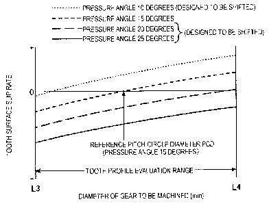
the tooth profile evaluation range of the tooth surface 5. As a result, within
the
tooth profile evaluation range of the tooth surface 5 of the machined gear 4,
the
position does not exist at which relative movement in the tooth profile
direction
A of the workpiece 4 does not occur between the surface of the threaded
grinding wheel 32 and the workpiece 4 to be machined. Thus, the tooth surface
slip rate, at which the threaded grinding wheel 32 moves with respect to the
workpiece 4 in the tooth profile direction A of the workpiece 4, does not
become zero, and it is possible to improve the surface uniformity in the tooth
profile evaluation range of the tooth surface 5 of the gear 4.
[0041]
Next, with reference to FIG. 11, a gear machining apparatus according to
a second embodiment of the present invention will be described. The gear
machining apparatus of the present embodiment is different from the gear
machining apparatus according to the first embodiment described above in that
the dresser is designed to be shifted so that the pressure angle thereof is
increased, and a position, at which relative movement in the tooth profile
direction of the gear 40 does not occur between the surface of the threaded
grinding wheel 32 and a gear 40 to be machined, is moved so as to be larger
than the tooth profile evaluation range.
Here, only aspects of the second embodiment of the present invention
that are different from those of the first embodiment will be described. The
same reference signs are assigned to similar portions in the drawings, and
descriptions thereof will be omitted.
[0042]
A description will be made of the fact that, in the second embodiment of
the present invention, by forming the dresser designed to obtain an intended
gear 40 as a dresser 42 that is designed to be shifted so that the pressure
angle
of the dresser is increased, it is possible to cause the value of the tooth
surface
slip rate to be smaller than zero in the tooth profile evaluation range of the
gear
40.
FIG. 11 is a line chart comparatively showing tooth surface slip rates, in
the tooth profile evaluation range, of respective tooth surfaces of a gear
shaped
CA 02898426 2015-07-16
22
by the second embodiment of the present invention and the gear shaped by the
conventional apparatus.
In FIG. 11, the horizontal axis indicates a diameter [mm] of the gear to
be machined in the gear 4, and the vertical axis indicates the value of the
tooth
surface slip rate using plus and minus values, with the reference value at 0.
The tooth profile evaluation range is a range between a tooth profile
evaluation
range lower limit diameter L3 of the tooth surface and an outer diameter L4 in
the diameter of the gear to be machined.
As illustrated in FIG. 11, in the conventional apparatus, when the dresser,
which is designed to obtain the originally intended gear 40, has the pressure
angle of the dresser set at 15 degrees, the value of the rate of tooth surface
slip,
which is performed by a threaded grinding wheel shaped by the dresser with
respect to the workpiece, becomes zero at the position of the reference pitch
circle diameter PCD, at the time of grinding, within the tooth profile
evaluation
range of the diameter of the gear to be machined.
[0043]
When the dresser is changed so as to form the dresser 42 in which the
pressure angle of 15 degrees is increased to the pressure angle a of 25
degrees
by the shift design, the value of the rate of tooth surface slip, which is
performed by a threaded grinding wheel 44 shaped by the shift-designed
dresser 42 with respect to the workpiece 40, becomes smaller than zero at the
outer diameter L4 of the tooth profile evaluation range of a tooth surface 45.
More specifically, when the shift-designed dresser 42 is used to shape the
threaded grinding wheel 44 and the threaded grinding wheel 44 grinds the
workpiece 40, the position, at which relative movement in the tooth profile
direction of the gear 40 does not occur between the surface of the threaded
grinding wheel 32 and the gear 40 to be machined, is moved so as to be
arranged at a position of a diameter which is even larger than the outer
diameter L4, namely, the upper limit of the tooth profile evaluation range of
the
tooth surface 45, and the value of the tooth surface slip rate becomes greater
than zero within the tooth profile evaluation range (the value of the tooth
surface slip rate becomes a minus value). Thus, the threaded grinding wheel 44
can grind the workpiece 40 while moving in the tooth profile direction of the
workpiece 40, and it is possible to improve the surface uniformity in the
tooth
profile evaluation range of the tooth surface 45 of the gear 4.
[0044]
With respect to the dresser 42, even when an originally designed dresser
has a different pressure angle, by changing the pressure angle of the
originally
CA 02898426 2015-07-16
23
designed dresser to the increased pressure angle a by the shift design with
respect to the dresser 42 in the same manner, it is possible to move the
position,
at which the above-described relative movement in the tooth profile direction
of the gear 40 does not occur, to be arranged at the position of the diameter
which is larger than the outer diameter L4 of the tooth profile evaluation
range
and to cause the value of the tooth surface slip rate to become greater than
zero
in the tooth profile evaluation range. Thus, the threaded grinding wheel 44
can
perform grinding with respect to the workpiece 40 while moving in the tooth
profile direction of the workpiece 40, and it is possible to improve the
surface
uniformity in the tooth profile evaluation range of the gear 4.
[0045]
With the gear machining apparatus according to the second embodiment
of the present invention, the dresser 42 is designed to be shifted so that the
pressure angle a thereof is increased, and the position, at which relative
movement in the tooth profile direction of the gear 40 does not occur between
the surface of the threaded grinding wheel 32 and the gear 40 to be machined,
is moved to an outer side of the tooth profile evaluation range of the tooth
surface 45. Thus, the above-described position, at which relative movement
does not occur, does not exist within the tooth profile evaluation range of
the
tooth surface 45 of the gear 40. As a result, the tooth surface slip rate, at
which
the threaded grinding wheel 44 moves with respect to the workpiece 40 in the
tooth profile direction A of the workpiece 40, does not become zero, and thus,
it is possible to improve the surface uniformity in the tooth profile
evaluation
range of the tooth surface 45 of the gear 40.
Reference Signs List
[0046]
1 Gear machining apparatus
4 Workpiece (gear)
32 Threaded grinding wheel
36 Dresser
Gear to be machined
42 Dresser
44 Threaded grinding wheel
35 A Tooth profile direction
B Tooth trace direction
Li Tooth profile evaluation range lower limit diameter
L2 Outer diameter portion
CA 02898426 2015-07-16
24
L3 Tooth profile evaluation range lower limit diameter
L4 Outer diameter
PCD Reference pitch circle diameter