Note: Descriptions are shown in the official language in which they were submitted.
CA 02898548 2015-07-28
"REVOLVING BALL SEAT FOR HYDRAULICALLY
ACTUATING TOOLS"
FIELD
Embodiments disclosed herein general relate to ball-actuated
downhole tools, and more particularly, related to ball-actuated tools having a
revolving ball seat.
BACKGROUND
In the completion of oil and gas wells, downhole tools are mounted on
a workstring, such as a drill string, a landing string, a completion string,
or a
production string. The workstring can be any type of wellbore tubular, such as
casing, liner, tubing, and the like. A common operation performed downhole
temporarily obstructs the flow path within the wellbore to allow the internal
pressure
within a section of the workstring to be increased. In turn, the increased
pressure
operates hydraulically actuated tools. For example, a liner hanger can be
hydraulically operated to hang a liner in the well's casing.
Sealably landing a ball on a ball seat provides a common way to
temporarily block the flow path through the wellbore tubular so a hydraulic
tool
above the seat can be operated by an increase in pressure. Historically,
segmented
dogs or keys have been used create the ball seat for landing the ball.
Segmented
ball seats may be prone to fluid leakage and tend to require high pump rates
to
shear open the ball seat. Additionally, the segmented ball seat does not
typically
open to the full inner diameter of the downhole tubular so the ball seat may
eventually need to be milled out with a milling operation.
Alternatively, a hydro-trip mechanism can use collet fingers that
deflect and create a ball seat for engaging the dropped ball. In this type of
ball seat,
the collet-style mechanism opens up in a radial direction when shifted past a
larger
diameter groove. However, the collet-style ball seat is more prone to leaking
than
solid ball seats, and the open collet fingers exposed inside the tubular
create the
1
CA 02898548 2015-07-28
potential for damaging equipment used in subsequent wellbore operations.
Any of the hydraulic tools that are to be actuated and are located
above the ball seat need to operate at a pressure below whatever pressure is
needed to eventually open or release the ball seat. Internal pressures can
become
quite high when breaking circulation or circulating a liner through a tight
section. To
avoid premature operation of the tool at these times, the pressure required to
open
or to release a ball seat needs to be high enough to allow for a sufficiently
high
activation pressure for the tool. For example, ball seats can be assembled to
open
or release at a predetermined pressure that can exceed 3000 psi.
Once the hydraulically-actuated tool, such as a liner hanger or packer
is actuated, operators want to remove the obstruction in the tubular's flow
path.
Since the ball seat is a restriction in the wellbore, it must be opened up,
moved out
of the way, or located low enough in the well to not interfere with subsequent
operations. For example, operators will want to move the ball and seat out of
the
way. Various ways can be used to reopen the tubular to fluid flow.
Commonly, the ball seat is moved out of the way by having it drop
downhole. For example, with the ball landed on the seat, the increasing
pressure
above the ball seat can eventually cause a shearable member holding the ball
seat
to shear, releasing the ball seat to move downhole with the ball. However,
this
leaves the ball and ball seat in the wellbore, potentially causing problems
for
subsequent operations. Additionally, this may require the removal of both the
ball
and ball seat at a later time.
In another way to reopen fluid flow through the tubular, increased
pressure above the ball seat can eventually force the ball to deformably open
the
seat, which then allows the ball to pass through. In these designs, the outer
diameter of the ball represents a maximum size of the opening that can be
created
through the ball seat. This potentially limits the size of subsequent
equipment that
can pass freely through the ball seat and further downhole without the risk of
damage or obstruction.
Ball seats may also be milled out of the tubular to reopen the flow
2
CA 02898548 2015-07-28
path. For example, ball seats made of soft metals, such as aluminum or cast
iron,
are easier to mill out; however, they may not properly seat the ball due to
erosion
caused by high volumes of drilling mud being pumped through the reduced
diameter of the ball seat. Also, if additional landings are to be made,
interference
from the first ball seat being released downhole may also prevent the ball
from
sealably landing on another ball seat below.
The subject matter of the present disclosure is directed to overcoming,
or at least reducing the effects of, one or more of the problems set forth
above.
SUMMARY
A downhole apparatus or tool for use with a deployed plug and applied
fluid pressure has a housing, a piston, and a seat. The housing defines a
bore, and
the piston is disposed in the bore of the housing and is biased to move from a
first
position to a second position. The piston in the first position is near the
seat, while
the piston in the second position is away from the seat.
The seat is disposed in the bore of the housing and is operably
connected to the piston. In particular, in response to movement of the piston
from
the first position near the seat to the second position away from the seat,
the seat is
rotatable from a first orientation for engaging the deployed plug to a second
,
orientation for passing the deployed plug. The seat in the first orientation
with the
deployed plug engaged therein can capture at least some of the applied fluid
pressure, which can then be used for various operations purposes.
In one example of the tool, the piston can have an operable
connection to the seat, and the operable connection can transfer axial
movement of
the piston away from the seat to rotational movement of the seat. The axial
movement of the piston can result from mechanical bias from a biasing member
or
spring instead of hydraulic fluid pressure.
The operable connection can include a linkage operably coupled
between the piston and the seat, where the linkage on the piston moved from
the
first position toward the seat to the second position away from the seat
rotates the
3
CA 02898548 2015-07-28
seat from the first orientation to the second orientation.
In use, when the seat engages the deployed plug, the seat and plug
hold the applied fluid pressure in the bore of the housing. This applied fluid
pressure
can then be used to actuate the tool or to actuate another tool disposed on a
toolstring uphole of the tool.
A connection at least temporarily holds the seat axially in the bore of
the housing. The connection eventually releases the seat in response to the
applied fluid pressure communicated in the bore against the deployed plug
engaged
in the seat in the first orientation. After the seat has moved axially in the
bore once
released, the seat has a lock holding the seat axially in the bore of the
housing.
After the piston and seat have moved in the housing and the applied
fluid pressure has achieved its purposes (i.e., actuating the tool or another
tool), the
piston moves from the first position near the seat to the second position away
from
the seat in response to a reduction of the applied fluid pressure. For
example, at
least one biasing member, such as a spring disposed in the bore, can bias the
piston toward the second position away from the seat. The movement of the
piston
away from the seat rotates the seat from the first orientation via the
operable
connection to the second orientation so the deployed plug can pass.
In one configuration, the tool is positionable on a toolstring. A second
tool is positionable on the toolstring uphole of the first tool and is
actuatable with the
applied fluid pressure captured in the toolstring against the deployed plug
engaged
in the seat.
In another configuration, the tool can be a hydraulically-actuated tool,
a sliding sleeve, a packer, and a liner hanger. For example, the tool can have
a tool
body with a main bore in which the housing is movably disposed. The tool body
can
define a port communicating outside the main bore, and the housing can be
movable in the tool body relative to the port. A connection can at least
temporarily
hold the housing in the main uore of the tool body so that applied fluid
pressure
against the deployed plug in the seat may be required to shift the housing
open
relative to the port. For a sliding sleeve, this port in the tool body can be
an external
4
CA 02898548 2015-07-28
port for communicating fluid outside the tool. For a packer, liner hanger, or
the like,
the port can communicate with a piston or other hydraulic mechanism.
In a method of operating a downhole tool with a deployed plug and
applied fluid pressure, the deployed plug engages in a seat rotated in a first
orientation in a bore of the tool. Engaging the deployed plug in the seat
rotated in
the first orientation can involve actuating the tool or another tool in
response to the
applied fluid pressure against the deployed plug engaged in the seat. To
actuate
the tool, for example, a sleeve can be shifted relative to an external flow
port in the
tool. To actuate the other tool, for example, at least one of a hydraulically-
actuated
tool, a sliding sleeve, a packer, and a liner hanger can be actuated with the
applied
fluid pressure.
Eventually, the seat engaging the deployed plug and a piston coupled
to the seat can move in response to the applied fluid pressure. For example,
moving the seat and the piston can involve releasing a temporary hold of the
seat
and the piston in response to the applied fluid pressure.
The piston then moves away from the seat in response to a
subsequent reduction of the applied fluid pressure. To move the piston away
from
the seat, the seat can lock axially in the tool, and the piston can be biased
in a
direction away from the seat. In response to the movement of the piston away
from
the seat, the seat rotates from the first orientation to a second orientation,
and the .
engaged plug is released from the seat bore in response to the rotation of the
seat
to the second orientation.
In one embodiment, the seat can have a first section of a catch
member aligned with the piston and having the seat rotatably supported
thereon.
The seat can also have a second section of the catch aligned with the piston
and
having the seat rotatably supported thereon. The first and second sections can
be
cylindrical bodies or sleeves.
The first section can have at least one segment rotatably connected to
a rotation point on the seat. The second section can include a connection at
least
temporarily holding the seat axially in the bore of the housing. The
connection can
5
CA 02898548 2015-07-28
release the seat to move axially in response to fluid pressure communicated in
the
bore against the deployed plug engaged in the seat while in the first
orientation.
The second section can also include a lock holding the seat axially in the
bore of the
housing after the seat has moved axially in the bore once released.
In another embodiment, the piston can have a first sleeve disposed in
the bore of the housing and defining a first axial bore therethrough. The seat
can
have a second sleeve of a catch member and a rotatable body. The second sleeve
can define a second axial bore therethrough in line with the first axial bore
of the
piston. The body of the seat can be rotatably supported on the second sleeve.
The body can have a first passage with an opening for entry of the
deployed ball from the second axial bore and with an opposite seat profile for
engaging the deployed ball. The body can also have a second passage offset
from
the first passage and aligning with the second axial bore when the seat has
the
second orientation. The second passage can define an equivalent inner
dimension
to the second axial bore, and the second axial bore can define an equivalent
inner
dimension to the first axial bore.
The foregoing summary is not intended to summarize each potential
embodiment or every aspect of the present disclosure.
BRIEF DESCRIPTION OF THE DRAWINGS
Figure 1 illustrates a wellbore assembly having a revolving ball seat
for actuating a hydraulically actuated tool;
Figure 2A illustrates a cross-sectional view of a downhole tool having
a revolving ball seat according to the present disclosure in a run-in
condition;
Figure 2B illustrates a cross-sectional view of the downhole tool
having the revolving ball seat in an intermediate condition with the ball seat
sheared
free;
Figure 2C illustrates a cross-sectional view of the downhole tool
having the ball released from the revolving ball seat in an actuated
condition;
Figures 3A-3B illuStrate internal components of the revolving ball seat
6
CA 02898548 2015-07-28
in the run-in condition and the actuated condition, respectively, having one
type of
operable connection;
Figures 4A-4B illustrate internal components of the revolving ball seat
in the run-in condition and the actuated condition, respectively, having
another
operable connection;
Figures 5A-5B illustrate internal components of the revolving ball seat
in the run-in condition and the actuated condition, respectively, having yet
another
operable connection;
Figures 6A-6B illustrate cross-sectional views of a sliding sleeve in
closed and opened conditions having a revolving ball seat assembly according
to
the present disclosure;
Figures 7A-7B illustrate cross-sectional views of another sliding sleeve
in closed and opened conditions having a revolving ball seat assembly
according to
the present disclosure; and
Figures 8A-8C illustrate cross-sectional views of another downhole
tool having a revolving ball seat according to the present disclosure in run-
in,
intermediate, and actuated conditions.
DETAILED DESCRIPTION OF THE DISCLOSURE
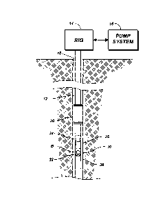
Fig. 1 illustrates a wellbore tubular 12 disposed in a wellbore 10. A
hydraulically-actuated tool 20, such as a packer, a liner hanger, or the like,
is
disposed along the wellbore tubular 12 uphole from a downhole tool 30. The
disclosed downhole tool 30 can be used to set the hydraulically-actuated tool
20
and has a rotating revolving ball seat 32 that allows a setting ball, plug, or
other
deployed device B to selectively land and then pass therethrough.
When operators wish to actuate the hydraulically-actuated tool 20, for
instance, an appropriately sized ball B is dropped from the rig 14 to engage
in the
revolving ball seat 32 of the downhole tool 30. With the ball B engaged in the
seat
32, operators use the pumping system 16 to increase the fluid pressure in the
wellbore tubular 12 uphole from the tool 30. In turn, the increased tubing
pressure
7
CA 02898548 2015-07-28
actuates an appropriate mechanism in the hydraulically-actuated tool 20 uphole
of
the revolving ball seat 32. For example, the tool 20 may be a hydraulically-
set
packer that has a piston that compresses a packing element in response to the
increased tubing pressure.
Once the tool 20 is actuated, operators will want to reopen fluid
communication downhole by moving the seated ball B out of the way. Rather than
milling out the ball B and seat 32 or shearing the ball B and seat 32 out of
the way
with increased pressure, the revolving ball seat 32 of the present disclosure
allows
operators to open the revolving seat 32 and pass the ball B by rotating the
seat 32.
Rather than using translated motion, the revolving ball seat 32 uses
rotation to let the ball B pass the seat 32. For example, the ball B lands on
the seat
32, and pressure is increased so the ball seat 32 moves downward linearly.
This
movement compresses a biasing member 35 while simultaneously shifting a piston
34 downward. The seat 32 moves downward and locks in place with a lock 36.
With the seat 32 locked in place, fluid can bypass the seat 32 to equalize the
pressure above and below the seat 32, although pressure equalization is not
strictly
required to release the ball B.
To release the ball B, tubing pressure is diminished. The piston 34
moves away from the seat 32 by the biasing member 35, and the ball seat 32
rotates to pass the ball B. As the ball B is released, the seat 32 does not
lift up the
hydrostatic fluid above the seat 32. Turning now to more details of a downhole
tool
having a revolving ball seat, Fig. 2A illustrates a cross-sectional view of a
downhole
tool 50 having a revolving ball seat 80 in a run-in condition. Fig. 2B
illustrates a
cross-sectional view of the downhole tool 50 having the revolving ball seat 80
in an
intermediate condition with the ball seat 80 sheared free, and Fig. 2C
illustrates a
cross-sectional view of the downhole tool 50 having the ball released from the
revolving ball seat 80 in an actuated condition.
The tool 50 includes an outer housing 52, which couples to sections of
wellbore tubular (not shown) in a conventional manner, by threads, couplings,
or the
like. The housing 52 itself may comprises several tubular components to
facilitate
8
CA 02898548 2015-07-28
assembly. Inside a bore 54 of the housing 52, the tool 50 has a piston 60 and
a
catch 70 temporarily fixed in the housing 52 in the run-in condition with one
or more
temporary connections 94, such as shear pins.
The piston 60 is a sleeve disposed in the bore 54 of the housing 52
and defines a first axial bore 62 therethrough. The axial bore 62 allows for
passage
of the deployed ball B to the catch 70, but the bore 62 also acts as the main
tubular
bore for the tool 50 and is suitably sized as such.
The piston 60 is biased to move from a first position (Figs. 2A-2B) to a
second position (Fig. 2C). These positions are relative to the catch 70 and
not
necessarily relative to the housing 52, as will be apparent below. At least
one
biasing member, such as spring 66, disposed in the bore 54 can bias the piston
60
toward the second position (e.g., away from the catch 70). For example, a head
on
the piston 60 can engage against an end of the spring 66¨the other end of
which
engages inside the housing 52 (e.g., against an internal shoulder in the inner
bore
54).
The catch 70 disposed in the bore 54 of the housing 52 defines a
second axial bore 72 therethrough in line with the first axial bore 62 of the
piston 60.
This second bore 72 also acts as the main tubular bore for the tool 50 and is
appropriately sized.
The catch 70 has the revolving ball seat 80 disposed thereon. The
seat 80 is operably connected to the piston 60 and is rotatable from a first
orientation (Figs. 2A-2B) to a second orientation (Fig. 20). As will be
described
below, rotation of the seat 80 is in response to movement of the piston 60
from the
first position (e.g., near the catch 70 as in Fig. 2B) to the second position
(e.g.,
distanced from the catch 70 as in Fig. 2C). The seat 80 in the first
orientation (Figs.
2A-2B) can engage the deployed plug or ball B, while the seat 80 in the second
orientation (Fig. 2C) can pass the deployed ball B further on through the tool
50.
As shown in Fig. 2A, the piston 60 in the first position is disposed
toward the catch 70. This is also true for Fig. 2B when the piston 60 and
catch 70
are moved axially in the housing 52 by the communicated fluid pressure against
the
9
CA 02898548 2015-07-28
seated plug breaking the temporary connections 94. As shown in Fig. 2C, the
piston 60 in the second position is disposed away from the catch 70, and an
operable connection 65 on the piston 60 rotates the seat 80 from the first
orientation
(Fig. 2B) to the second orientation (Fig. 2C).
As shown more particularly, the catch 70 includes an upper mandrel
or section 90a and a lower mandrel or section 90b with the revolving seat 80
disposed therebetween. Fitting in a space between the distal ends of the two
mandrels 90a-b, sealing members (not shown), such as sealing rings or the
like,
can be used between the sections' ends and the outer surface of the seat 80 to
maintain fluid isolation therebetween, if necessary.
The first mandrel 90a is aligned with the piston 60 and has the seat 80
rotatably connected thereto. For example, Fig. 3A illustrates internal
components of
the revolving ball seat 80 and related components in the run-in condition, and
Fig.
3B illustrates the internal components in the actuated condition. As shown,
segments or legs 95 of the first mandrel 90a extend on the sides of the seat
80 and
rotatably connect to rotation points or axels 85 on the sides of the seat 80
about
which the seat 80 can rotate.
As again shown in Fig. 2A, the second mandrel 90b is also aligned
with the piston 60 and has the seat 80 rotatably supported thereon. The second
mandrel 90b may or may not be connected to the first mandrel 90a and may or
may
not have legs as with the first mandrel 90a. Overall, the seat 80 may rest
supported
against the top of the second mandrel 90b. Other configurations can be used as
will be appreciated.
Internal features of the seat 80 are shown in Figs. 2A-2C, and some of
the external features of the seat 80 are shown Figs. 3A-3B. The seat 80 is a
spherical body and defines passages 81 and 83 therethrough. On either side of
the
spherical body, the seat 80 has the axels 85 or points of rotation about which
the
seat 80 is arranged to rotate.
The piston 60 having the operable connection 65 operably couples to
the seat 80. As shown in Figs. 3A-3B, for example, the operable connection 65
can
CA 02898548 2015-07-28
be a linkage that connects with one hinged connection 64 to the piston 60 and
connects with another hinged connection 67 to the seat 80. This second hinged
connection 67 is eccentric to the axels 85 of rotation of the seat 80
connected to the
first mandrel 90a.
As can be surmised from the arrangement, movement of the piston 60
in one direction away from the catch 70 rotates the seat 80 around its axis,
while
movement of the pistons 60 and catch 70 in unison with one another does not
cause the seat 80 to rotate. Therefore, as shown in Fig. 3B, the piston 60
moved
away from the upper mandrel 90a pulls the linkage 65. As the piston 60 travels
away from the seat 80, the linkage 65 then rotates the seat 80 about 90-
degrees.
Although one side is shown, the opposite side could have a comparable
arrangement of linkage 65, hinged connection 67, leg 95, etc.
As indicated above, axial movement of the first connection 64 on the
piston 60 moved away from the catch 70 and the seat 80 is transferred into
rotational motion for rotating the seat 80 on the catch 70. Mechanisms other
than a
linkage can be used to transfer the axial movement of the piston 60 away from
the
catch 70 into rotational motion for rotating the seat 80 on the catch 70. For
example, other than a linkage, the operable connection 65 between the piston
60
and the seat 80 can use rack and pinion gears, lever, cam, and the like. Some
of
these are disclosed below.
As for the passages of the seat 80, a first passage 81 has an opening
for entry of the deployed ball B from the catch's axial bore 72 and has an
opposite
seat profile 82 for engaging the deployed ball B. When the seat 80 is in the
first
orientation (Fig. 2A), the ball B can pass through the catch's bore 72, enter
through
the opening of the first passage 81, and land in the seat profile 82. When
pressure
is communicated against the seated ball B, the ball B can remain engaged in
the
seat profile 82.
A second passage 83 of the seat 80 is offset (e.g., orthogonal) to the
first passage 81. As shown in Fig. 20, this second passage 83 aligns with the
catch's axial bore 72 when the seat 80 has the second (rotated) orientation.
11
CA 02898548 2015-07-28
Preferably, the second passage 83 defines an equivalent inner dimension to the
catch's axial bore 72. Similarly, the catch's axial bore 72 preferably defines
an
equivalent inner dimension to the piston's axial bore 62. In this way, the
tool 50 can
have a consistent main bore for passage of other tools, tubulars, coiled
tubing,
wireline, etc.
Operation of the tool 50 is shown in Figs. 2A-2C. As noted above, the
tool 50 is shown set in a run-in position in Fig. 2A. A ball B has been
dropped to
land on the ball seat profile 82 inside the ball seat's passage 81. The seat
80
engaging the deployed ball B holds fluid pressure in the housing 52. With the
ball B
seated, operators can pressure up the wellbore tubing uphole of the seat 80 to
the
required pressure to actuate any hydraulically actuated tools (20: Fig. 1).
Once such tools (20) are actuated or even before, pressure can be
used to actuate the downhole tool 50. The pressure uphole of the seated ball B
acts against the seated ball B and eventually shears the temporary connections
94.
Conventional shear pins or other temporary connections can be used to
initially hold
the catch 70 (and concurrently the piston 60) in their run-in position (Fig.
2A) and
can subsequently break once the required pressure level is reached (Fig. 2B).
Several options are available for holding the catch 70.
As shown in Fig. 2A, the second mandrel 90b has the connections 94
at least temporarily holding the catch 70 axially in the bore 54 of the
housing 52.
The connections 94 release the catch 70 to move axially in response to fluid
pressure communicated in the bore 54 against the deployed ball B engaged in
the
seat 80 in the first orientation. Although the one or more shear pins 94 or
other
temporary connections can affix the lower mandrel 90b of the catch 70 in the
housing 52, shear pins and the like can be used elsewhere on the assembly.
With the catch 70 and piston 60 free to move in the housing 54, the
applied pressure against the ball B in the seat 80 moves the piston 60 and
catch 70
together in the housing's bore 54 until the catch 70 shoulders out in the bore
54, as
shown in Fig. 2B.
As then shown in Fig. 2B, the second mandrel 90b has a stop or lock
12
CA 02898548 2015-07-28
96 that holds the catch 70 axially in the bore of the housing 52 after the
catch 70
has moved axially in the bore 54 once released. This lock 96 can be an
expandable
lock ring or C-ring disposed on the second mandrel 90b that expands into a
surrounding profile or groove on the housing's bore 54 when the second mandrel
90b moves axially to its downward position. Other forms of locking can be
used.
With the second mandrel 90b locked in place, fluid can bypass the
seat 80 to equalize the pressure above and below the seat 80. The equalization
is
possible due to the movement of the 0-ring seal 97 reaching the increased
dimension inside the housing's bore 54 when the lock ring 96 engages an
internal
shoulder of the bore 54. Fluid uphole of the seat 80 can pass through the
annular
space between the second mandrel 90b and the housing's bore 54 to downhole the
seat 80.
The above pressure equalization is not strictly required for operation
of the tool 50. Instead, the 0-ring seal 97 may remain engaged and sealed in
the
housing's bore 54 by either being positioned elsewhere on the mandrel 90b
(i.e.,
uphole of the lock ring 96) or by keeping the 0-ring seal 97 in its shown
position and
maintaining the bore 54's dimension with a discrete groove for the lock ring
96).
Once operations are complete, pressure buildup in the tool 50 is
diminished either through the pressure equalization described above, by
purposeful
decrease of the pressure at the surface, and/or by some other release. The
spring
66 forces the piston 60 away from the catch 70, which remains held in place as
shown in Fig. 2C. The piston 60 moves from the first position near the catch
70 to
the second position away from the catch 70 in response to a reduction of the
communicated fluid pressure. The linear movement of the piston 60 is
transmitted
to the revolving ball seat 80 through the linkage 65 so that the movement of
the
piston 60 away from the catch 70 rotates the seat 80 from the first
orientation to the
second orientation.
Because pressure has pushed the ball B against the seat profile 82
and the ball B is sized to fit inside the seat's outer diameter, the ball B
may rotate
with the seat 80 without wedging against the mandrel 52, catch 70, or other
13
CA 02898548 2015-07-28
component. If the ball B is loose in the seat 82 to an extent, then the size
of the ball
B, the seat profile 82, offset bore 83, etc. may be configured to prevent
trapping or
wedging of the ball B. Either way, with the ball seat 80 rotated, the ball B
is
exposed to the throughbore of the tool 50, and the ball B is free to pass
through the
tool 50. At this point, other operations can be performed through the tool 50
without
the constriction of the seat 50.
Previous embodiments have discussed using a pivotable linkage as
the operable connection 65 between the piston 60 and the revolving ball seat
80.
As discussed herein, alternative forms of operable connections can be used.
For
example, Figs. 4A-4B illustrate internal components having another arrangement
in
the run-in condition and the actuated condition, respectively. Here, the
operable
connection 65a is an arm that connects with a fixed point 64a on the piston 60
and
couples with a rack and pinion arrangement 67a to the seat 80.
As can be surmised from the arrangement, movement of the piston 60
in one direction away from the catch 70 rotates the seat 80 in one direction
around
its axis 85, while movement of the pistons 60 and catch 70 in unison with one
another would not cause the seat 80 to rotate. Therefore, as shown in Fig. 4B,
the
piston 60 moved away from the upper mandrel 90a pulls the arm 65a. As the
piston
60 travels away from the seat 80, the rack and pinion arrangement 67a then
rotates
the ball seat 80 about 90-degrees. Although one side is shown, the opposite
side
could have a comparable arrangement.
In another example, Figs. 5A-5B illustrate internal components having
another arrangement in the run-in condition and the actuated condition,
respectively. The operable connection 65b is an arm that connects with a fixed
point 64b on the piston 60 and couples with a pin and slot arrangement 67b to
the
seat 80. As can be surmised from the arrangement, movement of the piston 60 in
one direction away from the catch 70 rotates the seat 80 around its axis 85,
while
movement of the pistons 60 and catch 70 in unison with one another would not
cause the seat 80 to rotate. Therefore, as shown in Fig. 4B, the piston 60
moved
away from the upper mandrel 90a pulls the arm 65b. As the piston 60 travels
away
14
CA 02898548 2015-07-28
from the seat 80, the pin and slot arrangement 67b then rotates the ball seat
80
about 90-degrees. Although one side is shown, the opposite side could have a
comparable arrangement.
Previous embodiments have discussed using the revolving ball seat
80 in a downhole tool 50 that is separate from any hydraulically-actuated tool
(20:
Fig. 1) disposed on a wellbore tubular (12). In other embodiments, the
revolving
ball seat 80 can actually be incorporated into a hydraulically-actuated tool,
such as
a packer, a liner hanger, or the like. In fact, the revolving ball seat 80 can
actually
be used directly as a part of the hydraulic actuating mechanism of such a
tool.
As one particular example, a sliding sleeve can incorporate the
revolving ball seat as part of its mechanism for hydraulically opening the
sliding
sleeve for fracture treatments or other operations. Figs. 6A-6B show a sliding
sleeve 100 in closed and opened states. The sliding sleeve 100 has a tool body
110 defining one or more ports 114 communicating the body's main bore 112
outside the sleeve 100. An inner sleeve 120 disposed in the tool's bore 112
covers
the ports 114 when the inner sleeve 120 is in a closed condition, as shown in
Fig.
6A.
A dropped ball B engages in a revolving ball seat assembly 150 that is
incorporated into the inner sleeve 120. Thus, as shown, the revolving ball
seat
assembly 150 is similar to that disclosed above and has a housing 152, a
piston
160, a catch 170, and a seat 180, which are all incorporated into or part of
the inner
sleeve 120 movably disposed in the main bore 112 of the sleeve's body 110. In
general, the assembly's housing 52 can be connected to or part of the inner
sleeve
120.
Pressure applied against the seated ball B eventually shears a set of
first shear pins 125 or other temporary connections that hold the inner sleeve
120 in
the housing's bore 112. Now free to move, the inner sleeve 120 moves with the
applied pressure in the bore 112 and exposes the housings ports 114, as shown
in
Fig. 4B. Fluid treatment can then be performed to the annulus surrounding the
sliding sleeve 100.
CA 02898548 2015-07-28
When it is then desired to open the revolving ball seat assembly 150,
additional pressure applied against the seated ball B, such as during a
fracture
treatment, can act against the seated ball B. Eventually, when a predetermined
pressure level is reached, one or more shear pins 194 or other breakable
connections can break so that the applied pressure moves the piston 160 and
catch
170 of the assembly 150 in unison downward in the sleeve 120. Then, when
pressure is diminished, the piston 160 of the assembly 150 can move away from
the
catch 170 and rotate the ball seat 180 to release the ball B.
In the above discussion, the shear pins 125 holding the sleeve 120
have a lower pressure setting than the shear pins 194 holding the catch 170.
This
allows the sleeve 120 to open with pressure applied against the seat 180 while
the
seat's catch 170 remains in its initial state. Eventual pressure can then
.break the
shear pins 194 for the catch 170.
A reverse arrangement of the activation can also be used. For
example, a ball B can be dropped to the seat 180 and applied pressure can
shear
the shear pins 194 so the piston 160 and catch 170 are free to move in unison.
Then, when pressure builds to a sufficient level, the shear pins 125 of the
sleeve
120 can eventually break, allowing the sleeve 120 to shift open.
Although the external ports 114 for the sliding sleeve 100 are
disposed uphole of the revolving ball seat assembly 150 in Figs. 6A-6B, an
opposite
arrangement can be provided, as shown in Figs. 7A-7B. Here, the inner sleeve
120 has slots 124 that align with the housing ports 114 disposed downhole from
the
seat 180 when the inner sleeve 120 is moved downhole in the tool's housing
110.
The other components of this configuration can be essentially the same as
those
described previously.
In the arrangement of Figs. 2A-2C, the shear pins 94 or other
temporary connections are used between the catch's lower mandrel 90b and the
housing 52. Other arrangements can be used. In one additional option, the
catch
70 and the piston 60 may be interconnected to one another by shear pins or
other
temporary connections so that they are forced to move together.
16
CA 02898548 2016-11-09
As shown in Figs. 8A-8C, cross-sectional views of another downhole
tool 50 having a revolving ball seat according to the present disclosure is
shown in
run-in, intermediate, and actuated conditions. Many features of this tool 50
are the
same as discussed above so that like reference numerals are used. As shown
here, rather than having a temporary connection or shear pins temporary
holding
the catch 70 (esp. the lower mandrel 90b) in the bore 54 of the housing 52, a
temporary connection 94a instead temporarily holds the piston 60 and the catch
70
together to move jointly together.
As shown in Fig. 8A, a ball B engages in the seat 80 as before. Fluid
pressure applied against the ball B engaged in the seat 80 jointly moves the
piston
60 and catch 70. In this joined movement and as shown in Fig. 8B, the piston
60
may then shoulder out in the housing 52 before the catch 70 shoulders out.
Therefore, with the ball B seated in the seat 80, communicated pressure can
shift
the piston 60 and catch 70 together against the bias of the spring 66.
Eventually,
the piston 60 shoulders out inside the housing 52, while the catch 70 does
not.
When the communicated pressure acting against the seat 80 reaches a shear
level
of the temporary connection 94a, the catch 70 can shear free as it is moved
away
from the piston 60.
The catch 70 can then lock in a downward position with the lock ring
96. In one option, the ball seat 80 can rotate as the catch 70 is allowed to
continually move away from the shouldered piston 70. Alternatively or in
addition to
this, another option can use the bias of a spring 66 as before to move the
piston 60
away from the held catch 70 to rotate the seat 80 and release the ball B. This
and
other arrangements can be suitable for certain implementations.
The foregoing description of preferred and other embodiments is not
intended to limit or restrict the scope or applicability of the inventive
concepts
conceived of by the Applicants. Although reference to use of a ball B has been
used throughout the disclosure, it will be appreciated that a setting ball, a
deployed
device, or other type of "plug" can be used. Although the tool 100 of Figs. 6A-
6B
and 7A-7B has been disclosed as a sliding sleeve having an inner sleeve 120
17
CA 02898548 2015-07-28
movable relative to ports 114, it will be appreciated that the tool 100 could
be any
other type of tool, such as a hydraulically actuated tool, a packer, a liner
hanger,
etc. with the sleeve 120 constituting a piston or other hydraulic mechanism
actuating a component, such aP a slip, a packer, etc. Alternatively, the
sleeve 120
can move to expose an internal port of the tool, through which fluid pressure
can
communicate with a hydraulic mechanism.
It will also be appreciated with the benefit of the present disclosure
that features described above in accordance with any embodiment or aspect of
the
disclosed subject matter can be utilized, either alone or in combination, with
any
other described feature, in any other embodiment or aspect of the disclosed
subject
matter.
18