Note: Descriptions are shown in the official language in which they were submitted.
CA 02898649 2015-07-20
WO 2014/125127 PCT/EP2014/053159
- 1 -
"A scour remediation and mitigation apparatus"
Introduction
The present disclosure relates to a scour remediation and scour mitigation
method
and apparatus.
In particular, the present disclosure is directed towards a simple and
effective
apparatus for remediating scour damage and preventing, or at least mitigating
against future scour from occurring adjacent underwater structures and
particularly at
the base of posts, masts, piles, jetties, moorings, piers and other such
structures
which have been affixed to the seabed, or, structures which are located close
to the
seabed such that scouring can occur due to the position of the structure. It
will be
also understood that the remediation and mitigation of scouring around other
objects
and structures adjacent a seabed is envisaged. For example, scouring is also
known
to occur in the environs of seabed cables and piping and it is envisaged that
the
present disclosure would have applicability in the remediation and mitigation
of
scouring adjacent such cabling and piping.
In essence, the present disclosure is envisaged to be used to protect any
structure
which is, at least in part, adjacent to or in abutment with a bed of a body of
water,
which bed is subject to potential scouring.
Of particular importance is the protection of wind turbines which have been
installed
out at sea, due to the high value of these turbines.
These wind turbines will normally comprise a pile affixed to the seabed, with
turbine
blades of the wind turbine and a generator being mounted on top of the pile.
Scouring
occurs around the base of the pile as the currents of water flowing beside the
pile
causes the seabed to be eroded around the base of the pile. As the currents of
water
flow past the pile, the water is deflected around the pile causing a flow
speed
differential which urges seabed particles away from the base of the pile.
Moreover,
the pile also deflects currents, which flow directly into its face, downwardly
towards
the seabed in front of the pile. This downward deflection of the currents
erodes the
seabed directly in front of the pile. A depth of scouring of six metres has
been
,
CA 02898649 2015-07-20
WO 2014/125127
PCT/EP2014/053159
- 2 -
observed over a single six hour tidal period. As the tide changes direction
every six
hours, this erosion effect is seen to occur on both the leading face and the
trailing
face of the pile. The combination of these eroding actions causes the scouring
around a large portion of the seabed adjacent the base of the pile, which can
greatly
weaken the integrity of the structure and is highly undesirable.
Remediation of such scouring is required by using in-fill to repair the scour
damage to
the seabed.
However, structures out at sea are difficult to reach and are consequently
very
difficult and costly to repair, particularly where the repairs must be carried
out
underwater. It is of utmost importance that such seabed structures, which are
analogously also referred to as underwater structures, are robust and require
as little
maintenance as possible. Thus, remediating scour damage and minimising future
scour is a very important consideration for such underwater structures. It is
also
desirable to carry out the remediation work in as cost effective a manner as
possible.
During the scouring remediation work, mitigating against the possibility of
further
scour damage by minimising the effects of scouring is also important.
In addition to the weakening of the integrity of seabed turbine pile
structures, scouring
also causes a further problem in that the removal of the seabed around the
base of a
pile will change the length of the pile, as measured from its contact point
into the
seabed to the top of the pile. The length of the pile is a factor in the
fundamental
frequency and harmonic frequencies of the pile. As the fundamental frequency
and
the harmonic frequencies define the frequencies at which the pile will vibrate
with
most amplitude, the length of the pile receives special consideration during
the
design phase by the design engineers. As the vibrations at these fundamental
and
harmonic frequencies are substantially at their greatest amplitude, it is the
vibrations
at these frequencies which tend to result in mechanical failure of the pile
due to
material stress and material fatigue over time.
With the danger of material stress and material fatigue being greatest at
these
fundamental and harmonic frequencies, it is known to arrange for vibration
dampening at these fundamental and harmonic frequencies. Thus, a change to the
CA 02898649 2015-07-20
WO 2014/125127 PCT/EP2014/053159
- 3 -
length of the pile will have an effect on these fundamental and harmonic
frequencies
of the pile; and, if any frequency dampening measures have been put in place
in an
effort to reduce the vibrations, the change in length will lessen the
dampening effect
of the frequency dampening measures which would have been tuned in accordance
with the original length of the pile. It is known from prior art cases where
the scour
has caused a change in the fundamental and harmonics frequencies of the pile,
that
the wind turbines have had to be kept switched off at optimum wind speeds due
to
the risk of mechanical failure which has arisen from the scouring negatively
impacting
the wind turbine's ability to dampen vibrations. Thus, as a result of
scouring,
operations of otherwise fully functional turbines sometimes necessarily must
be
halted due to the potential safety issues which the scouring has caused. Thus,
it can
readily be appreciated that a pressing need to exists in the industry to
mitigate and/or
reduce the effects of scouring in and about piles of wind turbines at sea and
other
bodies of water.
Attempts at mitigating or preventing such scouring include rock fill, concrete
blocks,
stone bags and/or large boulders placed around the bases of seabed structures
in
order to mitigate the scouring. One such stone bag is shown in U.S. Patent
Publication US 6,305,876 (KYOWA KABUSIKI KAISHA). It is the present trend in
the industry and the current state of the art to utilize such structures in
attempt to
mitigate the scouring problem taught supra, it being a widely held belief in
the field
that a scour mitigating apparatus and/or structure disposed on a seabed or bed
of
other body of water in and about the vicinity of a wind turbine pile must be
as heavy
as possible in order to preclude displacement of the structure and/or
apparatus
from sustained exposure to currents and the deflections of such currents off
of the
piles. When stone bags and/or rock piles are used, the stones and/or rocks are
generally selected to have a specific gravity similar to or greater than that
of
Portland Cement. The cement blocks are placed together so as to fit as close
and
tightly as possible and the rock piles are densely formed in order to preclude
through-holes in the structure, and certainly in order to preclude through-
holes in
the majority of the structure of the rock piles, stone bags and/or adjacently
placed
cement blocks, it being a widely held belief in the field that the more dense
and less
porous the anti-scour and scour remediation and mitigation structure and/or
apparatus that the more successful it is at avoiding being displaced by
currents and
CA 02898649 2015-07-20
WO 2014/125127 PCT/EP2014/053159
- 4 -
consequently the more successful it is at preventing and/or mitigating the
damaging
scour.
Nonetheless, the known art has failed to provide a structure or method for a
scour
remediation, mitigation and/or prevention apparatus that solves the pressing
needs
of the industry and problems of scour associated with wind turbine piles
disposed at
sea or in a body of water, and the problems associated with such scour have
failed
to be redressed by the known art.
Thus, it can readily be appreciate that a long felt need continues to exist in
the
industry for a solution, which is simple and effective at first remediating
scour
damage by filling any scoured holes on the seabed, and secondly preventing, or
at
least minimising further scour damage from occurring at the base of the sea
structures, which have been affixed to the seabed, is sought.
In addition to addressing the need to remediate and prevent scour adjacent to
piles
disposed on the seabed, the present disclosure is further directed towards a
simple
and effective apparatus and method for remediating and preventing, or at least
minimising, scour from occurring adjacent piping, cabling and anchors which
simply
lie on the seabed.
It is a goal of the present disclosure to provide a method and/or apparatus
that
overcomes at least one of the above-mentioned problems.
More specifically, it is a goal of the present disclosure to provide for an
scour
remediation and mitigation apparatus that effectively mitigates the effects of
scour in
and about wind turbine piles disposed on a bed in a body of water to such an
extent
that the safe and continual operation of the wind turbines at optimal wind
velocities is
not negatively affected by the effects of scour, while also providing for
improved
economy and improved reliability of wind turbine operations, with a scour
remediation
and mitigation apparatus that is economical to manufacture, deploy and
maintain.
Summary of the Present Disclosure
The present disclosure is based upon a surprising and unexpected discovery
that,
CA 02898649 2015-07-20
WO 2014/125127 PCT/EP2014/053159
- 5 -
contrary to the state of the art, against the trend in the industry and
contrary to the
widely held beliefs in the industry, an effective scour remediation and
mitigation
apparatus is achieved by forming a structure having in combination:
a) a plurality of
through holes, where at least some and preferably most
of the through holes are able to have positioned into at least a
portion of a passageway, especially a channel, forming each such
through-hole an entire sphere having a diameter of at least five
centimetres, and preferably a diameter of greater than six
centimetres; and
b) a weight in air
that is less than sixty percent of a weight in air of a
known art scour remediation and mitigation structure formed of
cement blocks and/ or stone bags and/or rock armour.
The present disclosure is further directed towards a scour remediation and
mitigation apparatus comprising a plurality of channelled members whereby the
channelled members are bound together to form the scour remediation and
mitigation apparatus; the plurality of channelled members each comprising at
least
one through hole which forms a channel through the channelled member; the
plurality of channelled members being bound together such that a plurality of
conduits are formed by the channels of the channelled members and by voids
intermediate adjacent channelled members within the scour remediation and
mitigation apparatus; with, the plurality of conduits allowing passage of a
moving
fluid through the scour remediation and mitigation apparatus whilst
simultaneously
causing dispersion of kinetic energy of the moving fluid as it passes through
the
scour remediation and mitigation apparatus.
For purposes of the present disclosure, the term "through hole" shall be
defined to
include, but not be limited to, a channel and/or passageway traversing from a
first
side of an object to another side of the object, the another side of the
object
preferably being a side of the object opposite the first side of the object,
but in some
instances possible being a side of the object that is not opposite the first
side of the
object.
The advantage of providing the plurality of conduits within the scour
remediation and
CA 02898649 2015-07-20
WO 2014/125127 PCT/EP2014/053159
- 6 -
mitigation apparatus is that the currents which are deflected off seabed
structures,
and which would otherwise erode at the seabed causing scouring, are diverted,
deflected and dispersed through the plurality of conduits, thus mitigating the
scouring
effect. The energy is dissipated through the conduits and is slowed to the
point where
the particles on the seabed cannot be lifted and carried away. The channelled
members may be arranged irregularly when bound together to cause a pseudo-
random arrangement of conduits within the scour remediation and mitigation
apparatus. Alternatively, the channelled members may be arranged in a
regularised
pattern, but nonetheless still provide a plurality of conduits allowing
passage of a
moving fluid through the scour remediation and mitigation apparatus whilst
simultaneously causing dispersion of kinetic energy of the moving fluid as it
passes
through the scour remediation and mitigation apparatus.
In a further embodiment, the channelled members are bound together within a
flexible porous housing.
In a further embodiment, the flexible porous housing is a net. In a further
embodiment, the flexible porous housing is a net bag. The net bags are
particularly
simple ways of effecting the present disclosure and are known to be suitable
for
long term deployment under water in saline conditions.
In a further embodiment, the plurality of channelled members are connected in
series together. In a further embodiment, the plurality of channelled members
are
each connected to at least one other channelled member.
In a further embodiment, the plurality of channelled members are connected
together by a length of rope. In a further embodiment, the length of rope is
preferably a length of laid rope.
In a further embodiment, the plurality of channelled members are connected
together by bolting the channelled members to one another. In a further
embodiment, the plurality of channelled members are connected together by
welding the channelled members to one another. In a further embodiment, the
plurality of channelled members are connected together by tying the channelled
CA 02898649 2015-07-20
WO 2014/125127 PCT/EP2014/053159
- 7 -
members to one another by using a plurality of ties. It will be readily
understood
that any suitable joining methods may be preferably used to connect the
channelled
members together
In a further embodiment, a portion of the plurality of channelled members are
connected together into a string of channelled members, and each of the
channelled members in the string of channelled members are only connected to
other channelled members in said string of channelled members. In a further
embodiment, the plurality of channelled members are arranged into a set of
distinct
strings of channelled members. In a further embodiment, each distinct string
of
channelled members comprises a substantially equal number of channelled
members.
In a further embodiment, the scour remediation and mitigation apparatus
comprises
affixing means to allow each scour remediation and mitigation apparatus to be
affixed to at least one other scour remediation and mitigation apparatus. In a
further embodiment, the net of the scour remediation and mitigation apparatus
comprises ties which extend outwardly from the net bag to act as affixing
means to
allow the scour remediation and mitigation apparatus to be affixed to at least
one
other scour remediation and mitigation apparatus.
In a further embodiment, the remediation and mitigation apparatus comprises
means for connecting weights to the scour remediation and mitigation
apparatus. In
a further embodiment, the net of the scour remediation and mitigation
apparatus
comprises ties which extend outwardly from the net bag to allow weights to be
connected to the scour remediation and mitigation apparatus.
In a further embodiment, the scour remediation and mitigation apparatus
comprises
a location transmitting beacon.
In a further embodiment, the channelled members have a specific weight that
preferably is less than 2.1, and preferably is in the range of 1.05 to 2.
In a further embodiment, the channelled members are torus in shape. In a
further
CA 02898649 2015-07-20
WO 2014/125127 PCT/EP2014/053159
- 8 -
embodiment, the channelled members are annular in shape.
In a further embodiment, the channelled members are made of a rubber. In a
further embodiment, the channelled members are rings having a C-shaped cross-
section.
In a further embodiment, the channelled members are tyres. Preferably, the
tyres
are used vehicular tyres, and most preferably the tyres are used car tyres.
The advantage of using tyres as the channelled members in the scour
remediation
and mitigation apparatus is that the majority of the scour remediation and
mitigation
apparatus can be sourced at low cost. Indeed, in many cases a recycling centre
or
scrap yard will pay for used tyres to be taken away. Tyres have also been
found to be
advantageous as the tyres will have substantially the same specific gravity as
particles on the seabed and therefore the tyres will not sink into the seabed,
which
would further increase the difficulty of removing the tyres from the seabed.
In addition, the channelled members of the present disclosure may comprise an
object having a through hole forming at least part of a channel where: (i) a
sphere of
at least five centimetres diameter and more preferably of at least six
centimetres
diameter can be in its entirety fit into at least a portion of the channel
formed by the
through hole; and/or (ii) where a width measured across at least a portion of
the
channel is at least two centimetres and preferably at least twenty-six
centimetres.
As apparent from the novel teachings of the present disclosure, and contrary
to state
of the art and against the trend and widely held beliefs in the industry, the
scour
remediation and mitigation apparatus of the present disclosure is achieved by
forming
a structure having in combination:
a) a
plurality of through holes, where at least some and preferably
most of the through holes are able to have positioned into at least a
portion of a passageway, especially a channel, forming each such
through-hole an entire sphere having a diameter of at least five
centimetres, and preferably a diameter of greater than six
centimetres, more preferably a diameter of greater than nine
CA 02898649 2015-07-20
WO 2014/125127 PCT/EP2014/053159
- 9 -
centimetres, yet more preferably a diameter of greater than twelve
centimetres, and yet more preferably a diameter of greater than
twenty centimetres; and
b) a
weight in air that is less than sixty percent of a weight in air of a
known art scour remediation and mitigation structure formed of
cement blocks and/or stone bags and/or rock armour, and
preferably less than fifty percent the weight in air of such known art
structures, when the scour remediation, prevention and mitigation
structure of the present disclosure and the cement blocks and/or
stone bags and/or rock armour of the known art structures are
formed in such a fashion that an typical construction for each such
structure is made so that the largest typical embodiment of any of
such structures to be compared in weight will fit inside a cube
having a height of two meters, a width of two meters, and a length
two meters, and then the structure inside the cube is weighed in air.
The present disclosure is further directed towards a scour remediation and
mitigation apparatus suitable for deployment adjacent an underwater structure,
the
scour remediation and mitigation apparatus comprising a substantially monobloc
body having a plurality of through conduits arranged therein, each conduit
branching off at least one other conduit in the monobloc body so as to allow
passage of a moving fluid through the scour remediation and mitigation
apparatus
whilst simultaneously causing dispersion of kinetic energy of the moving fluid
as it
passes through the conduits of the scour remediation and mitigation apparatus.
The advantage of providing the plurality of conduits within the monobloc scour
remediation and mitigation apparatus is that the currents which are deflected
off
seabed structures, and would otherwise erode at the seabed causing scouring,
are
diverted, deflected and dispersed through the plurality of conduits, whereby
the
scouring effect is mitigated. The energy is dissipated through the conduits
and is
slowed to the point where the particles on the seabed cannot be lifted and
carried
away. It is important for the monobloc to have a sufficient number of conduits
and/or
conduits of a sufficient size so as to have a relatively high transmissivity
which will
allow the water fluid to pass through the monobloc scour remediation and
mitigation
CA 02898649 2015-07-20
WO 2014/125127 PCT/EP2014/053159
- 10 -
apparatus rather than be deflected around the monobloc scour remediation and
mitigation apparatus. As the water is passed through the monobloc scour
remediation
and mitigation apparatus in the conduits, the kinetic energy of the water
fluid is
dissipated, deflected and diverted such that the scour remediation and
mitigation
apparatus acts as a scour prevention apparatus.
In a further embodiment, the scour remediation and mitigation apparatus
comprises
affixing means to allow each scour remediation and mitigation apparatus to be
affixed to at least one other scour remediation and mitigation apparatus. In a
further embodiment, the scour remediation and mitigation apparatus comprises
ties
which extend outwardly from the scour remediation and mitigation apparatus to
act
as affixing means to allow the scour remediation and mitigation apparatus to
be
affixed to at least one other scour remediation and mitigation apparatus.
In a further embodiment, the remediation and mitigation apparatus comprises
means for connecting weights to the scour remediation and mitigation
apparatus. In
a further embodiment, the scour remediation and mitigation apparatus comprises
ties which extend outwardly from the scour remediation and mitigation
apparatus to
allow weights to be connected to the scour remediation and mitigation
apparatus.
In a further embodiment, the scour remediation and mitigation apparatus
comprises
a location transmitting beacon.
In a further embodiment, the scour remediation and mitigation apparatus has a
specific weight in the range of 1.05 to 2.
In a further embodiment, the scour remediation and mitigation apparatus is
made
of a rubber.
The present disclosure is further directed towards a method of protecting an
underwater structure against scour, by installing a plurality of scour
remediation
and mitigation apparatuses, as described in any preceding examples, adjacent
the
underwater structure, the method comprising the steps of: lowering a first
scour
remediation and mitigation apparatus into position adjacent the underwater
CA 02898649 2015-07-20
WO 2014/125127 PCT/EP2014/053159
- 11 -
structure; lowering a second scour remediation and mitigation apparatus into
position adjacent the underwater structure and affixing it to the first scour
remediation and mitigation apparatus; lowering further scour remediation and
mitigation apparatuses into positions adjacent the underwater structure and
affixing
them to at least one of the already lowered scour remediation and mitigation
apparatuses, until the underwater structure is protected against scour by the
plurality of scour remediation and mitigation apparatuses.
In a further embodiment, the scour remediation and mitigation apparatuses are
lowered using weights. In a further embodiment, weights are attached to the
scour
remediation and mitigation apparatuses after they have been lowered into
position.
In a further embodiment, the scour remediation and mitigation apparatuses are
positioned during installation using location transmitting beacons.
In a further embodiment, the scour remediation and mitigation apparatuses each
comprise a plurality of tyres bound together in a net bag, with further tyres
being
affixed to an exterior of the net bags of at least a portion of the scour
remediation
and mitigation apparatuses after the scour remediation and mitigation
apparatuses
have been lowered into position.
The present disclosure is further directed towards a scour remediation and
mitigation apparatus comprising a plurality of channelled members housed
within a
net; the plurality of channelled members each comprising at least one through
hole
being arranged within the net such that the plurality of channelled members
within
the net form a plurality of conduits within the scour remediation and
mitigation
apparatus.
The advantage of providing the plurality of conduits within the scour
remediation and
mitigation apparatus is that the currents which are deflected off seabed
structures,
and would otherwise erode at the seabed causing scouring, are diverted,
deflected
and dispersed through the plurality of conduits, whereby the scouring effect
is
mitigated. The energy is dissipated through the conduits and is slowed to the
point
where the particles on the seabed cannot be lifted and carried away.
CA 02898649 2015-07-20
WO 2014/125127 PCT/EP2014/053159
- 12 -
In a further embodiment, the channelled members are made of rubber. In a
further
embodiment, the channelled members are tyres.
The advantage of using tyres as the channelled members in the scour
remediation
and mitigation apparatus is that the majority of the scour remediation and
mitigation
apparatus can be sourced at low cost, and in some cases a recycling centre or
scrap
yard will pay for the tyres to be taken away. Tyres have also been found to be
advantageous as the tyres will have substantially the same gravity as
particles on the
seabed and therefore the tyres will not sink into the seabed, which would
further
increase the difficulty of removing the tyres from the seabed.
In a further embodiment, the plurality of channelled members are connected
together. In a further embodiment, the plurality of channelled members are
connected in series together.
In a further embodiment, the plurality of channelled members are each
connected
to at least one other channelled member.
In a further embodiment, the plurality of channelled members are connected
together by rope. The rope is preferably a laid rope.
In a further embodiment, a portion of the plurality of channelled members are
arranged into a string of channelled members, and the portion of the plurality
of
channelled members in the string of channelled members are connected to one
another.
In a further embodiment, a portion of the plurality of channelled members are
arranged into a string of channelled members, and the portion of the plurality
of
channelled members in the string of channelled members are connected in series
to one another.
In a further embodiment, the plurality of channelled members are arranged into
a
number of strings of channelled members, with each of the channelled members
in
CA 02898649 2015-07-20
WO 2014/125127 PCT/EP2014/053159
- 13 -
a respective string of channelled members being connected to at least one
other
channelled member in that said string of channelled members.
In a further embodiment, the plurality of channelled members are arranged into
a
number of strings of channelled members, with each string of channelled
members
comprising a substantially equal number of channelled members; and, each of
the
channelled members in a respective string of channelled members being
connected to at least one other channelled member in that said string of
channelled
members.
The present disclosure is further directed towards a scour remediation and
mitigation apparatus suitable for deployment adjacent a base of a seabed
structure,
the scour remediation and mitigation apparatus comprising a substantially
monobloc body having a plurality of through conduits arranged therein, each
conduit branching off at least one other conduit in the monobloc body.
Detailed Description of Embodiments
The present disclosure is be more clearly understood by one ordinarily skilled
in the
art from the following description of some embodiments thereof, given by way
of
example only, with reference to the accompanying drawings, in which:
Figure 1 is a diagrammatic view of a scour remediation and mitigation
apparatus in accordance with the present disclosure;
Figure 2 is a diagrammatic view of a string of channelled members used in
forming the scour remediation and mitigation apparatus of Figure 1;
Figure 3 is a diagrammatic view of the component part of Figure 2 being
placed in a net bag, held open by an assembly frame, so as to assemble the
scour remediation and mitigation apparatus of Figure 1;
Figure 4 is a diagrammatic view of the scour remediation and mitigation
apparatus of Figure 1 after assembly within the assembly framework;
CA 02898649 2015-07-20
WO 2014/125127 PCT/EP2014/053159
- 14 -
Figure 5a is a diagrammatic view of a scour remediation and mitigation
apparatus shown, in situ, about an underwater structure on a seabed;
Figure 5b is a diagrammatic view of a plurality of scour remediation and
mitigation apparatuses shown, in situ, as part of an installation around an
underwater structure on a seabed;
Figure 6 is a diagrammatic view of a scour remediation and mitigation
apparatus in accordance with a further embodiment of the present disclosure;
Figure 7 is a further diagrammatic view of the scour remediation and
mitigation apparatus of Figure 6; and,
Figure 8 is a diagrammatic view showing the effects of scour damage around
an underwater structure which is in abutment with a seabed.
With reference initially to Figure 8, there is shown an underwater structure
indicated
by reference numeral 800 which is in contact with a seabed 802. The effects of
scouring about the underwater structure 800 can be seen as the scour damage
results in the erosion of the seabed adjacent the underwater structure as
indicated
generally by reference numerals 804, 806, 808. Essentially small trenches or
holes
804, 806, 808 are eroded into the seabed 802. These trenches or holes 804,
806,
808 needed to be remediated by in-fill, and it is desirable to prevent further
scour
damage from occurring in the future, after the remediation works have been
completed. As can be seen in Figure 8, due to the tidal change of direction of
the
currents causing the scour, the erosion effect is seen to occur on both the
leading
face and the trailing face of the underwater structure 800. The combination of
these
eroding actions causes the scouring around a large portion of the seabed 802
adjacent the base of the underwater structure 800, which can greatly weaken
the
integrity of the underwater structure 800, which is undesirable.
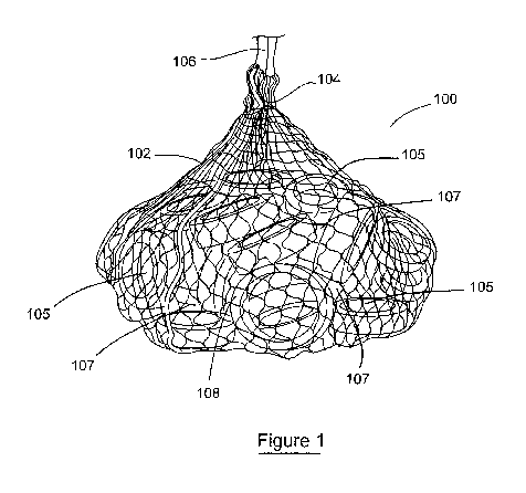
Referring now to Figure 1, there is provided a scour mitigation and
remediation
apparatus of the present disclosure, also, but not exclusively, referred to
herein as a
"scour remediation and mitigation apparatus" of the present disclosure, and
also
CA 02898649 2015-07-20
WO 2014/125127 PCT/EP2014/053159
- 15 -
known herein as an "anti-scour apparatus", indicated generally by reference
numeral
100. The scour remediation and mitigation apparatus 100 comprises a plurality
of
channelled members 108 housed within a flexible porous housing, such as net
bag
102. The plurality of channelled members 108 each comprising at least one
through
hole 105 and are loosely bound within the net bag 102. The arrangement of the
channelled members 108, each comprising at least one through hole 105, is such
that the plurality of channelled members 108 within the net bag 102 form a
plurality of
conduits through which water can be diverted and deflected. The conduits are
formed
by the through holes 105 which form the channels 105 in the channelled members
108 and by voids 107 between adjacent channelled members 108 in the net bag
102.
It is understood that the diversion and deflection of the currents of water
through the
scour remediation and mitigation apparatus 100 of the present disclosure
causes the
energy in the currents to be dissipated and this mitigates the scouring
effects of the
currents of water.
It will be understood that the channelled members 108 may be formed by any
shape
of object, where that object has a channel 105 passing through it. The size of
the
channel 105 passing through the channelled member 108 is important, as
discussed
in greater detail later, as this transmissivity of the channelled member 108
will ensure
that secondary scouring does not occur due to the channelled member. Most
preferably, the channel 105 is of sufficient dimension that a sphere of at
least twenty
centimetres can be passed through the channel 105 of an individual channelled
member prior to connection of such channelled member to other channelled
members and prior to incorporation of such channelled member into the
structure of
the present disclosure.
In a preferred embodiment, as can be seen throughout the Figures, the
channelled
members 108 in the scour remediation and mitigation apparatus 100 are used
tyres.
New tyres would of course be equally permissible to use, although the use of
used
tyres is commercially advantageous. These tyres are recycled and thus there is
an
environmental advantage to these old tyres which would otherwise have to be
recycled through a costly recycling process. The tyres may preferably be
washed and
cleaned of any unwanted grease, oil and dirt, prior to be arranged within the
net bag
102 to acts as the plurality of channelled members 108 in the scour
remediation and
CA 02898649 2015-07-20
WO 2014/125127 PCT/EP2014/053159
- 16 -
mitigation apparatus 100.
The scour remediation and mitigation apparatus 100 is constructed in the
following
manner. The scour remediation and mitigation apparatus 100 comprises an
opening
104 that is formed into the porous housing formed of the net bag 102 and which
is
securely closed after the scour remediation and mitigation apparatus 100 has
been
assembled by placing the plurality of channelled members 108 in the net bag
102. A
handling loop or handling rope 106 may be secured to the net bag 102 adjacent
the
opening 104. This facilitates the deployment and installation of the scour
remediation
and mitigation apparatus 100 on the seabed and also facilitates the recovery
of the
scour remediation and mitigation apparatus 100 from the seabed.
With reference to Figure 2, in order to assembly the scour remediation and
mitigation
apparatus 100, a portion of the plurality of channelled members 108A-108J are
arranged into a string 200 of channelled members. The portion of the plurality
of
channelled members 108A-108J are connected to one another using a rope 202.
The
rope 202 is preferably a laid, or twisted, rope.
Alternatively, the rope 202 may be a braided rope. In the preferred embodiment
shown in Figure 2, a 12mm polypropylene rope 202 has been used.
It has been found that the most effective way to connect the plurality of
channelled
members 108A-108J to one another is to pass the rope 202 through the through
hole
105 of a channelled member 108A, and then, after separating strands of the
rope
202, pass the rope 202 through the separated strands of the rope 202, and on
to the
next channelled member 108B, where the process is repeated until all of the
plurality
of channelled members 108A-108J are connected in series together and arranged
into the string 200 of channelled members. It will be readily understood that
the
channelled members 108A-108J may be connected by knotting the rope 202 rather
than separating strands of the rope 202. Moreover, the channelled members 108A-
108J could be connected using a plurality of individual ties, or by bolting
the
channelled members 108A-108J together, or by any other such joining means.
The string 200 may contain any number of channelled members108A-108J, but in a
CA 02898649 2015-07-20
WO 2014/125127 PCT/EP2014/053159
- 17 -
preferred embodiment, the string 200 will comprise ten channelled members 108A-
108J for ease of handling. A handling loop or handling rope length of
approximately
one metre may be provided for at one or both ends of the string 200 for ease
of
handling and lifting. Of course, different lengths of handling loop may be
provided, as
deemed appropriate. It will be understood that the channelled members 108A-
108J
do not have to be connected together in series although it is advantageous to
do so
from a handling point of view.
Referring now to Figures 3 and 4, during assembly of the scour remediation and
mitigation apparatus 100, the string 200 of the plurality of channelled
members 108 is
placed into the net bag 102. The net bag 102 may be held open within an
assembly
frame 300. The use of the assembly frame 300, which is substantially
cylindrical in
shape and is essentially an open ended drum, allows the string 200 of the
plurality of
channelled members 108 to be placed into the net bag 102. The opening of the
net
bag 102 is securely closed and the scour remediation and mitigation apparatus
100
can be lifted out of the assembly frame 300 by using the handling rope 106.
The plurality of channelled members 108 are arranged within the net bag 102
and
this creates a plurality of conduits through the scour remediation and
mitigation
apparatus 100 formed by the channels 105 in the channelled members 108 and by
the voids 107 between adjacent channelled members 108 in the net bag 102. It
is
understood that as tidal currents are deflected off a post at its base
adjacent the
seabed, the deflected currents, and in particular the kinetic energy within
these
currents, is dissipated as they are dispersed, diverted and deflected through
the
plurality of conduits in the scour remediation and mitigation apparatus 100.
This
dispersion, diversion and deflection has the result of mitigating against any
further
scour damage from been caused. The channelled members 108 are loosely bound
together and settle into a scoured hole (i.e. a cavity or depression having
been
formed into a seabed by the scouring action described supra) by acting as an
in-fill
for the scoured hole in the seabed, and thus remediating the scour effects
caused by
such currents. An important aspect of the use of the channelled members 108,
which
are tyres of other such object with similar transmissivity characteristics, is
that by
diverting and dispersing the kinetic energy of deflected tidal currents
through the
plurality of conduits in the scour remediation and mitigation apparatus 100,
the
CA 02898649 2015-07-20
WO 2014/125127 PCT/EP2014/053159
- 18 -
potential scour is mitigated and the secondary scouring is avoided. This is as
the
transmissivity of the channelled members 108 within the scour remediation and
mitigation apparatus 100 is such that the currents will flow through the
conduits
formed in the scour remediation and mitigation apparatus 100. The
transmissivity of
the scour remediation and mitigation apparatus 100 is an important feature of
the
present invention. Surprising, unexpectedly, contrary to the state of the art
and
against the trend in the industry and against the widely held beliefs in the
field the
scour mitigation and remediation apparatus of the present disclosure is
effective at
both mitigation of scour, and also at remediating scour by, when placed in a
scour
hole, resulting in the eventual refilling of such scour hole by naturally
occurring
sediment, concurrent with the retention of such refilled in naturally
occurring sediment
and mitigation of future scouring.
To further describe producing the scour mitigation, prevention and remediation
apparatus of the present: It will be understood that a plurality of strings
200 of
channelled members 108 may be placed in a single net 102. By using a plurality
of
strings 200 of, for example, ten channelled members 108, the handling of the
strings
200 is simplified. In order to fill a net having a volume of approximately
5m3, it has
been found that approximately fifty channelled members 108, in the form of
tyres, are
required. It is beneficial to allow space within the net after the channelled
members
108 have been added so that repositioning of the channelled members 108
underwater is relatively easily achievable so as to allow an installer to
create a
substantially flat surface if required. Thus, in the most preferable
embodiment, five
strings 200, each comprising ten channelled members 108A-108J, which are
tyres,
are placed into the net bag 102 to form the scour remediation and mitigation
apparatus 100. The weight of fifty channelled members 108A-108J in the form of
tyres in the scour remediation and mitigation apparatus 100 is approximately
425kg
on land, and will have a weight of approximately 80kg underwater when taking
the
buoyancy of the scour remediation and mitigation apparatus 100 into account.
This is a relatively light weight which is beneficial for deployment and
installation of
the scour remediation and mitigation apparatus 100; and, it is also beneficial
for the
recovery of the scour remediation and mitigation apparatus 100 from the
seabed.
CA 02898649 2015-07-20
WO 2014/125127 PCT/EP2014/053159
- 19 -
Furthermore, the risk of damaging underwater cabling and equipment during
deployment is minimised and the scour remediation and mitigation apparatus
100, in
some cases, can be deployed through dropping the scour remediation and
mitigation
apparatus 100 from a vessel and allowing the scour remediation and mitigation
apparatus 100 to sink to the seabed before final positioning is carried out by
an
underwater installer.
In use, and referring to Figure 5a, a scour remediation and mitigation
apparatus 100
is placed in a seabed hole or small trench in a seabed, which has been caused
by
scouring, in order to remediate the trench or hole, and furthermore to
mitigate against
the possibility of scouring occurring again. As can be seen with reference to
Figure
5b, it is envisaged that multiple scour remediation and mitigation apparatuses
100 will
typically be needed to fill most trenches or holes left by scouring which
occurs around
the bases of seabed structures 502. It is of course envisaged to use just a
single
scour remediation and mitigation apparatus 100 if the size of just one scour
remediation and mitigation apparatus 100 is appropriate for that particular
installation,
however normally a plurality of scour remediation and mitigation apparatuses
100 will
be required for each installation.
With reference to Figure 5a, the single scour remediation and mitigation
apparatus
100 is shown arranged within a small trench/hole which was created on a seabed
500. Throughout an installation, further scour remediation and mitigation
apparatuses
100 are placed adjacent the seabed structure 502 and on top of previously
installed
scour remediation and mitigation apparatuses 100 so that the trenches and
holes and
in-filled and a barrier to mitigate against future scouring is created, as
shown in
Figure 5b. The plurality of scour remediation and mitigation apparatuses 100
are
used to remediate any existing scour damage by in-filling any trenches or
holes
created by the scour damage, and also mitigate against further scour damage by
dissipating the energy in the currents which cause the scour damage.
Referring to Figure 5b, the scour remediation and mitigation apparatuses 100
are
flexible and malleable enough so as to substantially mould to the shape of the
trench
or hole in the seabed 500 so as to fill the trench or hole fully. The scour
remediation
and mitigation apparatuses 100 can be seen to be installed adjacent the
underwater
CA 02898649 2015-07-20
WO 2014/125127 PCT/EP2014/053159
- 20 -
seabed structure 502, which in this case is a pile for a turbine. In Figure
5a, a portion
of the underwater structure 502 can be seen to rise above a water level 504 of
the
body of water which is above the seabed 500.
Returning to Figure 5b, by placing a plurality of these scour remediation and
mitigation apparatuses 100 around the underwater structure 502 and on the
seabed
500 or on other scour remediation and mitigation apparatuses 100, an
installation of
scour remediation and mitigation apparatuses 100 is established which will
remediate
any scour damage about the underwater structure 502 by retaining seabed
particles
in the channels 105 and voids 107 created by and within the scour remediation
and
mitigation apparatuses 100; and, future scour damage is mitigated through the
dissipation of current energy by this installation by the scour remediation
and
mitigation apparatuses 100.
In a further embodiment, the scour remediation and mitigation apparatus may
comprise affixing means to allow each scour remediation and mitigation
apparatus
to be affixed to at least one other scour remediation and mitigation
apparatus. The
affixing means are preferably in the form of ties which extend outwardly from
the
net bag of the scour remediation and mitigation apparatus to act as the
affixing
means which allow the scour remediation and mitigation apparatus to be affixed
to
the at least one other scour remediation and mitigation apparatus. Such ties
are
shown in Figures 6 and 7 in respect of securing weights to the scour
remediation
and mitigation apparatuses, but it will be readily understood that the tie
could be
used to connect scour remediation and mitigation apparatuses together in an
installation.
Referring to Figures 6 and 7 together, yet a further embodiment of the scour
remediation and mitigation apparatus is provided and is indicated generally by
reference numeral 600. The scour remediation and mitigation apparatus 600
comprises means 606, 608 for connecting weights 602, 604 to the scour
remediation and mitigation apparatus 600. These weights 602, 604 may be
connected to the scour remediation and mitigation apparatus 600 to assist with
lowering the scour remediation and mitigation apparatus 600 towards a bed of a
body of water and/or maintaining the scour remediation and mitigation
apparatus
CA 02898649 2015-07-20
WO 2014/125127 PCT/EP2014/053159
- 21 -
600 in its installed location.
The weights 604, 606 may be therefore attached to the scour remediation and
mitigation apparatus 600 on land prior to installing the scour remediation and
mitigation apparatus 600, or, after the scour remediation and mitigation
apparatus
600 has been moved into location on a seabed. The net bag 102 of the scour
remediation and mitigation apparatus 600 comprises outwardly extending rope
ends 606, 608 which act as ties to allow these weights 602, 604 to be
connected to
the scour remediation and mitigation apparatus 600. In the embodiment shown in
Figures 6 and 7, additional tyres act as the weights 602, 604 and are attached
to
an exterior of the net bag 102 after they have been installed in position, or
on land,
prior to being installed. The additional tyres 602, 604 may preferably be
filled with a
weighted substance such as concrete although, this may not be necessary. These
external tyres will assist with remediating the scour damage, will act as
protection
of the nets as they are transported on land, and will also act as the weights
602,
604 on the scour remediation and mitigation apparatus 600.
In further embodiments not shown it will be readily appreciated that the
weights
602, 604 could alternatively be one or a combination of metals, stones and/or
concrete objects.
Examples of Presently Preferred Embodiments of the Present Disclosure
1. A scour remediation and mitigation apparatus (100) comprising a
plurality of
channelled members (108) whereby the channelled members (108) are bound
together to form the scour remediation and mitigation apparatus (100);
the plurality of channelled members (108) each comprising at least one
through hole (105) which forms a channel (105) through the channelled
member (108);
the plurality of channelled members (108) being bound together such that a
plurality of conduits are formed by the channels (105) of the channelled
members (108) and by voids (107) intermediate adjacent channelled
members (108) within the scour remediation and mitigation apparatus (100);
the plurality of conduits allowing passage of a moving fluid through the scour
remediation and mitigation apparatus (100) whilst simultaneously causing
CA 02898649 2015-07-20
WO 2014/125127 PCT/EP2014/053159
- 22 -
dispersion of kinetic energy of the moving fluid as it passes through the
scour
remediation and mitigation apparatus (100).
2. A scour remediation and mitigation apparatus (100) as described in
example
1, wherein, the channelled members (108) are bound together within a flexible
porous housing (102).
3. A scour remediation and mitigation apparatus (100) as described in
example
2, wherein, the flexible porous housing (102) is a net.
4. A scour remediation and mitigation apparatus (100) as described in
examples
2 or 3, wherein, the flexible porous housing (102) is a net bag.
5. A scour remediation and mitigation apparatus (100) as described in any
preceding examples, wherein, the plurality of channelled members (108) are
connected in series together.
6. A scour remediation and mitigation apparatus (100) as described in any
preceding examples, wherein, the plurality of channelled members (108) are
each connected to at least one other channelled member (108).
7. A scour remediation and mitigation apparatus (100) as described in any
preceding examples, wherein, the plurality of channelled members (108) are
connected together by a length of rope (202).
8. A scour remediation and mitigation apparatus (100) as described in
example
7, wherein, the length of rope (202) is preferably a length of laid rope.
9. A scour remediation and mitigation apparatus (100) as described in any
preceding examples, wherein, a portion of the plurality of channelled
members (108) are connected together into a string (200) of channelled
members (108), and each of the channelled members (108) in the string (200)
of channelled members (108) are only connected to other channelled
members (108) in said string (200) of channelled members (108).
CA 02898649 2015-07-20
WO 2014/125127 PCT/EP2014/053159
- 23 -
10. A scour remediation and mitigation apparatus (100) as described in
example
9, wherein, the plurality of channelled members (108) are arranged into a set
of distinct strings (200) of channelled members (108).
11. A scour remediation and mitigation apparatus (100) as described in
example
10, wherein, each distinct string (200) of channelled members (108)
comprises a substantially equal number of channelled members (108).
12. A scour remediation and mitigation apparatus (100) as described in any
preceding examples, wherein, the scour remediation and mitigation apparatus
(100) comprises affixing means (606) to allow each scour remediation and
mitigation apparatus (100) to be affixed to at least one other scour
remediation and mitigation apparatus (100).
13. A scour remediation and mitigation apparatus (100) as described in any
preceding examples, wherein, the remediation and mitigation apparatus (100)
comprises means (606, 608) for connecting weights to the scour remediation
and mitigation apparatus (100).
14. A scour remediation and mitigation apparatus (100) as described in
example
4, wherein, the net (102) of the scour remediation and mitigation apparatus
(100) comprises ties (606) which extend outwardly from the net bag to act as
affixing means to allow the scour remediation and mitigation apparatus (100)
to be affixed to at least one other scour remediation and mitigation apparatus
(100).
15. A scour remediation and mitigation apparatus (100) as described in
example
4, wherein, the net (102) of the scour remediation and mitigation apparatus
(100) comprises ties (606, 608) which extend outwardly from the net bag to
allow weights (602, 604) to be connected to the scour remediation and
mitigation apparatus (100).
16. A scour remediation and mitigation apparatus (100) as described in any
CA 02898649 2015-07-20
WO 2014/125127
PCT/EP2014/053159
- 24 -
preceding examples, wherein, the scour remediation and mitigation apparatus
(100) comprises a location transmitting beacon.
17. A scour remediation and mitigation apparatus (100) as described in any
preceding examples, wherein, the channelled members (108) have a specific
weight in the range of 1.05 to 2.
18. A scour remediation and mitigation apparatus (100) as described in any
of the
preceding examples, wherein, the channelled members (108) are torus in
shape.
19. A scour remediation and mitigation apparatus (100) as described in any
of the
preceding examples, wherein, the channelled members (108) are annular in
shape.
20. A scour remediation and mitigation apparatus (100) as described in any
of the
preceding examples, wherein, the channelled members (108) are made of a
rubber.
21. A scour remediation and mitigation apparatus (100) as described in any
of the
preceding examples, wherein, the channelled members (108) are rings having
a C-shaped cross-section.
22. A scour remediation and mitigation apparatus (100) as described in any
of the
preceding examples, wherein, the channelled members (108) are tyres.
23. A scour remediation and mitigation apparatus (100) suitable for
deployment
adjacent an underwater structure (502), the scour remediation and mitigation
apparatus (100) comprising a substantially monobloc body having a plurality
of through conduits arranged therein, each conduit branching off at least one
other conduit in the monobloc body so as to allow passage of a moving fluid
through the scour remediation and mitigation apparatus (100) whilst
simultaneously causing dispersion of kinetic energy of the moving fluid as it
passes through the conduits of the scour remediation and mitigation
CA 02898649 2015-07-20
WO 2014/125127 PCT/EP2014/053159
- 25 -
apparatus (100).
24. A scour remediation and mitigation apparatus (100) as described in
example
23, wherein, the scour remediation and mitigation apparatus (100) comprises
affixing means to allow each scour remediation and mitigation apparatus
(100) to be affixed to at least one other scour remediation and mitigation
apparatus (100).
25. A scour remediation and mitigation apparatus (100) as described in
example
23, wherein, the remediation and mitigation apparatus (100) comprises means
for connecting weights to the scour remediation and mitigation apparatus
(100).
26. A scour remediation and mitigation apparatus (100) as described in
example
23, wherein, the scour remediation and mitigation apparatus (100) comprises
ties which extend outwardly from the scour remediation and mitigation
apparatus (100) to act as affixing means to allow the scour remediation and
mitigation apparatus (100) to be affixed to at least one other scour
remediation and mitigation apparatus (100).
27. A scour remediation and mitigation apparatus (100) as described in
example
23, wherein, the scour remediation and mitigation apparatus (100) comprises
ties which extend outwardly from the scour remediation and mitigation
apparatus (100) to allow weights to be connected to the scour remediation
and mitigation apparatus (100).
28. A scour remediation and mitigation apparatus (100) as described in any
of
examples 23 to 27, wherein, the scour remediation and mitigation apparatus
(100) comprises a location transmitting beacon.
29. A scour remediation and mitigation apparatus (100) as described in any
of
examples 23 to 28, wherein, the scour remediation and mitigation apparatus
(100) has a specific weight in the range of 1.05 to 2.
CA 02898649 2015-07-20
WO 2014/125127 PCT/EP2014/053159
- 26 -
30. A scour
remediation and mitigation apparatus (100) as described in any of the
examples 23 to 29, wherein, the scour remediation and mitigation apparatus
(100) is made of a rubber.
31. A method of
protecting an underwater structure (502) against scour, by
installing a plurality of scour remediation and mitigation apparatuses (100),
as
described in any preceding examples, adjacent the underwater structure
(502), the method comprising the steps of:
-
lowering a first scour remediation and mitigation apparatus (100) into
position adjacent the underwater structure (502);
- lowering a second scour remediation and mitigation apparatus (100)
into position adjacent the underwater structure (502) and affixing it to
the first scour remediation and mitigation apparatus (100);
- lowering further scour remediation and mitigation apparatuses (100)
into positions adjacent the underwater structure (502) and affixing
them to at least one of the already lowered scour remediation and
mitigation apparatuses (100), until the underwater structure (502) is
protected against scour by the plurality of scour remediation and
mitigation apparatuses (100).
32. A method of
protecting an underwater structure (502) against scour as
described in example 31, wherein, the scour remediation and mitigation
apparatuses (100) are lowered using weights (606, 608).
33. A method of
protecting an underwater structure (502) against scour as
described in examples 31 or 32, wherein, the scour remediation and mitigation
apparatuses (100) are positioned during installation using location
transmitting
beacons.
34. A method of
protecting an underwater structure (502) against scour as
described in examples 31 or 33, wherein, weights (606, 608) are attached to
the scour remediation and mitigation apparatuses (100) after they have been
lowered into position.
CA 02898649 2015-07-20
WO 2014/125127 PCT/EP2014/053159
- 27 -
35. A method of protecting an underwater structure (502) against scour as
described in any of the examples 31 to 33, wherein, the scour remediation
and mitigation apparatuses (100) each comprise a plurality of tyres (108)
bound together in a net bag (102), with further tyres (602, 604) being affixed
to an exterior of the net bags (102) of at least a portion of the scour
remediation and mitigation apparatuses (100) after, or as, the portion of the
scour remediation and mitigation apparatuses (100) have been lowered into
position.
36. An anti-scour apparatus (100) for deployment in the vicinity of an
object
disposed in a body of water and in contact with a bed at the bottom of the
body of water, the anti-scour apparatus (100) comprising: a porous structure
having at least a plurality of cavities, at least some of the cavities having
at
least a wall and at least an open internal space, at least some of the
cavities
forming at least a portion of at least a through hole (105) that forms a
channel
(105), so that the anti-scour apparatus (100) includes a plurality of through
holes (105) forming a plurality of channels (105).
37. The anti-scour apparatus (100) of example 36 wherein at least some of
the
through holes (105) forming the plurality of channels (105) are able to have
positioned into at least a portion of at least some of the channels (105) an
entire sphere having a diameter of at least two centimetres.
38. The anti-scour apparatus (100) of example 36 wherein at least some of
the
through holes (105) forming the plurality of channels (105) are able to have
positioned into at least a portion of at least some of the channels (105) an
entire sphere having a diameter of at least four centimetres.
39. The anti-scour apparatus (100) of example 36 wherein at least some of
the
through holes (105) forming the plurality of channels (105) are able to have
positioned into at least a portion of at least some of the channels (105) an
entire sphere having a diameter of at least two centimetres.
40. The anti-scour apparatus (100) of example 36 wherein at least some of
the
CA 02898649 2015-07-20
WO 2014/125127 PCT/EP2014/053159
- 28 -
through holes (105) forming the plurality of channels (105) are able to have
positioned into at least a portion of at least some of the channels (105) an
entire sphere having a diameter of at least five centimetres.
41. The anti-scour apparatus (100) of example 36 wherein at least some of
the
through holes (105) forming the plurality of channels (105) exhibit a width of
at
least five centimetres measured across at least a portion of at least some of
the channels (105).
42. The anti-scour apparatus (100) of example 36 wherein at least some of
the
through holes (105) forming the plurality of channels (105) exhibit a width of
at
least seven centimetres measured across at least a portion of at least some
of the channels (105).
43. The anti-scour apparatus (100) of example 36 wherein at least some of
the
through holes (105) forming the plurality of channels (105) exhibit a width of
at
least eleven centimetres measured across at least a portion of at least some
of the channels (105).
44. The anti-scour apparatus (100) of example 36 wherein at least some of
the
through holes (105) forming the plurality of channels (105) exhibit a width of
at
least fifteen centimetres measured across at least a portion of the at least
some of the channels (105).
45. The anti-scour apparatus (100) of example 36 wherein at least some of
the
through holes (105) forming the plurality of channels (105) exhibit a width of
at
least seventeen centimetres measured across at least a portion of at least
some of the channels (105).
46. The anti-scour apparatus (100) of example 36 wherein at least some of
the
through holes (105) forming the plurality of channels (105) exhibit a width of
at
least twenty-one centimetres measured across at least a portion of at least
several of the channels (105).
CA 02898649 2015-07-20
WO 2014/125127 PCT/EP2014/053159
- 29 -
47. The anti-scour apparatus (100) of example 36 wherein at least some of
the
through holes (105) forming the plurality of channels (105) exhibit a width of
at
least twenty-six centimetres measured across at least a portion of at least
several of the channels (105).
48. The anti-scour apparatus (100) of any of the above examples where the
anti-
scour apparatus (100) exhibits a weight in air that is less than seventy
percent
of a weight in air of a conventional and previously known scour remediation
and mitigation structure formed of cement blocks.
49. The anti-scour apparatus (100) of any of the above examples where the
anti-
scour apparatus (100) exhibits a weight in air that is less than sixty percent
of
a weight in air of a conventional and previously known scour remediation and
mitigation structure formed of cement blocks.
50. The anti-scour apparatus (100) of any of the above examples where the
anti-
scour apparatus (100) exhibits a weight in air that is less than sixty percent
of
a weight in air of a conventional and previously known scour remediation and
mitigation structure formed of a stone bag, where the anti-scour apparatus
(100) and the stone bag are of similar size.
51. The anti-scour apparatus (100) of any of the above examples where the
anti-
scour apparatus (100) exhibits a weight in air that is less than fifty percent
of a
weight in air of a conventional and previously known scour remediation and
mitigation structure formed of a stone bag, where the anti-scour apparatus
(100) and the stone bag are of similar size.
It is further envisaged that a location transmitting beacon, for example which
could
use the Global Positioning System (GPS), is connected to each of the scour
remediation and mitigation apparatuses and is used to detect the co-ordinates
of
the scour remediation and mitigation apparatus. These co-ordinates are then
relayed to a remote monitoring station where the precise location of each
scour
remediation and mitigation apparatus can be assessed and monitored to ensure
that the scour remediation and mitigation apparatus is in the correctly
installed
CA 02898649 2015-07-20
WO 2014/125127 PCT/EP2014/053159
- 30 -
location and has not moved over time due to tidal and current effects.
For commercial reasons, the use of tyres as the channelled members within the
net
bag is very advantageous. It is intended that any size of tyre may be used,
although
the tyres will advantageously be used car tyres. Tyre-like objects may also be
specifically manufactured and used for this particular purpose. By using any
type of
tyre, there is no need to sort and select any tyres which simplifies the scour
remediation and mitigation apparatus assembly procedure. Tyres are also
advantageously used as the weights although it will be appreciated that they
perform
a different function to the tyre acting as channelled members within the net
bag.
The flexible porous housing, i.e. the net, net bag, or netting 102 may
preferably be
meshed twin stretched knot net bag, with a volume of 5m3. Of course, any
suitably
sized net bag may be used.
It will also be understood that at the crux of the present disclosure is the
remediation
of scour damage and dissipation of the energy of the currents through a
plurality of
conduits. Therefore, it will be readily understood that a monobloc body having
a
number of energy dissipating conduits running through it would provide the
same
technical advantage as the preferred embodiment of a scour remediation and
mitigation apparatus which comprises a plurality of tyres within a net bag.
However, it
will be understood that such a monobloc scour remediation and mitigation
apparatus
would not be capable of deforming into a trench, or hole, in the same manner
as a
plurality of tyres within a net bag. However, these types of monobloc scour
remediation and mitigation apparatus could be useful for protection of harbour
walls,
shorelines and the like by installing a row of such monobloc scour remediation
and
mitigation apparatuses in front of the shoreline.
Throughout this specification, the present disclosure has been directed
towards the
remediation of scour damage and the prevention or minimisation of further
scouring
from occurring on the seabed. However, it will be readily understood that the
method
and apparatus are equally applicable to the remediation and
prevention/minimisation
of scouring on riverbeds and other bodies of water where currents, which lead
to
scouring, are to be found.
CA 02898649 2015-07-20
WO 2014/125127 PCT/EP2014/053159
- 31 -
The present disclosure will thusly be also understood to be directed towards a
simple
and effective method for remediating and preventing, or at least minimising,
scour
from occurring on river banks, inland waterways, canal banks and revetments on
such banks. The scour remediation and mitigation apparatus of the present
disclosure can be used as in-fill to repair such damaged banks and revetments
and
further minimise the chance of future scouring damage. The scour remediation
and
mitigation apparatus can be used as a core with local sand, shingle or other
such in-
fill material.
It will be readily appreciated that the sizes, weights and volumes of the
scour
remediation and mitigation apparatus described hereinbefore may be changed
without departing from the inventive concept of the present disclosure The
sizes,
weights and volumes hereinbefore mentioned should therefore not be taken as
-- limiting the present disclosure in any manner.
It will be understood that in some scenarios the remediation and mitigation
apparatus
of the present disclosure will mitigate scour so effectively as to completely
prevent
scour from occurring.
It will be understood that any reference to an "underwater structure" or
"seabed
structure" shall refer to a structure which comprises a portion of the
structure beneath
the surface of a body of water, and adjacent to or in contact with and or in
abutment
with a bed of a body of water. The body of water could be an ocean, a sea, a
lake, a
-- river or any types of body of water whose bed is susceptible to scouring.
The
structure may not be entirely submerged and indeed in many cases the
underwater
structures referred to in the preceding specification shall comprise a portion
of the
structure beneath a water level and a portion of the structure above the water
level.
-- The terms "comprise" and "include", and any variations thereof required for
grammatical reasons, are to be considered as interchangeable and accorded the
widest possible interpretation.
It will be understood that the components shown in any of the drawings are not
CA 02898649 2015-07-20
WO 2014/125127 PCT/EP2014/053159
- 32 -
necessarily drawn to scale, and, like parts shown in several drawings are
designated
the same reference numerals.
The present disclosure is not limited to the embodiments hereinbefore
described
which may be varied in both construction and detail.