Note: Descriptions are shown in the official language in which they were submitted.
CA 02898743 2015-07-20
WO 2014/116724 PCT/US2014/012579
GAS JET INJECTOR REACTOR FOR CATALYTIC FAST PYROLYSIS
Terry Mazanec, Jeff Whiting, Roger Song, Zachary Goodman, Collin Schmidt
FIELD OF INVENTION
This invention relates to methods for the production of biochemicals such as
biofuel,
aromatics, and olefin compounds, and more specifically, to process feed
methods, systems, and
apparatus for the production of fuels and chemicals via catalytic fast
pyrolysis.
RELATED APPLICATIONS
This application claims the benefit of the priority of United States
Provisional Patent
Application Ser. No. 61/755358, filed 22 January 2013.
BACKGROUND
Biomass upgrading requires the feeding of a variety of particulate solid
materials such as
wood chips, sawdust, yard waste, cuttings, other vegetation; agricultural
products and
agricultural waste (e.g., corn stover, bagasse, fruit, garbage, silage, etc.);
energy crops (e.g.
switchgrass, miscanthus); algae and other marine plants; metabolic wastes
(e.g., manure,
sewage); and cellulosic urban waste etc., to a fluidized bed of catalyst for
catalytic fast pyrolysis.
Partially upgraded or converted biomass, such as pyrolysis oils,
carbohydrates, digestion
products or the like, that are often liquids or semi-solids, could also be
used in the process, either
alone or in combination with solid feeds.
Catalytic fast pyrolysis process (CFP) of biomass requires the conversion of a
variety of
high molecular weight materials such as lignin, cellulose, and hemi-cellulose,
by pyrolysis in the
presence of a catalyst, preferably an acidic, micro-porous catalyst, usually a
zeolite. The zeolite
1
CA 02898743 2015-07-20
WO 2014/116724 PCT/US2014/012579
is active for the upgrading of the primary pyrolysis products of biomass
decomposition, and
converts them to aromatics, olefins, CO/CO2, char, coke, water, and other
useful materials.
For the catalytic fast pyrolysis process (CFP) to be effective biomass must
not be heated
above the temperature at which pyrolysis begins, typically about 150-200 C,
before it is in the
vicinity of the catalyst to maximize the interaction of the primary pyrolysis
products with the
catalyst for conversion to aromatics, olefins and other useful materials. At
the same time, when
the biomass is heated, it must be heated very rapidly, at heating rates as
much as 500 C/sec, to
minimize formation of char and maximize the production of useful materials.
Thus, a problem in
the fast pyrolysis and catalytic fast pyrolysis of biomass is how to introduce
the biomass feed
into the pyrolysis reactor, keeping it from heating prematurely in the feed
line where char can
form and yet heating it very rapidly once it enters the reaction zone.
Screw auger feed devices have been used to feed the biomass to fluidized bed
reactors, but
the linear flow rate of the biomass is relatively slow in the feed auger, so
the biomass can be
heated as it approaches the hot catalyst bed, resulting in char formation and
low yields of
aromatics and olefins. Premature partial pyrolysis of the biomass also
releases oily intermediates
that can clog the movement of the auger. Scale up of the auger feed system is
problematic as
well since an auger that extends into the center of a large reactor would
necessarily become quite
hot or would require cooling that wastes heat and cools the reactor bed. The
present invention
overcomes the problems involved in feeding biomass into a hot, fast pyrolysis
or hot, catalytic
fast pyrolysis reactor by use of a gas jet to feed the biomass into the fluid
bed.
In US 6105275, a continuous rotary vacuum retort apparatus and its use are
described. The
patent mentions the use of elastomeric pinch valves used to create an airlock
in a vacuum retort
but not operation under elevated pressures or as feed system for a catalyzed
fluid bed. In EP
2
CA 02898743 2015-07-20
WO 2014/116724 PCT/US2014/012579
0075899, a process for transferring solids is described in which a gas is used
as a barrier for
metering of solids between two pressure controlled vessels. In EP 0820419 Bl,
an air lock for
pneumatic conveyance and separation of solids from the conveying air is
described that employs
a rotary airlock for removing solids from conveying airstream. In WO
1996018564 B I, a
vertical-shaft airlock is described that uses rotating mechanical seals. In WO
2013095163 Al, a
continuous pyrolysis apparatus is described wherein pyrolysis occurs on an
auger with material
admitted and expelled by use of airlocks. No airlock structure specified
beyond 'valves'. In US
20130019492, a system for the continuous treatment of solids at non-
atmospheric pressure is
described using a semi-batch airlock that is loaded with enough material to
continuously supply a
process prior to being reloaded as in a typical lock-hopper system.
Asadullah et al., in "Biomass Gasification to Hydrogen and Syngas at Low
Temperature:
Novel Catalytic System Using Fluidized-Bed Reactor," J. Catal. 208, 255-259
(2002), described
an experimental combustion system in which cellulose was continuously
transported into a
fluidized catalyst bed through a 5 mm outlet in a feed hopper by the flow of
N2 gas through an
inner tube of 5 mm inner diameter into a concentric tube of 18 mm inner
diameter containing a
catalyst bed containing Rh/Ce02/Si02 catalyst. The cellulose was converted to
hydrogen and
CO.
Eastham et al. in US 5968460 and US 5175943 describe methods of continuously
adding
solids to a combustion process conducted in a fluidized bed from a standpipe
having an angle
that has a bend to hold back the solids. The standpipe contains gas inlets to
maintain the pressure
slightly above that in the fluidized bed. The gases added to the standpipe can
be used to fluidize
the solids in the standpipe and lessen the binding of particles.
3
CA 02898743 2015-07-20
WO 2014/116724 PCT/US2014/012579
Medoff in US 2012/0094355 describes a noncatalytic process in which
pressurized gases
can be added to a biomass-derived feedstock stream to propel the feedstock
into a pyrolysis
chamber to produce sugars or amino acids.
Jones, in US 4474119 discloses a fluidized bed combustion furnace in which
coarse
limestone is added through a nozzle into the fluidized bed and solid fines are
added along with
the fluidization fluid. The fine feed solids can be added tangentially.
Rozainee et al., in "Effect of Feeding Methods on the Rice Husk Ash Quality in
a
Fluidised Bed Combustor," Emirates J. Eng. Res., 15, 1-12 (2010), reported the
results of a study
in which rice husks are fed by gas injection into a fluidized bed combustion
chamber from an
inlet inclined at a 45 angle. The ash produced in the combustion when feed
entered the reaction
chamber from a tangentially disposed inlet was reported to be smaller particle
size and lower
carbon content than ash produced with radial feed.
North et al. (Nova Pangea Technologies) in US Patent Appl 20110100359
describes a5-
step process that includes entraining biomass solids in a flow of superheated
steam in a steam
loop to cause the cells to explode prior to introduction of the biomass in a
hydrolysis reactor and
condensation of the hydrolyzed sugar-containing materials. Zielinski et al. in
US 4309948
describe delivery of an entrained stream of carbonaceous solid particles to a
catalyst bed through
a mushroom-shaped cap. Wachter in US 5688472 describes using a downward flow
of gas
through an annulus to fluidize a reactor bed. Klajay et al. in US 2012/0251959
disclose a
fluidized bed fuel feed system that introduces the solid fuel along a channel
in the wall into a
grid section to increase the time of the heatup of the fuel to dry the fuel,
i.e., reduce the rate of
heating, before it enters the turbulent fluid bed. Bartek in US 8523496
describes a process for
feeding biomass to a reactor for conversion to oxygenated hydrocarbons that
utilizes a spool
4
CA 02898743 2015-07-20
WO 2014/116724 PCT/US2014/012579
piece adapted to convey solids from a lower pressure to a higher pressure;
however, other than
increasing pressure, no steps are taken to control injection conditions or
reduce preheating of the
biomass..
Thus a need exists for a process and apparatus for feeding biomass to a fluid
bed or similar
reactor that minimizes premature heating of the biomass and mixes it rapidly
with the materials
in the reactor.
SUMMARY OF THE INVENTION
The present invention comprises a novel feed system for introducing biomass
into a
pyrolysis reactor, such as a catalytic fast pyrolysis (CFP) fluid bed reactor,
that employs a jet
stream of gas or vapor to inject the biomass particles into the fluid bed. The
biomass is kept
relatively cool, can be metered upstream of a gas jet, and can be injected far
into the fluid bed.
Good mixing between the relatively cooler biomass with the hot catalyst and
other materials in
the fluid bed can be insured by adjustment of the number, size, angle,
position, and flow rate of
the multiple injector ports in larger reactors. The invention may further
comprise an automated
feed metering system comprising pinch valves and a holding tank that allows
operation of the
CFP process at higher pressure while allowing the feed to be maintained at
lower pressures and
injects the biomass in discrete portions that penetrate further into the
reactor enhancing mixing
and rapid heating of the biomass.
In a first aspect, the invention provides a method for producing one or more
fluid
hydrocarbon products from a solid hydrocarbonaceous material comprising:
feeding a first
reactant comprising the solid hydrocarbonaceous material to a reactor by
injection in a gas jet;
pyrolyzing within the reactor at least a portion of the hydrocarbonaceous
material under reaction
conditions sufficient to produce one or more pyrolysis products; and
catalytically reacting at
least a portion of the one or more pyrolysis products under reaction
conditions sufficient to
produce the one or more fluid hydrocarbon products; and further comprising one
or more of the
following characteristics: wherein the gas jet comprises a carrier fluid and
the solid
hydrocarbonaceous material, wherein the gas jet enters the reactor through a
feed port and
wherein the carrier fluid flows through the feed port with a linear velocity
of at least 25 cm/sec;
5
CA 02898743 2015-07-20
WO 2014/116724 PCT/US2014/012579
or wherein the solid hydrocarbonaceous material is feed though a feed port
into a fluidization
reactor with a ratio of gas flow rate through the feed port to flow through a
fluidization port of
less than 10; or wherein the solid hydrocarbonaceous material is fed into the
reactor through a
feed port wherein the feed port has an angle that is at least 15 degrees from
the horizontal.
In some preferred aspects, the linear velocity of the carrier fluid in the
feed port is at least
25 cm/sec, 50 cm/sec, 100 cm/sec, 150 cm/sec, or at least 200 cm/sec, or at
least 225 cm/sec, or
at least 250 cm/sec, or at least 300 cm/sec, or from 25 cm/sec to 10,000
cm/sec, or from 50 to
7,000 cm/sec, or from 100 to 5,000 cm/sec, or from 200 to 5,000 cm/sec, or
from 225 to 5,000
cm/sec.
In some preferred aspects, the ratio of gas flow rate injected with the solid
hydrocarbonaceous material to the gas flow rate introduced through the
fluidization port is less
than 0.1, less than 0.25, less than 0.5, less than 1, less than 2, less than
3, less than 5, or less than
10. In some preferred embodiments, the space velocity of the biomass in
comparison to the
catalyst contained in the reactor is at least 0.1, at least 0.2, at least 0.3,
at least 0.4, at least 0.5, at
least 0.8, or at least 1.0, or from 0.1 to 2Ø
An advantage of the inventive methods and systems is improved yield of
aromatics;
preferably the carbon percent yield of aromatics plus olefins is at least 15%.
at least 20%, at least
25%, at least 30%, or at least 35%. In some preferred embodiments, the carbon
percent yield of
para- and meta-xylene is at least 0.5%, at least 1.0%, at least 1.5%, at least
2.0%, or at least
2.5%. In some preferred embodiments, the carbon percent yield of methane is
less than 10%, less
than 5%, less than 4%, less than 3%, less than 2% or less than 1.5%.
In some preferred embodiments, the fluidization gas residence time in contact
with the
catalyst bed is at least 0.1, at least 0.2, at least 0.3, at least 0.5, at
least 0.7, at least 1.0, at least
2.0,at least 3.0 seconds, or at least 5.0 seconds, or at least 10.0 seconds,
or at least 20 seconds,
and in some embodiments less than 60 seconds. or less than 40 seconds.
In some aspects, catalyst is fed in a continuous or semi-continuous manner to
the reactor
and catalyst is withdrawn in a continuous or semi-continuous manner from the
reactor.
In some preferred embodiments, the solid hydrocarbonaceous material is fed
into the
reactor through a feed port wherein the feed port has an angle that is at
least 15 degrees, at least
25 degrees, at least 35 degrees, at least 45 degrees, at least 50 degrees, or
at least 62 degrees
6
CA 02898743 2015-07-20
WO 2014/116724 PCT/US2014/012579
from the horizontal at the point at which it enters the reactor, where the
maximum angle of the
feed port is about 900
.
In some preferred embodiments, a gas for the gas jet is carried through a
carrier flow tube
that carries the gas into the feed, and wherein the angle that the carrier
flow tube makes with the
horizontal is greater than the angle at which the biomass feed tube enters the
pyrolysis reactor,
both being positive values.
In some embodiments, the ratio of gas flow rate injected with the solid
hydrocarbonaceous material biomass to the gas flow rate introduced through the
fluidization port
is between 0.001 and 10, or between 0.01 and 5, or between 0.1 and 2.
In some embodiments, the solid hydrocarbonaceous material is fed in
discontinuous
pulses in the gas feed. In some preferred embodiments, the frequency of the
pulses of solid
hydrocarbonaceous material fed from any one feed port is in the range from
once every 0.2
seconds to one pulse every 60 seconds. In some embodiments, the duration of
flow during an
individual pulse from a single feed port is between 0.05 seconds and 30
seconds in length.
In another aspect, the invention provides a system for producing one or more
fluid
hydrocarbon products from a hydrocarbonaceous material comprising a pyrolysis
zone into
which a solid hydrocarbonaceous material is introduced by injection in a
flowing gas stream,
a solid catalyst is introduced, and at least a portion of the
hydrocarbonaceous material pyrolyzes
and catalytically reacts under reaction conditions sufficient to produce one
or more pyrolysis
products. This system may be further characterized by one or more of the
characteristics
described above with respect to the first aspect. Preferably, the solid
hydrocarbonaceous material
is introduced by the injection in a flowing gas stream into a reactor
comprising a fluidized bed,
and wherein, prior to introduction to the fluidized bed, the hydrocarbonaceous
material is
maintained at a temperature less than 300 C, or less than 200 C or less than
150 C, or less than
100 C, or maintained with a range of temperatures from 20 C to 300 C, 20 C
to 200 C, 20
C to 150 C, or 20 C to 100 C (as with other features described herein,
these temperature
ranges also apply to preferred embodiments of the methods and operation of the
apparatus; the
invention can also be characterized as having these temperature ranges in the
feed tube, and
preferably in combination with the absence of a screw auger since a screw
auger can increase
temperature in the feed tube). In some preferred embodiments, the solid
hydrocarbonaceous
7
CA 02898743 2015-07-20
WO 2014/116724 PCT/US2014/012579
material is fed into the reactor through a feed port wherein the feed port has
an angle that is at
least 15 degrees, at least 25 degrees, at least 35 degrees, at least 45
degrees, at least 50 degrees,
or at least 62 degrees from the horizontal at the point at which it enters the
reactor, where the
maximum angle of the feed port is about 900
.
Any of the features discussed with respect to the methods may also be
incorporated into
the inventive systems. For example, similar to what is discussed above, a gas
for the us jet can
be carried through a carrier flow tube that carries the gas into the feed, and
wherein the angle that
the carrier flow tube makes with the horizontal is greater than the angle at
which the biomass
feed tube enters the pyrolysis reactor, both being positive values. The solid
hydrocarbonaceous
material is fed in discontinuous pulses in the gas feed. The frequency of the
pulses of solid
hydrocarbonaceous material fed from any one feed port is in the range from
once every 0.2
seconds to one pulse every 60 seconds. In some embodiments, the duration of
flow during an
individual pulse from a single feed port is between 0.05 seconds and 30
seconds in length.
In another aspect, the invention provides an apparatus for producing one or
more fluid
hydrocarbon products from a hydrocarbonaceous material, which apparatus
comprises in
combination: a pyrolysis reaction chamber; at least one feed tube by which
solid
hydrocarbonaceous material may be introduced by gas-assisted injection into
the pyrolysis
reaction chamber, wherein the angle a of the feed port is at least 15 degrees
from the horizontal;
a delivery structure by which solid catalyst may be introduced therein; a
fluidization gas inlet
line connecting with a lower portion of said reaction chamber for introducing
a fluidization gas;
a catalyst exit conduit; and a product exit conduit from which vapor phase
products may exit the
reactor. In some preferred embodiments, the angle a of the feed port is at
least 25 degrees, at
least 35 degrees, at least 45 degrees, at least 50 degrees, or at least 62
degrees from the
horizontal, where the maximum angle of the feed port is about 90 . Delivery
structures for
delivering catalyst to pyrolysis reactors are known in the art. In some
preferred embodiments, the
apparatus further comprises a carrier flow tube that is adapted to carry the
gas into the feed, and
wherein the angle that the carrier flow tube makes with the horizontal is
greater than the angle at
which the biomass feed tube enters the pyrolysis reactor, both being positive
values.
In some preferred embodiments, a delivery structure by which a solid catalyst
may be
introduced to the pyrolysis reaction chamber comprises a tube containing
catalyst particles.
8
CA 02898743 2015-07-20
WO 2014/116724 PCT/US2014/012579
In preferred embodiments, during operation of the apparatus, prior to
introduction to the
fluidized bed, the hydrocarbonaceous material is maintained at a temperature
less than 300 C, or
less than 200 C or less than 150 C. or less than 100 C, or maintained with
a range of
temperatures from 20 C to 300 C, 20 C to 200 C, 20 C to 150 C, or 20 C
to 100 C.
In a further aspect, the invention provides a method or system for producing
one or more
fluid hydrocarbon products from a solid hydrocarbonaceous material comprising:
feeding a first
reactant comprising the solid hydrocarbonaceous material to a fluidized bed
reactor comprising a
distributor by injection of the solid material in a gas jet or gas jets
through a port or ports,
wherein the carrier gas in the gas jet is at a temperature of less than 200
C, to form a gas
mixture comprising suspended solid particles in a lower section of the reactor
that has a
normalized temperature in the range of 100 to 600 C; pyrolyzing within an
upper section of the
reactor at least a portion of the gas mixture comprising suspended solid
particles in a catalyzed
reaction at a temperature of at least 500 C to produce one or more pyrolysis
products; wherein
the upper section is above the lower section with respect to gravity; wherein
the lower section
comprises a volume that includes an inner diameter of the fluidized bed
reactor and a height that
is at least 2% of the total reactor height, and wherein the upper section
comprises a volume that
includes an inner diameter of the fluidized bed reactor and a height that is
at least 5% of the total
reactor height; wherein the lower and upper sections are both above the
distributor. Preferably,
the method or system further comprises feeding a fluidizing gas into the lower
section. Also,
preferably, the fluidizing gas passes through a distributor prior to entering
the lower section. In
some embodiments, the lower section does not contain any catalyst trays and
the upper section
comprises at least one catalyst tray. In some embodiments, the lower section
contains less than
10 wt% of the total catalyst in the reactor and the upper section comprises at
least 50 wt% of the
total catalyst in the reactor. In some embodiments, the upper section has a
temperature in the
range of 500 C to 800 C.
In a further aspect, the invention provides a system for producing one or more
fluid
hydrocarbon products from a solid hydrocarbonaceous material comprising: a
fluidized bed
reactor comprising a lower section and an upper section; wherein the lower
section comprises a
gas mixture and suspended biomass solids, wherein the gas mixture is in a
temperature range of
100 to 400 C (preferably 200 to 350 C); and wherein the upper section
comprises a suspension
of catalyst particles and fully or partially pyrolyzed biomass and wherein the
upper section
9
CA 02898743 2015-07-20
WO 2014/116724 PCT/US2014/012579
comprises a temperature of at least 500 C. Preferably, the lower section is
disposed immediately
above a distributor and the lower section comprises a gas injector inlet
through which a gas
carrying biomass is introduced and wherein a fluidizing gas that does not
contain biomass passes
through the distributor and forms a mixture with the gas carrying the biomass
that flows into the
reactor through the gas injector.
It should be understood that the descriptions herein are to be read broadly
and any of the
methods, apparatus and systems may incorporate any of the features discussed
throughout this
specification.
Glossary
Aromatics - As used herein, the terms "aromatics" or "aromatic compound" are
used to refer to a
hydrocarbon compound or compounds comprising one or more aromatic groups such
as, for
example, single aromatic ring systems (e.g., benzyl, phenyl, etc.) and fused
polycyclic aromatic
ring systems (e.g. naphthyl, 1,2,3,4-tetrahydronaphthyl, etc.). Examples of
aromatic compounds
include, but are not limited to, benzene, toluene, indane, indene, 2-ethyl
toluene, 3-ethyl toluene,
4-ethyl toluene, trimethyl benzene (e.g., 1,3,5-trimethyl benzene, 1,2,4-
trimethyl benzene, 1,2,3-
trimethyl benzene, etc.), ethylbenzene, styrene, cumene, methylbenzene,
propylbenzene, xylenes
(e.g., p-xylene, m-xylene, o-xylene), naphthalene, methyl-naphthalene (e.g., 1-
methyl
naphthalene. anthracene, 9.10-dimethylanthracene, pyrene, phenanthrene, di
methyl-naphthalene
(e.g., 1.5-dimethylnaphthalene, 1,6-dimethylnaphthalene, 2,5-
dimethylnaphthalene, etc.), ethyl-
naphthalene, hydrindene, methyl-hydrindene, and dymethyl-hydrindene. Single-
ring and/or
higher ring aromatics may also be produced in some embodiments. Aromatics also
include single
and multiple ring compounds that contain heteroatom substituents, ie phenol,
cresol, benzofuran,
etc.
Biomass - As used herein, the term "biomass" is given its conventional meaning
in the art and is
used to refer to any organic source of energy or chemicals that is renewable.
Its major
components can be: (1) trees (wood) and all other vegetation; (2) agricultural
products and
wastes (corn, fruit, garbage ensilage, etc.); (3) algae and other marine
plants; (4) metabolic
wastes (manure, sewage), and (5) cellulosic urban waste. Examples of biomass
materials are
CA 02898743 2015-07-20
WO 2014/116724 PCT/US2014/012579
described, for example, in Huber, G.W. et al, "Synthesis of Transportation
Fuels from Biomass:
Chemistry, Catalysts, and Engineering," Chem. Rev. 106, (2006). pp. 4044-4098.
Biomass is conventionally defined as the living and recently dead biological
material that can be
converted for use as fuel or for industrial production. The criterion for
biomass is that the
material should be recently participating in the carbon cycle so that the
release of carbon in the
combustion process results in no net increase averaged over a reasonably short
period of time
(for this reason, fossil fuels such as peat, lignite and coal are not
considered biomass by this
definition as they contain carbon that has not participated in the carbon
cycle for a long time so
that their combustion results in a net increase in atmospheric carbon
dioxide). Most commonly,
biomass refers to plant matter grown for use as biofuel, but it also includes
plant or animal matter
used for production of fibers, chemicals or heat. Biomass may also include
biodegradable wastes
or byproducts that can be burnt as fuel or converted to chemicals, including
municipal wastes,
green waste (the biodegradable waste comprised of garden or park waste, such
as grass or flower
cuttings and hedge trimmings), byproducts of fanning including animal manures,
food
processing wastes, sewage sludge, black liquor from wood pulp or algae.
Biomass excludes
organic material which has been transformed by geological processes into
substances such as
coal, oil shale or petroleum. Biomass is widely and typically grown from
plants, including
miscanthus, spurge, sunflower, switchgrass, hemp, corn (maize), poplar,
willow, sugarcane, and
oil palm (palm oil) with the roots, stems, leaves, seed husks and fruits all
being potentially
useful. The particular plant or other biomass source used is not important to
the product chemical
or fuel although the processing of the raw material for introduction to the
processing unit will
vary according to the needs of the unit and the form of the biomass.
Biomass-derived - Any of the products, processes, and/or systems described
herein may be
additionally characterized by the fact that they are biomass-derived, meaning
that the products
are at least partly derived from biomass, and, in most cases are 100% or
nearly 100% derived
from biomass. As is well-known, the presence of biomass-derived material can
be readily
ascertained by the presence of 14C, which is present in significantly lower
concentrations in
fossil fuels.
11
CA 02898743 2015-07-20
WO 2014/116724 PCT/US2014/012579
Biomass Pyrolysis Liquid - Biomass pyrolysis liquid or bio-oil is the liquid
fraction that can be
isolated from a pyrolysis reaction of biomass. Biomass pyrolysis liquid is
usually dark brown
and approximates to biomass in elemental composition. It is composed of a very
complex
mixture of oxygenated hydrocarbons with an appreciable proportion of water
from both the
original moisture and reaction product. Compositionally, the biomass pyrolysis
oil will vary with
the type of biomass, but is known to consist of oxygenated low molecular
weight alcohols (e.g.,
furfuryl alcohol), aldehydes (aromatic aldehydes), ketones (furanone), phenols
(methoxy
phenols) and water. Solid char may also be present, suspended in the oil. The
liquid is formed by
rapidly quenching the intermediate products of flash pyrolysis of
hemicellulose, cellulose and
lignin in the biomass. Chemically, the oil contains several hundred different
chemicals in widely
varying proportions, ranging from formaldehyde and acetic acid to complex,
high molecular
weight phenols, anhydro sugars and other oligosaccharides. It has a
distinctive odor from low
molecular weight aldehydes and acids, is usually acidic with a pH of 1.5-3.8,
and can be an
irritant.
Catalysts - Catalyst components useful in the context of this invention can be
selected from any
catalyst known in the art, or as would be understood by those skilled in the
art. Catalysts promote
and/or effect reactions. Thus, as used herein, catalysts lower the activation
energy (increase the
rate) of a chemical process, and/or improve the distribution of products or
intermediates in a
chemical reaction (for example, a shape selective catalyst). Examples of
reactions that can be
catalyzed include: dehydration, dehydrogenation, isomerization, hydrogen
transfer,
aromatization, decarbonylation, decarboxylation, aldol condensation,
polymerization, and
combinations thereof. Catalyst components can be considered acidic, neutral or
basic, as would
be understood by those skilled in the art.
For fast catalytic pyrolysis, particularly advantageous catalysts include
those containing internal
porosity selected according to pore size (e.g., mesoporous and pore sizes
typically associated
with zeolites), e.g., average pore sizes of less than about 100 Angstroms,
less than about 50
Angstroms, less than about 20 Angstroms, less than about 10 Angstroms, less
than about 5
Angstroms, or smaller. In some embodiments, catalysts with average pore sizes
of from about 5
Angstroms to about 100 Angstroms may be used. In some embodiments, catalysts
with average
pore sizes of between about 5.5 Angstroms and about 6.5 Angstroms, or between
about 5.9
12
CA 02898743 2015-07-20
WO 2014/116724 PCT/US2014/012579
Angstroms and about 6.3 Angstroms may be used. In some cases, catalysts with
average pore
sizes of between about 7 Angstroms and about 8 Angstroms, or between about 7.2
Angstroms
and about 7.8 Angstroms may be used. Catalysts may have bimodal or multimodal
distributions
of pores such that there are significant numbers of pores of a small size and
a significant number
of pores of a larger size or sizes.
In some preferred embodiments of CFP, the catalyst may be selected from
naturally occurring
zeolites, synthetic zeolites and combinations thereof. In certain embodiments,
the catalyst may
be a ZSM-5 zeolite catalyst, as would be understood by those skilled in the
art. Optionally, such
a catalyst can comprise acidic sites. Other types of zeolite catalysts
include: ferrierite, zeolite Y,
zeolite beta, mordenite, MCM-22, ZSM-23, ZSM-57, SUZ-4, EU-1 ZSM-1 I, (S)A1P0-
31, SSZ-
23, among others. In other embodiments, non-zeolite catalysts may be used; for
example,
W0x/Zr02, aluminum phosphates, etc. In some embodiments, the catalyst may
comprise a metal
and/or a metal oxide. Suitable metals and/or oxides include, for example,
nickel, palladium,
platinum, titanium, vanadium, chromium, manganese, iron, cobalt, zinc, copper,
gallium, and/or
any of their oxides, among others. In some cases promoter elements chosen from
among the rare
earth elements, i.e., elements 57-71, cerium, zirconium or their oxides for
combinations of these
may be included to modify activity or structure of the catalyst. In addition,
in some cases,
properties of the catalysts (e.g., pore structure, type and/or number of acid
sites, etc.) may be
chosen to selectively produce a desired product.
Conversion - The term "conversion of a reactant" refers to the reactant mole
or mass change
between a material flowing into a reactor and a material flowing out of the
reactor divided by the
moles or mass of reactant in the material flowing into the reactor. For
example, if 100 grams of
ethylene are fed to a reactor and 30 grams of ethylene are flowing out of the
reactor, the
conversion is [ (100 ¨ 30) / 100 ] = 70% conversion of ethylene.
Distributor. A distributor is a structure that distributes the fluidizing gas
to maintain a stable
fluidization over the desired area (usually the area of a cylindrical reactor
in the reactor zone). In
some embodiments, the distributor is a plate with orifices to equalize
pressure over the area of
.. the cylinder in the reactor zone.
13
CA 02898743 2015-07-20
WO 2014/116724 PCT/US2014/012579
Feed port. A feed port (also referred to as a feed tube) is an inlet through
which biomass enters
into a reactor. The angle a of the feed tube is the angle at which feed enters
the reactor. The
angle of the feed tube is measured as the average angle of the feed tube (or
feed conduit) over the
section immediately preceding the reactor, determined by drawing a straight
line from the
position where the biomass enters the conduit to the position where the
conduit opens into the
reactor. In systems in which a carrier tube uses a gas assist from a first gas
stream to move
biomass from a hopper at a first angle and the biomass then flows into a feed
tube at a second
angle, where the feed tube has a second gas stream to move the biomass into
the reactor, the
angle a is measured only over the distance of the feed tube and does not
include the carrier tube.
Temperature in the feed tube is preferably maintained at 200 C or below,
preferably 150 C or
less, and still more preferably 100 C or less, and sometimes in the range of
0 to 150 C. The
linear velocity of carrier fluid through the feed port (also known as injector
port) is calculated
based on the inner diameter of the feed port at the interface with the volume
of the reactor.
Fluid - The term "fluid" refers to a gas, a liquid, a mixture of a gas and a
liquid, or a gas or a
liquid containing dispersed solids, liquid droplets and/or gaseous bubbles.
The terms "gas" and
"vapor" have the same meaning and are sometimes used interchangeably. In some
embodiments,
it may be advantageous to control the residence time of the fluidization fluid
in the reactor. The
fluidization residence time of the fluidization fluid is defined as the volume
of the reactor
divided by the volumetric flow rate of the fluidization fluid under process
conditions of
temperature and pressure.
Fluidized Bed Reactor - As used herein, the term "fluidized bed reactor" is
given its conventional
meaning in the art and is used to refer to reactors comprising a vessel that
can contain a granular
solid material (e.g., silica particles, catalyst particles, etc.), in which a
fluid (e.g., a gas or a
liquid) is passed through the granular solid material at velocities
sufficiently high as to suspend
the solid material and cause it to behave as though it were a fluid. As is
well known, in a
fluidized bed reactor suspended solids such as catalysts, or solid reactants,
or heat transfer
materials, or some combination of these, are above the distributor. In some
fluidized bed reactors
solid reactants, solid catalysts, or other solids are introduced immediately
above the distributor in
a lower section of the reactor, and there is an upper section of the reactor
that extends above the
14
lower section. In the reactor the upper section is above the lower section
with respect to gravity.
In the reactor the lower section comprises a volume that includes an inner
diameter of the
fluidized bed reactor and a height that is at least 2%, or at least 5%, or at
least 10%, or at least
15%, or at least 25% of the total reactor height, and wherein the upper
section comprises a
volume that includes an inner diameter of the fluidized bed reactor and a
height that is at least
5%, or at least 10%, or at least 15%, or at least 25% of the total reactor
height. Thus, the lower
section that comprises suspended solids refers to a section that is above the
distributor.
The term "circulating fluidized bed reactor" is also given its conventional
meaning in the art and
is used to refer to fluidized bed reactors in which the granular solid
material is passed out of the
reactor, circulated through a line in fluid communication with the reactor,
and recycled back into
the reactor.
Bubbling fluidized bed reactors and turbulent fluidized bed reactors are also
known to those
skilled in the art. In bubbling fluidized bed reactors, the fluid stream used
to fluidize the granular
solid material is operated at a sufficiently low flow rate such that bubbles
and voids are observed
within the volume of the fluidized bed during operation. In turbulent
fluidized bed reactors, the
flow rate of the fluidizing stream is higher than that employed in a bubbling
fluidized bed
reactor, and hence, bubbles and voids are not observed within the volume of
the fluidized bed
during operation.
Examples of fluidized bed reactors, circulating fluidized bed reactors,
bubbling and turbulent
fluidized bed reactors are described in Kirk-Othmer Encyclopedia of Chemical
Technology
(online), Vol. 11, Hoboken, N.J.: Wiley¨iInterscience, c2001-, pages 791-825,
and in
"Fluidization Engineering", 2' Edition, by D. Kunii and 0. Levenspiel,
Butterworth-
Heinemann, 1991, Newton, MA.
.. A gas jet is a stream of gas that carries solids into a biomass conversion
reactor. A gas jet is an
added gas and does not refer to gases generated by decomposition of biomass in
a feed tube
(sometimes referred to as the feed conduit); in fact, gas decomposition of
biomass in a feed tube
is not desired. The use of a gas jet to carry biomass into a reactor is also
known as "gas-assisted
injection."
15
Date Recue/Date Received 2020-04-09
Pore size - Pore size relates to the size of a molecule or atom that can
penetrate into the pores of
a material. As used herein, the term "pore size" for zeolites and similar
catalyst compositions
refers to the Norman radii adjusted pore size well known to those skilled in
the art.
Determination of Norman radii adjusted pore size is described, for example, in
Cook, M.;
Conner, W. C., "How big are the pores of zeolites?" Proceedings of the
International Zeolite
Conference, 12th, Baltimore, July 5-10, 1998; (1999), 1, pp 409-414.
As a specific exemplary calculation, the atomic radii for ZSM-
5 pores are about 5.5-5.6 Angstroms, as measured by x-ray diffraction. In
order to adjust for the
repulsive effects between the oxygen atoms in the catalyst, Cook and Conner
have shown that
.. the Norman adjusted radii are 0.7 Angstroms larger than the atomic radii
(about 6.2-6.3
Angstroms).
One of ordinary skill in the art will understand how to determine the pore
size (e.g., minimum
pore size, average of minimum pore sizes) in a catalyst. For example, x-ray
diffraction (XRD)
can be used to determine atomic coordinates. XRD techniques for the
determination of pore size
are described, for example, in Pecharsky, V.K. et at, "Fundamentals of Powder
Diffraction and
Structural Characterization of Materials," Springer Science+Business Media,
Inc., New York,
2005. Other techniques that may be useful in
determining pore sizes (e.g., zeolite pore sizes) include, for example, helium
pycnometry or low-
pressure argon adsorption techniques. These and other techniques are described
in Magee, J.S. et
at, "Fluid Catalytic Cracking: Science and Technology," Elsevier Publishing
Company, July 1,
1993, pp. 185-195. Pore sizes of
mesoporous catalysts may be determined using, for example, nitrogen adsorption
techniques, as
described in Gregg, S. J. at al, "Adsorption, Surface Area and Porosity," 2nd
Ed., Academic
Press Inc., New York, 1982 and Rouquerol, F. et al, "Adsorption by powders and
porous
materials. Principles, Methodology and Applications," Academic Press Inc., New
York, 1998.
In some embodiments, a screening method is used to select catalysts with
appropriate pore sizes
for the conversion of specific pyrolysis product molecules. The screening
method may comprise
determining the size of pyrolysis product molecules desired to be
catalytically reacted (e.g., the
molecule kinetic diameters of the pyrolysis product molecules). One of
ordinary skill in the art
can calculate, for example, the kinetic diameter of a given molecule. The type
of catalyst may
16
Date Recue/Date Received 2020-04-09
CA 02898743 2015-07-20
WO 2014/116724 PCT/US2014/012579
then be chosen such that the pores of the catalyst (e.g., Norman adjusted
minimum radii) are
sufficiently large to allow the pyrolysis product molecules to diffuse into
and/or react with the
catalyst. In some embodiments, the catalysts are chosen such that their pore
sizes are sufficiently
small to prevent entry and/or reaction of pyrolysis products whose reaction
would be
undesirable.
Pyrolysis - For purposes of the present invention, and as is generally known,
pyrolysis of
biomass is a reaction that occurs at temperatures of at least 400 C and is
capable of proceeding
in the absence of an added catalyst (although an added catalyst may be
present) to form at least
one pyrolysis product (typically a mixture of products). Added catalyst is a
catalyst that is not
present in the biomass (that is, not naturally occurring or inherently
present). An example of
pyrolysis is heating biomass to temperatures above 400 C to form furfural and
other products.
Catalytic reaction is a reaction in which a material reacts in the presence of
an added catalyst and
the presence of the catalyst affects the speed of reaction and/or product
distribution (typically
both). As a practical matter, in situations where added catalyst is present,
both pyrolysis and
catalytic reactions occur if the temperature is sufficiently high (for
example, at least 400 C).
Experimentally, the occurrence of pyrolysis could be tested by running a
reaction in the absence
of added catalyst - if a substantial reaction occurs under the reaction
conditions, then pyrolysis is
occurring. A "substantial reaction" is one where more than a trivial amount of
biomass is
converted (for example, at least 5%) to products. A "pyrolysis zone" is the
volume of the reactor
system that is heated to temperatures at which a substantial pyrolysis
reaction occurs at reaction
conditions (such as residence time).
Pyrolysis is preferably conducted without the addition of, or in the absence
of, 02. Preferably,
the volume fraction of 02 present in a pyrolysis reaction chamber is 0.5% or
less. "Catalytic
pyrolysis" refers to pyrolysis performed in the presence of a catalyst, and
may involve steps as
described in more detail below. Example of catalytic pyrolysis processes are
outlined, for
example, in Huber, G.W. et al, "Synthesis of Transportation Fuels from
Biomass: Chemistry,
Catalysts, and Engineering," Chem. Rev. 106, (2006), pp. 4044-4098.
17
CA 02898743 2015-07-20
WO 2014/116724 PCT/US2014/012579
Residence Time -Residence time is defined as the volume of the reactor or
device, or specific
portion of a device, divided by the exit flow of all gases out of the reactor,
or device or portion of
the reactor or device, including fluidization gas, products, and impurities,
measured or calculated
at the average temperature of the reactor or device and the exit pressure of
the reactor or device
or portion thereof.
Selectivity - The term "selectivity" refers to the amount of production of a
particular product in
comparison to a selection of products. Selectivity to a product may be
calculated by dividing the
amount of the particular product by the amount of a number of products
produced. For example,
if 75 grams of aromatics are produced in a reaction and 20 grams of benzene
are found in these
aromatics, the selectivity to benzene amongst aromatic products is 20/75 =
26.7%. Selectivity
can be calculated on a mass basis, as in the aforementioned example, or it can
be calculated on a
carbon basis, where the selectivity is calculated by dividing the amount of
carbon that is found in
a particular product by the amount of carbon that is found in a selection of
products. Unless
specified otherwise, for reactions involving biomass as a reactant,
selectivity is on a mass basis.
For reactions involving conversion of a specific molecular reactant (ethene,
for example),
selectivity is the percentage (on a mass basis unless specified otherwise) of
a selected product
divided by all the products produced.
Yield - The term yield is used herein to refer to the amount of a product
flowing out of a reactor
divided by the amount of reactant flowing into the reactor, usually expressed
as a percentage or
fraction. Yields are often calculated on a mass basis, carbon basis, or on the
basis of a particular
feed component. Mass yield is the mass of a particular product divided by the
weight of feed
used to prepare that product. For example, if 500 grams of biomass is fed to a
reactor and 45
grams of benzene is produced, the mass yield of benzene would be 45/500 = 9%
benzene.
Carbon yield is the mass of carbon found in a particular product divided by
the mass of carbon in
the feed to the reactor. For example, if 500 grams of biomass that contains
40% carbon is reacted
to produce 45 grams of benzene that contains 92.3% carbon, the carbon yield is
[(45 *
0.923)/(500 * 0.40)] = 20.8%. Carbon yield from biomass is the mass of carbon
found in a
particular product divided by the mass of carbon fed to the reactor in a
particular feed
component. For example, if 500 grams of biomass containing 40% carbon and 100
grams of
CO2 are reacted to produce 40 g of benzene (containing 92.3% carbon), the
carbon yield on
18
CA 02898743 2015-07-20
WO 2014/116724 PCT/US2014/012579
biomass is [(40 * 0.923)/(500 * 0.40)] = 18.5%; note that the mass of CO2 does
not enter into the
calculation.
As is standard patent terminology, the term "comprising" means "including" and
does not
exclude additional components. Any of the inventive aspects described in
conjunction with the
.. term "comprising" also include narrower embodiments in which the term
"comprising" is
replaced by the narrower terms "consisting essentially of' or "consisting of."
As used in this
specification, the terms "includes" or -including" should not be read as
limiting the invention
but, rather, listing exemplary components.
BRIEF DESCRIPTION OF THE FIGURES
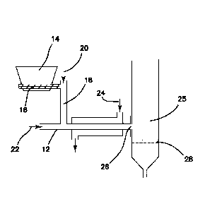
Figure 1 shows a Gas-Jet Biomass Injector with a horizontal biomass feed tube.
Figure 2 shows an embodiment of a Gas-Jet Biomass Injector and reactor.
Figure 3 shows an embodiment of a Gas-Jet Biomass Injector and reactor.
Figure 4 shows a biomass injector assistance system for metering and injecting
pulses of
biomass into a reactor.
DETAILED DESCRIPTION OF THE INVENTION
Figure 1 shows a system with horizontal biomass feed tube 12. During
operation,
biomass in hopper 14 is transported by optional screw feeder 16 into gas
injector tube 18,
through which a gas 20 assists transport of the biomass into horizontal
biomass feed tube 12
which is assisted by gas flow 22. The gas compositions 20, 22 can be the same
or different, and
in some preferred embodiments comprises recycled CO and/or CO2. A coolant
fluid 24 (such as
cool water) can be used to cool the biomass to prevent reaction within the
feeder tube 12.
Biomass enters the fluidized bed reactor in a gas jet through feed port 26 at
a point above
.. distributor 28. In this illustration, the biomass feed tube is horizontal
as it connects to the reactor
and the injection gas flows into the biomass feed tube at a 90 angle. In
preferred embodiments,
to prevent heating of the biomass through a screw, there is no screw feeder
within biomass feed
tube 12 that is in proximity to feed port 26. Horizontal refers to horizontal
with respect to gravity
(that is, perpendicular to the force of gravity).
Figure 2 illustrates the angle a (alpha) which is the angle from horizontal at
which flow 29
through a feed tube travels immediately before passing through a feed port 26
into the fluidized
19
CA 02898743 2015-07-20
WO 2014/116724 PCT/US2014/012579
bed reactor 25. In the embodiment of Fig. 2, there is only one injector gas
flow 30. Note that the
angle of the injector flow gas in upstream portions can be at a different
angle than the gas jet at
the inlet to the fluidized bed reactor.
Fig. 3 illustrates an embodiment in which the fluidized bed reactor contains
sieve trays 34
within the fluidized bed 36. Product stream 39 leaves through the top of the
reactor where any
suspended solids can be removed in a cyclone (not shown) and the nonsolid
components within
the product stream can be separated. Unless specified otherwise, references
within this patent
specification refers to the fluid product stream after solids removal and
prior to separation of the
nonsolid components.
Figure 4 illustrates a biomass injector airlock system constructed of
pneumatic
elastomeric pinch valves 42, 44 to maintain a large pressure difference
between the solids hopper
and reactor 25. Biomass feed is charged to feed hopper, 14, and transferred
via a screw auger or
other mechanical conveying device through open valve 42 into the airlock
chamber, which is
then sealed off by closing valve 42 and brought to a pressure above the
reactor pressure.
Pneumatic pinch valves 42 and 44 are opened or closed by admitting or
releasing gas pressure
through pressure- or electronically-activated valves 43 and 45 into the
pneumatic sleeves of
valves 42 and 44, respectively. The biomass feed can be metered by controlling
the time during
which valve 42 is kept in the open position. A gas reservoir is connected to
the system via an
inlet line 47 and pressure regulator 48 with a tap line on the reactor inlet
used to charge the
airlock chamber prior to releasing pulses of solids by opening valve 44 and
injecting feed into
the feed tube for injection into the reactor, 25, along with an optional
carrier gas 46. An option
shown in Fig 4 is for the carrier gas 46 to supply the injection gas as well
as the carrier gas.
A range of flow rates is possible that will be determined by the size, shape,
density, and
composition of the biomass particles, the size and shape of the reactor, the
composition and
pressure of the gas used as the injector gas, the amount and composition of
the catalyst particles
in the reactor, the desired mixing within the reactor, the desired feed rates
of the biomass and
catalyst, the presence of internal structures within the reactor, and other
factors.
The gas injector conduits and ports that are used to introduce biomass into
the reactor can
be of various sizes depending on the size, shape and composition of the
biomass particles, the
size and shape of the reactor, the composition and pressure of the gas used as
the injector gas, the
amount and composition of the catalyst particles in the reactor, the desired
mixing within the
CA 02898743 2015-07-20
WO 2014/116724 PCT/US2014/012579
reactor. and other factors. The gas jet injector ports may be directed towards
the center of the
reactor, i.e.. radial, or they may be at offset angles, e.g., tangential, in
order to establish more
desirable mixing patterns within the reactor. The gas jet injector ports may
be aimed at any
selected angle, such as horizontally (i.e., 0 with respect to gravity), or
may be angled with
respect to the horizontal such that the biomass flows upwards into the
reactor, or at a downward
angle into the reactor. In some embodiments the angle of the feed port is at
least 15 degrees, at
least 25 degrees, at least 35 degrees, at least 45 degrees, at least 50
degrees, or at least 62 degrees
from the horizontal at the point at which it enters the reactor. Smooth,
aerodynamically designed
feed tubes are preferable to minimize clogging and minimize the fluid flow
needed to move the
biomass; rounded tubes are preferable and a minimum of sharp edges or corners
is desired. A
biomass hopper is situated above an inlet port so that gravity assists the
movement of the
biomass in the downward direction and inhibits clogging or sticking.
The Gas Jet feed system can be used to feed biomass feed into a reactor
continuously, or,
preferably, in short bursts or pulses. The timing of the short pulses of
biomass feed can range
from once every 0.2 seconds to one pulse every 60 seconds or longer, depending
on the size and
geometry of the reactor, biomass characteristics, and gas flow desired. The
duration of flow
during an individual pulse can range from 0.05 seconds to 30 seconds,
depending on the size and
geometry of the reactor, biomass characteristics, gas composition, and gas
flow desired. An
individual pulse can be of much shorter duration than the time between pulses
or can be almost
as long as the time between pulses. It is envisioned that when multiple gas
jet feed ports are
utilized the timing of the pulses could be synchronized to be simultaneous
from multiple ports, or
could be staggered with offsets in time, i.e., delay of the pulse from any one
port with respect to
the pules(s) from another particular port or ports. The optimization of pulse
duration, timing, and
synchronization can easily be conducted experimentally. Pulsed feed is
expected to provide
better mixing due to the more rapid linear velocity that can be achieved with
the same total
volume of gas when it is delivered in pulses.
The Gas Jet feed concept is expected to be advantageous for scaled up reactors
as well,
where keeping the biomass feed cool in auger type feed devices may be
difficult. In a larger
reactor there would likely be numerous injector ports arrayed around the
walls, possibly at
different heights and with different angles of injection. The rate of
injection, i.e., the linear
velocity of the gas and biomass, at different points could cover a wide range
as well, since it
21
CA 02898743 2015-07-20
WO 2014/116724 PCT/US2014/012579
would be useful to have some jets that inject the biomass far into the
interior of the bed while
some jets inject biomass to a lesser distance into the bed to get uniform
mixing across the
reactor. The injectors can terminate at the wall of the reactor or can extend
inside of the reactor
in some cases. Different injectors on the same reactor can extend inside the
reactor to different
.. depths depending on the distribution of biomass desired.
Internal mixing devices and heat exchange devices may be placed within the
reactor. For
example, a number of sieve trays, i.e., plates with numerous small holes that
are set in horizontal
positions, can be located at different heights within the fluid bed. These are
an optional feature
that may be useful to improve mixing and break up large bubbles, particularly
in small reactors.
A single layer of trays may be useful for larger reactors, or multiple layers
may be preferred.
Layers of sieve trays can inhibit the downward movement of the catalyst which
may be
advantageous to establish a 'flow' of catalyst from the top of the bed to the
lower portion of the
bed. In this manner, when catalyst is introduced at the top of the bed, the
most active catalyst
interacts with the most dilute mixture of pyrolysis product vapors, increasing
the chances for
.. reaction and the partially deactivated catalyst lower in the bed interacts
with the more
concentrated mixture of pyrolysis vapors. Sieve trays can establish a partial
'counter-current'
flow of biomass in the upwards direction and catalyst in the downwards
direction, maximizing
catalytic conversion efficiency. In cases where the catalyst is introduced
into the fluid bed at a
lower portion through a dip leg or injector port, the sieve trays can insure
that the freshly
introduced catalyst interacts with freshly introduced biomass, thus setting up
a co-current flow of
biomass and catalyst through the bed. In that case the deactivated catalyst
may be removed from
the upper portion of the bed. Internal structures for fluidized beds are well
known in the art as
described in "Handbook of Fluidization and Fluid-Particle Systems" W-C Yang,
ed., CRC Press,
2003, pages 171-199.
In some embodiments catalyst is mixed with the biomass for injection into the
reactor. The
catalyst can be any temperature, but preferably any catalyst mixed with
biomass is at a
temperature below the temperature of onset of pyrolysis of the biomass such
that when it is
mixed with the biomass the resulting pyrolysis is minimal. Additional catalyst
can be introduced
separately from the biomass and this portion of catalyst could be introduced
at much different
temperature, preferably a high temperature so as to supply heat needed for
pyrolysis to the
reactor. The relative amounts of catalyst introduced with the biomass or
separately can vary over
22
CA 02898743 2015-07-20
WO 2014/116724 PCT/US2014/012579
a wide range. As the catalyst introduced separately typically supplies heat
for the system,
typically a larger mass of catalyst is introduced to supply heat than is
introduced with the
biomass and, in some preferred embodiments, no catalyst is mixed with the
biomass. The
temperature of the reactor can be controlled. for example, by the amount of
catalyst introduced
separately, or its temperature, or the ratio of catalyst introduced by the two
different feed
streams.
The gas used for injection of the biomass can be any gas that is not
detrimental to the
process. Preferably the gas is a recycle gas from the process comprising CO,
or CO), or both CO
and CO2. Preferably the gas could also contain other products such as olefins,
hydrogen, or
methane. Introduction of the olefin-containing recycle gas through the gas
injector is expected to
be preferable to introducing olefins through a distributor plate since the gas
will be kept
relatively cooler in the injector, thus minimizing olefin polymerization and
coking that has been
observed when olefins are introduced through the distributor. The gas jet
stream could also
contain steam, light hydrocarbons such as methane, ethane, propane, etc., and
smaller amounts of
other compounds. Inerts such as nitrogen or argon may also be included, but
their content is
preferably kept low to prohibit their buildup to high concentrations in a
recycle system.
The gas flow rate of the gas jet fluid must allow the linear velocity of the
gas in the gas jet
to be high enough to rapidly transport the biomass into the fluid bed in order
to prevent
premature heating, plugging of the injector tube, and promote good mixing. The
flow of fluid in
the injector includes the carrier fluid that flows continuously through the
injector inlet to
minimize back-flow and the carrier flow that is introduced with the biomass
when using a
biomass metering system such as a biomass injector airlock system or other
system. In some
embodiments the linear velocity of the carrier fluid in the biomass injector
port is at least 25
cm/sec. 50 cm/sec, 100 cm/sec, 150 cm/sec, or at least 200 cm/sec, or at least
225 cm/sec, or at
least 250 cm/sec, or at least 300 cm/sec or from 25 cm/sec to 10,000 cm/sec,
or from 50 to 7,000
cm/sec, or from 100 to 5,000 cm/sec, or from 200 to 5,000 cm/sec, or from 225
to 5,000 cm/sec.
The required linear velocity of the gas in the gas jet in order to prevent
clogging of the
feed tube and inject the biomass particles into the bed will depend on the
size, shape, density,
and other characteristics of the biomass particles. Smaller particles, or more
spherical particles,
or more dense particles flow more easily and require lower flow velocity to
prevent clogging.
Particles with a bulk density of at least 0.10 g/cc can more easily be
transported, preferably at
23
CA 02898743 2015-07-20
WO 2014/116724 PCT/US2014/012579
least 0.25 g/cc, most preferably at least 0.5 g/cc. The bulk density is
measured by filling a tared
measured volumetric container with material, loosely packed and settled only
by mild agitation,
and weighing it to determine the mass of material that fills the volume; the
density is simply the
mass divided by the volume. Particles can have average diameters from 1 micron
to 20,000
microns, preferably 50 microns to 5,000 microns, most preferably 250 microns
to 2,000 microns.
Particles that are not smooth or that have higher moisture contents tend to
flow less easily and
clog more readily and may require higher gas velocities for injection into the
reactor.
Pretreatment of the biomass by drying, grinding, chopping, etc can be used to
modify the particle
characteristics. In general procedures that make the particles flow more
readily such as grinding
to very small particle size (<250 microns diameter) and drying to very low
moisture levels add
processing steps and costs to the overall process.
The balance between the flow rates and volumes introduced through the Gas Jet
Feed
Ports and the Fluidization Feed Port could vary over a wide range. In some
embodiments, the
ratio of gas flow rate injected with the biomass to the gas flow rate
introduced through the
fluidization port is less than 0.1, less than 0.25, less than 0.5, less than
1, less than 2, less than 3,
less than 5, or less than 10, or between 0.001 and 10, or between 0.01 and 5,
or between 0.1 and
2. The preferred levels of ratio of the flow rate at the injection port (also
known as feed port) to
flow rate through the fluidization port applies to the case where there is a
single feed port and a
single fluidization port; and it also applies in the case of multiple ports,
in which the summed
.. flows of the feed port(s) are divided by the sum of flow through the
fluidization port(s).
Alternatively, much lower rates of fluidization flow may be possible with the
use of gas jet
injection ports, or it may be eliminated altogether. Some fluidization flow
through the distributor
or otherwise introduced into the lower portion of the reactor is preferred to
keep the more dense
solids from collecting on the bottom of the reactor. In some embodiments the
distributor plate is
absent and the fluidization fluid is introduced via a distribution system or
sparger located within
the lower portion of the fluid bed. Gas distributors and plenum designs for
fluidized beds are
well known in the art as described in "Handbook of Fluidization and Fluid-
Particle Systems" W-
C Yang, ed., CRC Press, 2003, pages 155-170.
The balance between the gas flow temperatures and volumes introduced through
the Gas
Jet Feed Ports and the Fluidization Feed Port are also an important factor in
improving
production of useful products such as aromatics, olefins, heavy hydrocarbons,
or some
24
combination of these. A normalized feed temperature can be defined that is a
weighted average
of the temperatures of the gas feed streams and can be calculated as [(flow
rate of injected feed
gas * temperature of injected feed gas) + (fluidization gas flow rate *
fluidization gas
temperature)] / (injected gas flow rate + fluidization gas flow rate). This
definition assumes rapid
mixing of the injected and fluidization gases, typically in the volume that is
immediately above
the distributor. It is believed that normalized feed temperatures below the
preferred range will
result in greater char and lesser aromatics, while normalized feed
temperatures above the
preferred range will result in more CO and coke. Normalized feed temperatures
can range from
50 to 700 C, or 75 to 650 C or preferably from 100 to 600 C depending on
the biomass feed
.. composition, gas feed composition, catalyst, pressure, and other process
parameters.
The reactor can be operated in either batch mode wherein the catalyst is
charged before
the reaction is started, or in continuous mode, wherein catalyst is added and
removed
continuously. During continuous operation both catalyst and biomass are fed to
the reactor. The
mass ratio of the catalyst:biomass feeds can, in some preferred embodiments,
range from 0.3 to
20, or from 1 to 10, or from 2 to 6, or from 2.5 to 4. In some preferred
embodiments, the ratio is
10 or more; for example, in the range of 10 to 40 or 10 to 20.
The space velocity of the CFP process, defined as the rate of biomass feed
divided by the
mass of catalyst in the reactor, typically expressed in inverse time units,
can range from 0.05 hr-1
to 20 hr-1, or from 0.1 hr-1 to 10 hr-1, or from 0.2 hr-1 to 5 hr-1, or from
0.3 hr-1 to 2 hr-1. In some
embodiments the space velocity is at least 0.1, at least 0.2, at least 0.3, at
least 0.4, at least 0.5, at
least 0.8, or at least 1.0 hr-'.The conditions of the CFP process can be any
of those summarized
in US 8277643.
Catalyst components useful in the context of this invention can be selected
from any
catalyst known in the art, or as would be understood by those skilled in the
art made aware of
this invention. Functionally, catalysts may be limited only by the capability
of any such material
to promote and/or effect dehydration, dehydrogenation, isomerization, hydrogen
transfer,
aromatization, decarbonylation, decarboxylation, aldol condensation and/or any
other reaction or
process associated with or related to the pyrolysis of a hydrocarbonaceous
material. Catalyst
components can be considered acidic, neutral or basic, as would be understood
by those skilled
in the art. Alternatively, alone or in conjunction with such and other
considerations, catalysts can
be selected according to pore size (e.g., mesoporous and pore sizes typically
associated with
Date Recue/Date Received 2020-04-09
CA 02898743 2015-07-20
WO 2014/116724 PCT/US2014/012579
zeolites), e.g., average pore sizes of less than about 100 Angstroms, less
than about 50
Angstroms, less than about 20 Angstroms, less than about 10 Angstroms, less
than about 5
Angstroms, or smaller, although pores smaller than the kinetic diameter of
aromatic rings are
significantly less desirable. In some embodiments, catalysts with average pore
sizes of from
about 5 Angstroms to about 100 Angstroms may be used. In some embodiments,
catalysts with
average pore sizes of between about 5.5 Angstroms and about 6.5 Angstroms, or
between about
5.9 Angstroms and about 6.3 Angstroms may be used. In some cases, catalysts
with average pore
sizes of between about 7 Angstroms and about 8 Angstroms, or between about 7.2
Angstroms
and about 7.8 Angstroms may be used. Catalysts may have bimodal or multimodal
distributions
of pores such that there are significant numbers of pores of a small size and
a significant number
of pores of a larger size or sizes. Preferred catalysts include natural or
synthetic ferrierite, zeolite
Y, zeolite beta, mordenite, MCM-22, ZSM-5, ZSM-12, ZSM-23, ZSM-35, ZSM-57. SUZ-
4, EU-
1, ZSM-11, (S)A1P0-31, SSZ-23. A particularly preferred catalyst is ZSM-5, or
one that
comprises ZSM-5. In some embodiments, the catalyst may comprise a metal and/or
a metal
oxide. Suitable metals and/or oxides include, for example, nickel, platinum,
vanadium,
palladium, chromium, manganese, iron, cobalt, zinc, copper, chromium, gallium,
any of the rare
earth metals, ie elements 57-71 of the Periodic Table, or any of their oxides
or any combinations
of these.
EXAMPLES
Comparative Example 1.
Catalytic fast pyrolysis (CFP) of pinewood was conducted in a fluidized bed
reactor. The
fluidized bed reactor was 2 inches outer diameter (OD) and 24 inches in height
and was made of
316 stainless steel. Inside the reactor, the catalyst bed was supported by a
distributor plate made
of 316 stainless steel plate with 1/16 inch circular openings. The reactor,
shown schematically in
Figure 1, was fitted with a screw auger of 0.625 inch OD, 0.39 inch inner
diameter (ID)
positioned horizontally, through which the biomass was fed by rotation of the
auger.
The reactor was loaded with 102 g of 2%Ga/ZSM5 catalyst prior to the
experiment and
the catalyst was calcined in-situ in air at the flow rate of 3.0 SLPM for 2
hours at 580 C. The
pine saw dust (PSD) was ground and sieved to 0.25-2 mm particle size. About
300 grams of pine
26
CA 02898743 2015-07-20
WO 2014/116724 PCT/US2014/012579
saw dust was weighed and loaded into the hopper system. The reactor was purged
with a flow of
N2 at 3.0 SLPM for 30 minutes prior to starting the experiment.
The reactor was heated to 580 C and the fluidization gas feeding tube was
heated to
approximately 500 C. Biomass flow rate was accurately controlled by an augur
inside the
hopper that delivers the biomass to the feed tube. The solid biomass
(pinewood) was introduced
into the reactor from a side feeding tube with N2 flow. Gas flow rate through
the biomass screw
auger feed tube was 0.5 SLPM giving a calculated linear velocity at 25 C of
11.8 cm/second at
the entry to the reactor. The biomass feed rate was adjusted to about 1.0
g/min. The feeding tube
enters the reactor approximately 1 inch above the distributor plate. During
reaction, 1.0 SLPM of
N, was passed into the reactor through the distributor plate to fluidize the
catalyst in addition to
the feeding tube N2 flow.
The reactor effluent exited the reactor from the top through a heated cyclone
(350 C) to
remove solid particles, including small catalyst and char. The effluent
exiting the cyclone flowed
into a product collection system that included two bubblers and three
condensers. The bubblers
were placed in an ice water bath and charged with 150 ml of isopropanol inside
as solvent; the
three condensers contained no solvent and were placed inside a Dry
Ice/isopropanol bath. The
uncondensed gas phase products that exited the last condenser were collected
in gas bags. The
reaction time was typically 30 min and two gas bag samples were taken at 15
and 30 minutes
time on stream after initiating the feed of biomass. After each bag was taken,
the total gas flow
.. rate was measured with a bubble flow meter; at least 4 measurements were
made and the average
was used for performance calculations. The gas bags samples were analyzed by
injection into a
Shimadzu GC 2010 that had been calibrated with analytical standard gas
mixtures.
The contents of each of the two bubblers were collected. The contents of the
three
condensers were weighed and combined into a single sample. The condensers were
rinsed with
isopropanol to produce a fourth sample. All 4 liquid volumes were measured and
weights
determined. Liquid samples were all analyzed by injection into a Shimadzu GC
2014.
The carbon yield of aromatics and olefins was determined to be 2.01%.
Comparative Example 2.
The experiment was repeated with a biomass feed auger flow rate of 1.0 SLPM,
which
provides a linear velocity of 24 cm/second in the horizontal biomass feed tube
at the entry to the
27
CA 02898743 2015-07-20
WO 2014/116724 PCT/US2014/012579
reactor. A fresh sample of 100 g of catalyst was charged to the reactor. The
biomass feed rate
was adjusted to 0.78 g/min.
The carbon yield of aromatics and olefins was determined to be 9.55%.
Poor mixing, premature heating of the biomass, and inadequate transport of the
biomass
into the catalytic fluid bed were observed as evidenced by the large amount of
char formed and
the low yields of aromatics and olefins. The auger and tube became hot and the
metal became
discolored.
Gas Jet Experiments
The screw auger was removed from the auger feed system, leaving the empty
auger tube
in place to serve as the conduit for biomass feed to the reactor. An
experiment was attempted
with biomass fed through the auger tube (no screw) with 2 SLPM gas flow
through the auger
tube and 1 SLPM fluidization gas fed through the distributor. The empty auger
tube entered the
reactor horizontally. Other conditions were as in Comparative Experiment 1.
Biomass
accumulated in the auger tube and eventually clogged the transfer line from
the biomass hopper
outlet to the auger tube due to the low gas velocity and horizontal position
of the feed tube. The
feed of biomass stopped and the reactor was shut down.
A cold flow fluid bed reactor was assembled that included a clear
polycarbonate tube to
permit observation of the fluidization within the reactor. The horizontal tube
shown in Figure 1
was not effective at transporting the biomass into the reactor in cold flow
tests. Much of the
biomass was observed to sit in the horizontal transfer tube.
It was determined experimentally in the cold flow device, that with a 0.25
inch OD (ID =
0.2 inch) gas-jet injection tube and an entry angle of about 26 degrees from
the horizontal the
flow rate of the carrier gas needed to be at least about 2.5 SLPM to prevent
clogging with
biomass particles ¨ 2 mm in size, with a biomass feed rate of 0.5-1.0
g/minute. Lower carrier gas
flow rates clogged the tube. The linear velocity of the injector gas was
calculated to be ¨ 224
cm/second at 25 C in the injector tube.
Examples 3 through 12
The biomass transfer tube was replaced by a curved 0.25-inch OD SS-316 tube
extending
from the feed hopper to the biomass inlet port. The feed hopper was situated
above and to the
side of the reactor. The angle of entry of the feed tube into the fluid bed
was 26 degrees from the
28
CA 02898743 2015-07-20
WO 2014/116724 PCT/US2014/012579
horizontal, as shown in Figure 2. A series of sieve trays made of perforated
316 stainless steel
with one-eighth (0.125) inch openings and 42% open area were installed inside
the reactor, as
shown in Figure 3. There were six sieve trays attached to a central, threaded
rod and there was a
1-inch spacing between the sieve trays.
A series of experiments was conducted with the conditions as summarized in
Table 1.
As shown in Table 1 (for example, compare examples 9 and 10 with 11 and 12),
the ratio
of injection flow rate (which is measured at the interface between the
injection tube and the
reactor, in other words, at the solids inlet to the reactor) to fluidization
flow rate (measured at the
fluidization gas inlet to the fluidized bed) was surprisingly found to show
better results (higher
.. aromatics, higher aromatics and olefins, and higher benzene and toluene) at
a ratio of about O.]
or more, and in some embodiments this ratio is selected to be in the range of
0.05 to 5; in some
embodiments 0.1 to 5; and in some embodiments 0.1 to 2.
The Nominal Linear Velocity of the feed gas at the entry to the reactor was
calculated by
dividing the volumetric flow of gas in the gas jet at standard conditions (25
C, 1 atm) by the
cross sectional area of the inlet port.
It was also surprisingly discovered that, regardless of (that is, independent
of) the
temperature in the reactor bed, a relatively high temperature of the
fluidization gas at the inlet to
the fluidized bed reactor resulted in significantly superior results.
Preferably, the temperature of
the fluidization gas at the inlet to the fluidized bed is about 500 C or
more, preferably about 550
C or more, in some embodiments at least 575 C. The upper limit of this
temperature parameter
has not yet been determined but could be determined with routine
experimentation. In some
embodiments, the upper limit (in combination with any of the limits mentioned
above) is 900 C
or less, in some embodiments 800 C or less, in some embodiments 700 C or
less, in some
embodiments 650 C or less. Generally, a high yield of the sum of aromatics
and olefins is
desirable; however, in cases in which very low yields of olefins (that is, a
high ratio of aromatics
to olefins) is desired, then it may be desirable to operate with a temperature
of the fluidization
gas at the inlet to the fluidized bed of about 400 C or less, in some
embodiments in the range of
0 to about 300 C, although the low temperature was also found to be
associated with a relatively
high yield of undesirable polycyclic aromatics.
Another surprising discovery was that superior results can be obtained by
controlling the
normalized feed temperature in a fluidized bed reactor. The superior results
can be obtained
29
CA 02898743 2015-07-20
WO 2014/116724 PCT/US2014/012579
using normalized feed temperatures between 100 and 650 C, preferably between
200 and 600
C, still more preferably between 300 and 560 C. This can be achieved, in
preferred
embodiments, by controlling the temperatures and/or flow rates a mixture of
fluidization gas and
injection gas flow carrying biomass into the region below the distributor in a
fluidized bed
reactor. The Normalized feed temperature is defined as (flow rate of injected
feed gas
temperature of injected feed gas) + (fluidization gas flow rate * fluidization
gas temperature) /
(injected gas flow rate + fluidization gas flow rate). This definition assumes
rapid mixing of the
injected and fluidization gases, typically in the volume that is immediately
above the distributor.
It is believed that normalized feed temperatures below the preferred range
will result in greater
char and lesser aromatics, while normalized feed temperatures above the
preferred range will
result in more CO and coke.
Example 13
The reactor of Example 12 that utilized a gas jet injector feed in a 2-inch
diameter nominal
pipe reactor was charged with 158 g of Catalyst A, a commercially obtained
fluid bed ZSM-5
catalyst containing approximately 40 weiaht% crystalline ZSM-5 in an inert
binder. The feed gas
flow rate, biomass feed rate, and temperatures were adjusted as shown in Table
2. Ground
hardwood pellets containing 46.99% carbon and 6.16% hydrogen were used as the
biomass feed.
The results show that a high yield of aromatics and olefins can be achieved
with an injection
velocity of 69 cm/sec and a normalized feed temperature of 150 C when a gas
jet biomass feed
system is used.
Example 14
The reactor of Example 13 was charged with 161 g of Catalyst A and the
experiment was
repeated. The results demonstrate that the process is highly reproducible
using a gas jet injector
system.
Example 15
A reactor consisting of a 4 inch diameter 316 stainless steel pipe with a free
board height
of 30 inches was constructed. The top of the freeboard expands to 6 inches to
suppress
entrainment of catalyst particles in the exit gas stream. The catalyst bed is
supported by a
distributor made from a 316 stainless steel wire mesh (50 X 250 mesh). The
bottom of the
reactor below the distributor plate serves as a gas preheater zone. The
catalyst is fluidized with
nitrogen controlled by a mass flow controller. The reactor is externally
heated with a four-zone
CA 02898743 2015-07-20
WO 2014/116724 PCT/US2014/012579
electric furnace to minimize the temperature gradient across the reactor. All
zones were
maintained at reaction temperature. The temperatures inside the reactor were
measured by K-
type thermocouples inserted to a penetration depth of 1 cm.
A biomass hopper and biomass injection assistance system as shown in Figure 4
was fitted
to the reactor. The biomass injection assistance system consists of two pinch
valves and an
intermediate chamber that allows for isolating the biomass hopper from the
reactor pressure.
With the auger in the biomass hopper running, biomass falls through the top
pinch valve (open),
into the intermediate chamber, above the bottom pinch valve (closed). The top
valve closes, the
chamber is pressurized to just above the reactor pressure, the bottom valve
opens, and biomass is
injected into the reactor with assistance of carrier nitrogen.
The reactor was charged with 538 g of catalyst B, a commercially obtained
fluid bed
catalyst containing approximately 50 wt% ZSM-5. The hopper was charged with
200 g of
ground hardwood pellets and the reactor was brought to reaction temperature
with a flow of N2.
The biomass feed system was started with biomass pulses spaced approximately
2.1 seconds
apart so that each pulse delivered approximately 0.2 g of biomass.
The results of Example 15 show that high yields of aromatics and olefins can
be obtained
with a pulsed biomass injector system.
Example 16
A pilot unit was constructed that included a reactor with internal diameter of
11.38 inches
and height of 18 inches. The distributor consists of a wire mesh distributor
plate. A feed hopper
with a metering auger for delivering biomass and a biomass injection
assistance system to pulse
the biomass into the reactor were fitted to the reactor. The feed tube where
the biomass entered
the reactor made a 60 degree angle with the horizontal.
The reactor was charged with 4103 g of Catalyst A and the system was heated to
reaction
temperature. The biomass hopper was charged with about3 kg of ground hardwood
pellets
(49.9% C, 5.9% H) and the experiment was started. Biomass was fed for 30
minutes at a rate of
43.2 g/min, and then the reactor was flushed an additional 10 minutes with
nitrogen to collect
materials remaining in the reactor. The outlet of the reactor was passed
through a knock-out pot
maintained at about OC, and two isopropanol bubblers maintained at 00 C, and a
condenser
maintained at -78 C. The contents of the collection vessels were combined for
the liquid product
analysis. A sample of the gases that exited the condenser was injected into a
gas GC for analysis.
31
CA 02898743 2015-07-20
WO 2014/116724 PCT/US2014/012579
A sample of the used catalyst and char was removed, dried at 120 C, separated
into fine
(catalyst) and larger (char) particles, and analyzed for carbon content by
calcining in air at 600 C.
The results of Example 16 summarized in Table 2 demonstrate that the pulsed
feed of
biomass provides a high yield of aromatics and olefins in large reactors with
larger diameters.
The results demonstrate that the CFP process can be operated with a very low
biomass feed gas
flow to fluidization gas flow ratio (0.05).
Example 17
The procedures of Example 16 were repeated with a fresh charge of 4197 g of
Catalyst A.
The results summarized in Table 2 demonstrate that the process is reproducible
with the very low
ratio of biomass feed gas flow to fluidization gas flow.
Example 18
The procedures of Example 16 were repeated with a fresh charge of 5200 g of
catalyst A
but with lower biomass flow rate and higher ratio of biomass feed gas flow to
fluidization gas
flow. Under these conditions the yields of aromatics and olefins were less
than in Examples 16
and 17, but remained far above what had been obtained with an auger feed
system that was
directly connected to the reactor as in Examples 1 and 2.
Surprisingly, we discovered that the gas-injected reaction with a relatively
lower biomass
feed rate resulted in lower aromatic yield (compare Examples 17 and 18). Thus
showing that the
use of gas injection results in better yield and a more efficient use of
catalyst.
Example 19
The procedure of Example 18 was repeated with 5162 g of Catalyst B in place of
Catalyst
A. The results of Example 19 show that different catalysts can be used in the
CFP process with
gas jet injection to achieve high yields of aromatics and olefins. The results
of Example 19
demonstrate that the choice of catalyst and operating conditions to get high
yields are not the
same for all catalysts, ie the conditions must be matched to the catalyst.
Example 20
In this example the apparatus of Example 16 was additionally fitted with a
catalyst hopper
for continuous addition of catalyst to the process during operation. The
catalyst feed system
consists of a 1/8" thick 316SS pressurized vessel providing catalyst by
gravity via a rotary ball
valve positioned above the reactor of working capacity 28.3 liters fitted with
internal electric
32
CA 02898743 2015-07-20
WO 2014/116724 PCT/US2014/012579
cable-style heater for pre-heating catalyst during continuous operation and a
nitrogen
pressurization line to maintain inert headspace and provide assist pressure to
continuous catalyst
feed. The catalyst hopper could be refilled during the experiment as needed.
The catalyst hopper was charged with about 40 kg of catalyst B and the reactor
was
charged with 4800 g of catalyst B. The biomass hopper was charged with 3 kg of
ground
hardwood chips. The reactor was heated to reaction temperature under nitrogen
and the feeds
were initiated as shown in Table 2. Catalyst feed rate was 95 g/minute,
biomass feed rate was
30.9 g/minute, and the ratio was 3.1. The experiment was continued for 4
hours; the results of the
first hour of operation are collected in Table 2.
The results of Example 20 show that a high yield of aromatics and olefins can
be obtained
in a large reactor under conditions of continuous catalyst and biomass feed
using pulsed jet
injection to feed the biomass.
Example 21
The experiment of Example 20 was repeated with a fresh charge of Catalyst B.
The feed
rate of catalyst B was increased relative to Example 20 to give a
catalyst/biomass feed rate of
3.9.
Results summarized in Table 2 show that by adjusting the catalyst/biomass feed
ratio the
yield of aromatics can be improved using a pulsed gas jet injector to feed the
biomass. The
results show that the pulsed gas jet injector can be used to successfully
scale up the CFP process
with aromatics yields as high as those observed in much smaller (2-inch OD)
reactors (Examples
13-14).
Comparing the results of Examples 14, 15 and 19-22 to Examples 16, 17, and 18
shows
that the yield of aromatics is generally higher at the higher injection
velocities used in Examples
14, 15, and 19-22 than with the lower injection velocities used in Examples 16-
18.
33
CA 02898743 2015-07-20
WO 2014/116724
PCT/US2014/012579
Table 1. Catalytic Fast Pyrolysis results in 2-inch (5 cm) OD Fluid Bed
Reactor.
Experiment Number 1 2 3 4 5 _ 6 7 8 9 10 11
12
Gas- Gas- Gas- Gas- Gas-
Auger Auger Gas-Jet Gas-Jet Gas-Jet
Gas-Jet Gas-Jet
Jet Jet Jet Jet Jet
Fluidization Flow Rate, SLPM 1.0 1.0 1.5 2.5 2.5 0.5 0.5
0.5 1.5 1.5 3.0 3.0
Biomass Injection Flow, SLPN1 0.5 1.0 2.5 2.5 2.5 2.5
2.5 2.5 3.0 3.0 1.5 1.5
Run Time, min 30 _ 30 60 45 75 29 30 , 45 , 30
32 144 240
Catalyst charged, g 102.0 100.0 149.8 149.8 150.1 150.1
248.5 350.2 150.5 150.0 149.6 150.4
Biomass PSD PSD PSD PSD PSD P50 PSD PSD Newsprin Newsprin
Newsprin Newsprin
t t t
t
Biomass Flow Rate, g/min 1.03 0.78 0.76 0.71 0.78 0.66
0.62 0.62 0.90 1.26 0.75 0.77
Fluid Bed Temp, oC 580 580 550 573 558 570 580 580
580 580 583 583
Fluidization Gas Inlet I emp,
355 342 236 585 609 609 577
577 577 577
oC
Normalized Feed Temp, oC 149 184 131 118 122 122 209
209 393 393
26
Feed angle from horizontal Horizon Horizon 26 deg 26 deg 26
deg 26 deg 26 deg deg 26 deg 26 deg 26 deg 26 deg
tal tal
Inlet Tube diameter, ID cm 1.0 1.0 0.5 0.5 0.5 0.5 0.5
0.5 0.5 0.5 0.5 0.5
Linear velocity of gas jet,
11.8 23.6 224 224 224 224 224 224 269
269 135 135
cm/sec
Flow ratio Gas jet/Distributor 0.5 1 1.7 1 1 1 5 5
5 2 2 0.5 0.5
lProduct Yields..ice.r.13..9100 U ..g..M..g.A
.......R....,..,..A....õ........EME....ank...a..õ...MEN.M.M L..... N..an..M
g,.MM.....] .g.M.1........... UM.........A..... ,.....õ .M
Aromatics ow. 8.8% 21.3% 18.1% 19.4% 83% 14.2% 16.0 21.1% 22.4% 18.6%
18.5%
%
Olefins 1.1% 0.7% 1.9% 2.1% 2.0% 6.8% 10.6%
10.9 6.2% 7.8% 5.6% 6.1%
%
Aromatics 26.9 + Olefins 2.0% 9.6% 23.2% 20.3% 21.4%
15.2% 24.8% 27.3% 30.2% 24.2% 24.6%
%
CO 13.5% 6.5% 14.6% 14.9% 13.9% 14.3% 22.1% 27.6 19.9% 17.5%
15.0% 17.1%
%
Methane 9.2% 6.9% 2.4% 2.5% 1.1% 3.2% 4.3%
3.8% 2.7% 2.4% 1.7% 2.1%
CO2 3.2% 3.3% 4.2% 3.9% 3.9% 4.4% 6.5%
8.1% 6.7% 5.8% 4.6% 6.0%
Coke 11.7% na 9.8% 3.9% 12.9%
14.0 na na na na
%
Char 5.8% na 11.4% 6.8% 3.1% 6.1%
na na na na
Total Identified Products 27.9% 26.2% 62.0% 41.5% 61.5%
47.8% 73.8% 86. 56.6% 55.9% 45.4% 49.7%
%
PSD = Pine Sayidust
5
34
CA 02898743 2015-07-20
WO 2014/116724 PCT/US2014/012579
Table 2. Fluid Bed CFP experiments
Experiment 13 14 _ 15 16 17 18 _ 19 20 21 22
Continu Continu Continu
Catalyst Feed Type Batch Batch Batch Batch Batch Batch
Batch
ous ous ous
Reactor diameter, OD,
2 2 4 12 12 12 12 12 12 12
inches ..
Duration, hours 0.5 0.5 0.5 0.5 0.5 0.5 _ 0.5 1
1 1
Catalyst A A B A A A B B B B
Catalyst charged, g 158 161 538 4103 4197 5200 5162
4800 4800 4700
Biomass Feedrate,
1.81 1.88 5.50 43.3 43.2 34.3 34.4
30.9 31.6 31.4
g/min
Biomass Feed Continuous Continuous Pulsed Pulsed Pulsed
Pulsed Pulsed Pulsed Pulsed Pulsed
Catalyst feedrate, g/min - - - - - - - 95 123
126
Catalyst to Biomass
- - - - - - - 3.1 3.9 4.0
feed ratio
WHSV, hr-1 0.90 0.90 0.66 0.63 0.62 0.40 0.40
0.39 0.40 0.39
Reactor Temperature, C , 575 _ 575 , 575 575 575 575
575 , 558 ... 544 , 558
Fluidization gas, SLPM 1.5 1.5 2.3 110 110 68 68 68
68 68
Fluidization gas Temp,
400 400 400 560 560 560 560 543
529 543
oC, (est.)
Feed carrier gas, SLPM 3.0 3.0 3.2 5.0 5.0 5.0 8.0
8.0 8.0 8.0
Feed/Fluidization Gas
2.0 2.0 1.4 0.05 0.05 0.07 0.12 0.12
0.12 0.12
flow ratio
Normalized feed Temp,
150 150 182 537 537 504 504 488
476 488
oC
Inlet tube diameter, ID,
0.5 0.5 1.0 1.9 1.9 1.9 1.9 1.9
1.9 1.9
cm
Injection velocity,
278 278 82 31 31 31 SO SO 50
SO
cm/sec
Carbon Yields, %
Aromatics 20.5 20.3 19.6 18.2 16.2 11.5 18.5
17.1 20.7 20.1
Olefins 9.5 9.8 6.9 5.6 5.3 7.6 8.1 4.8
4.9 5.7
CO 18.9 19.3 19.3 18.1 22.2 23.2 24.9
16.0 15.9 17.9
Methane 3.4 4.6 3.1 2.4 3.1 3.2 3.0 1.4
1.6 1.7
CO2 4.5 4.7 4.0 4.6 5.5 5.3 6.2 4.3
4.1 4.5
Parafins, alkynes, furans 0.8 1.2 0.0 0.6 0.7 1.0 0.7
0.5 0.5 0.6
unknowns 2.4 3.0 3.7 10.2 9.8 2.4 5.6 7.7
7.4 6.8
Coke & Char 30.0 , 25.2 , 31.1 36.0 40.7
38.3 , 34.9 43.6 , 41.9 , 36.8
Total 90.0 88.2 87.6 95.6 103.5 92.4 101.6
95.4 96.8 94.1
CA 02898743 2015-07-20
WO 2014/116724 PCT/US2014/012579
Conclusions
The geometry of the injector port, linear velocity of the injector gas, and/or
the conditions
of the gas jet can be important factors in achieving biomass introduction,
good mixing in the
reactor, and high yields of aromatics and olefins.
In any of the claims or other descriptions, it should be recognized that the
invention
includes apparatus, methods and systems. A system includes both apparatus and
conditions
within the apparatus, for example fluid flows and temperatures. In any of the
claims, the term
"apparatus" can be replaced by the term "system."
36