Note: Descriptions are shown in the official language in which they were submitted.
CA 02898903 2015-07-29
17242.9 1
METHOD FOR MEASURING THE DISTANCE BETWEEN A WORKPIECE AND
A MACHINING HEAD OF A LASER MACHINING APPARATUS
----------------------------------------------------- -------
BACKGROUND OF THE INVENTION
1. Field of the invention
The invention relates to a method for measuring the
distance between a workpiece and a machining head of a
laser machining apparatus by means of which workpieces
can be welded, cut or otherwise machined.
2. Description of the prior art
Laser machining apparatus usually comprise a laser
radiation source, which may be, for example, a CO2 laser,
a fibre laser or a disc laser. A laser machining
apparatus additionally includes a machining head, which
focuses the laser radiation, generated by the laser
radiation source, in a focal spot, and a beam delivery
means, which delivers the laser radiation, generated by
the laser radiation source, to the machining head. The
beam delivery means in this case may comprise optical
fibres or other optical waveguides, and/or one or more
deflecting mirrors having planar or curved faces. The
machining head may be attached to a movable robot arm or
to another positioning device that enables three-
dimensional positioning. The laser radiation source in
CA 02898903 2015-07-29
17242.9 2
this case is frequently disposed at a greater distance
from the machining head or from a positioning device
carrying the machining head.
Usually, the workpieces to be machined are positioned in
relation to the machining head by means of handling
devices. By means of the robot, the machining head is
then guided over the stationary workpiece, at a distance
of a few millimetres. At the same time, process gas flows
out of the machining head, which process gas, depending
on the machining operation, reacts chemically with the
material or merely performs the function of removing
residues, produced during the machining operation, from
Lhe machining site.
In the use of such laser machining apparatus, it is
difficult to position the focal spot in an exact manner
on the surface of the workpieces to be machined, the
diameter of which focal spot is usually between 100 pm
and 500 pm in the case of welding work, and may be 20 pm
and less in the case of cutting work. It is ideal if the
focal spot is tracked in a process of feedback control of
the actually existing spatial arrangement of the
workpieces. For this purpose, the actual spatial
arrangement of the workpieces to be machined, relative to
the machining head or to another reference point, is
measured in real time during the laser machining
operation.
CA 02898903 2015-07-29
17242.9 3
For the measurement, the machining location, for example,
can be observed by means of a camera, which captures a 2D
projection of the workpieces. However, if the beam path
of the camera is coaxial with the laser radiation, as is
known in the prior art, only a lateral offset, along the
X and Y directions, can be measured with precision, but
not the distance of the workpiece in relation to the
machining head, along the Z direction. A high process
quality requires measuring accuracies in the Z direction
that are in the order of magnitude of about 400 pm for
welding work and in the order of magnitude of about
100 pm for cutting work.
Further known measuring methods are light-section methods
and triangulation methods. Capacitive sensors are also
used, especially for distance measurement, insofar as the
workpieces have a sufficiently high electrical
conductivity.
In addition, the use of optical coherence tomographs,
OCT, was also proposed some time ago, for the purpose of
measuring distance during laser machining, of., in
particular, EP 1 977 850 Bl, DE 10 2010 016 862 B3 and DE
10 2012 207 835 Al. Optical coherence tomography makes it
possible to effect highly precise measurement of
distance, and even to generate a 3D profile of the
scanned surfaces if the measuring beam is guided over the
surfaces in the manner of a scanner. Moreover, unlike
capacitive sensors, coherence tomographs allow the
CA 02898903 2015-07-29
17242.9 4
distances in relation to non-metallic materials, such as
fibre-reinforced plastics, to be measured.
It has been found, however, that the measurement of
distance by means of coherence tomographs, which is
highly promising per se, does not deliver reliable
measurement results under all conditions.
SUMMARY OF THE INVENTION
It is an object of the invention to specify a method for
measuring the distance between a workpiece and a
machining head of a laser machining apparatus, by which
the distances can be measured in a particularly reliable
and precise manner. It is additionally an object of the
invention to specify a machining head that is suitable
for executing the method.
In respect of the method, the object is achieved,
according to the invention, by a method having the
following steps:
a) providing a machining head comprising a housing that
has an interior and an opening for emergence of the
laser radiation from the machining head,
b) directing the laser radiation on to the workpiece,
after the laser radiation has passed through the
interior and the opening;
CA 02898903 2015-07-29
17242.9 5
c) generating an object beam by means of a light source
of an optical coherence tomograph, and directing the
object beam on to the workpiece in such a manner
that the object beam passes through the interior and
the opening before being incident upon the
workpiece;
d) capturing the reflection of the object beam
reflected from the workpiece;
e) superimposition the reflection of the object beam
with a reference beam generated by the light source
of the coherence tomograph;
f) determining the distance between the machining head
and the workpiece from an interference signal
obtained by the superimposition in step e);
wherein, according to the invention, in addition to the
object beam, a measuring beam passes through the
interior, which measuring beam is used to compensate
falsifications of the measured distance that have been
caused by pressure fluctuations in the interior.
The invention is based on the recognition that a cause of
imprecise measurement results may be pressure
fluctuations in an interior through which there passes,
not only the laser radiation, but also the object beam of
the coherence tomograph. Usually, a process gas flows
CA 02898903 2015-07-29
17242.9 6
through this interior, which process gas is directed on
to the machining site via the opening through which the
laser radiation and the object beam also emerge from the
housing of the machining head. Depending on the nature of
the processing and the material being processed, the
process gas in this case may react chemically with the
workpiece, or merely perform the function of mechanically
expelling a melt film, produced by the laser radiation,
or vapours.
As a rule, the flow conditions close to the opening and
the machining site are complex, and may result in
pressure fluctuations, in the order of magnitude of
several bar, occurring in the interior through which the
object beam passes. Since the refractive index is
proportional to the gas pressure, the pressure
fluctuations result in corresponding variations in the
refractive index distribution in the interior. These
variations, in turn, affect the optical path length that
is traversed by the object beam in the interior. Since
the object beam cannot distinguish whether a change in
the optical path length results from a varied distance or
from a varied refractive index in the interior, pressure
fluctuations in the interior result in apparent
variations of distance, and therefore in incorrect
measurements.
Since, according to the invention, a measuring beam, in
addition to the object beam, passes through the interior,
CA 02898903 2015-07-29
17242.9 7
falsifications of the measured distance that have been
caused by the described pressure fluctuations in the
interior can be compensated. Ideally, the measuring beam
passes through the interior close to the object beam, or
even on the same light path. It is thereby ensured that
the pressure distribution to which the object beam is
subjected matches, as far as possible, the pressure
distribution that is captured by the measuring beam.
The highly precise distance values may be used, for
example, to keep the distance between the machining head
and the workpiece to a specified value, by way of a
feedback control. Additionally or alternatively, a
feedback control of the position of the focal spot of the
laser radiation may be effected by means of focussing
optics arranged in the machining head, using the measured
distances.
In the case of one embodiment, the measuring beam is
reflected at a reflective face that is realized on an
inner face of a housing of the machining head that
delimits the interior. The measuring beam thereby passes
twice Through the interior, with the result that a
greater measuring accuracy is achieved. Moreover, in this
way, sensitive optical components required for evaluating
the measuring beam can be arranged at a greater distance
from the end of the machining head that faces towards the
workpiece and that is subjected to high thermal and
mechanical loads.
CA 02898903 2015-07-29
17242.9 8
In particular, it is a possibility for the measuring beam
that is incident upon the reflective face to be reflected
back into itself. in this way, the measuring beam can
enter the interior and, after being reflected at the
reflective face, emerge again from the interior via the
same optics.
It is particularly advantageous if the reflective face is
in immediate proximity to the opening. It is thereby
ensured that even pressure fluctuations in direct
proximity to the opening are taken into account by the
measuring beam.
In the case of one embodiment, the reflective face is
realized on the inner face of an outlet nozzle that
comprises the opening. During the measurement of the
distance, the already mentioned pressurized gas emerges
from the opening, in addition to the laser radiation and
the object beam.
In principle, the measuring beam may be generated by any
optical measuring device by which pressure fluctuations
in a gas-filled interior can be measured. Such measuring
devices are known per se in the prior art, and generally
use the principle of interferometry to capture optical
differences in path length. In particular, heterodyne or
multi-wavelength interferometers are suitable.
CA 02898903 2015-07-29
17242.9 9
Since, with the coherence tomograph, there is an
interferometric measuring device present in the machining
head in any case, the measuring beam is preferably
likewise generated by the light source of the coherence
tomograph, and a reflection of the measuring beam is
overlaid with another beam generated by the light source.
In this way, the coherence tomograph that is already
present in any case is also used to capture the pressure
fluctuations in the interior. The other beam generated by
the light source may be the reference beam or the object
beam.
Fluctuations of the optical path length of the measuring
beam, caused by pressure fluctuations, can then be
determined from the superimposition of the measuring beam
with the other beam. These fluctuations of the optical
path length can then ultimately be taken into account in
determining the distance in step f).
A spatially determined pressure in the interior can also
be determined from the superimposition of the measuring
beam with the reference beam. The determined pressure
values can be used, for example, to control a pressure
source that builds up a gas pressure in the interior.
It is easiest if the measuring beam is branched off from
the object beam. The measuring beam then to a certain
extent constitutes a second object beam, which, however,
is directed, not on to the workpiece, but on to a
CA 02898903 2015-07-29
17242.9 10
stationary reflective face of the machining head. The
branching-off may be effected by means of a beam splitter
of any type. In the most simple case, the branching-off
is effected in such a manner that an optical element such
as, for example, a mirror or a refractive element is
arranged in the beam path of the object light such that
two differing light paths are produced.
In the case of another embodiment, the measuring beam is
the reference beam of the coherence tomograph. A pressure
fluctuation in the interior then always simultaneously
causes a variation in the optical path length in the
reference beam and in the object beam. If the two beams
traverse a sufficiently similar beam path through the
interior, pressure fluctuations are compensated
automatically, because equal path length changes in the
reference arm and in the object arm of the coherence
tomograph do not affect the interference phenomena that
are captured by the coherence tomograph. In the case of
this automatic compensation, therefore, the changes in
the optical path length are not, strictly speaking,
captured metrologically at all, but are "only"
compensated automatically. For this reason, with such an
arrangement, it is also not possible to make any
quantitative statements concerning the pressure
fluctuations in the interior.
It is generally preferred if the object beam covers a
region on the workpiece that is at a distance from a
CA 02898903 2015-07-29
17242.9 11
machining location, at which the laser radiation is
incident upon the workpiece. It is thereby ensured that
the object beam is always incident upon a surface of the
workpiece that is still intact or that has already
cooled, and not, for instance, upon a vapour capillary or
mobile molten material.
The region covered by the object beam may, in particular,
surround the machining location, at least approximately,
in the manner of a ring. In this way, meaningful distance
values can be obtained for all traversing directions of
the machining head relative to the workpiece.
It may additionally be advantageous if a plurality of
object beams are directed, independently of each other,
on to differing regions of the workpiece. It can thereby
be ensured, e.g. in the case of laser cutting, that at
least one measurement point is located outside of the
kerf. Moreover, with three or more measurement points, an
inclination of the workpiece can be captured.
If at least one of the plurality of object beams is
incident upon the workpiece coaxially with the laser
radiation, the distance of the machining site from the
machining head can be measured. In this way, in the case
of cutting work, the current cut-in depth can be measured
at the start of the cutting operation. As soon as the
parting operation has been completed, the machining head
CA 02898903 2015-07-29
17242.9 12
can be moved relative to the workpiece, in order to
produce a cutting edge.
On the machining head, a reflective face, designed to
reflect the measuring beam, may be provided on the inner
face of the housing.
In particular, the reflective face may be oriented such
that the measuring beam incident upon the reflective face
is reflected back into itself.
Preferably, the reflective face is located in immediate
proximity to the opening.
In respect of the machining head, the object stated at
the outset is achieved by a machining head for a laser
machining apparatus that is designed for machining a
workpiece by means of laser radiation. The machining head
has a housing, which has an inner face, delimiting an
interior of the machining head, and an opening for
emergence of the laser radiation from the machining head.
The interior and the opening are realized such that,
during the operation of the laser machining apparatus,
the laser radiation passes through the interior, emerges
from the opening and is incident upon the workpiece. The
machining head additionally has an optical coherence
tomograph, which is designed to measure the distance
between the machining head and the workpiece during the
laser machining operation, an object beam of the
CA 02898903 2015-07-29
17242.9 13
coherence tomograph likewise passing through the
interior, emerging from the opening and being incident
upon the workpiece during a measurement. According to the
invention, a measuring means is provided, which is
designed to generate a measuring beam, which, in addition
to the object beam, passes through the interior and which
is used to compensate falsifications of the measured
distance that have been caused by pressure fluctuations
in the interior.
In the case of one embodiment, the reflective face is
realized on the inner face of an outlet nozzle that
comprises the opening. The interior has an inlet opening
for a pressurized gas, which, in addition to the laser
radiation and the object beam, emerges from the opening
during the measurement of the distance.
The measuring means may be the coherence tomograph. In
this case, the measuring beam can be generated by a light
source of the coherence tomograph. The coherence
tomograph has a detector, which is designed to detect a
superimposition of a reflection of the measuring beam
with another beam generated by the light source, for
example a further object beam or the reference beam.
The measuring means may have a computing unit, which is
designed to determine, from the superimposition of the
measuring beam with the other beam, fluctuations of the
optical path length of the measuring beam that have been
CA 02898903 2015-07-29
17242.9 14
caused by pressure fluctuations. These fluctuations of
the optical path length can then be taken into account by
the computing unit in determining the distance.
The computing unit may additionally be designed to
determine, from the superimposition of the measuring beam
with the other beam, a spatially averaged pressure in the
interior.
In the case of one embodiment, the measuring beam is
branched off from the object beam.
In the case of another embodiment, the measuring beam is
the reference beam of the coherence tomograph.
The object beam may cover a region on the workpiece that
is at a distance from a machining location at which the
laser radiation is incident on the workpiece. This region
may surround the machining location, at least
approximately, in the form of a ring.
The measuring means may also be designed to direct a
plurality of object beams on to differing regions on the
workpiece. In this case, at least one of the plurality of
object beams may be incident upon the workpiece coaxially
with the laser radiation.
CA 02898903 2015-07-29
17242.9 15
BRIEF DESCRIPTION OF THE DRAWINGS
Further features and advantages of the invention are
disclosed by the following description of the
embodiments, on the basis of the drawings. There are
shown in:
Figure 1 a schematic representation of a laser machining
apparatus according to the invention, which is
provided for cutting panels from fibre-
reinforced plastic;
Figure 2 a meridional section through a machining head
of the laser machining apparatus shown in
Figure 1, according to a first embodiment;
Figure 3 a top view of the workpiece machined by the
laser machining apparatus, wherein the focal
spot and a region illuminated by a measuring
beam are highlighted;
Figure 4 a graph, in which distance signals generated by
a coherence tomograph are plotted;
Figure 5 a meridional section through a machining head
according to a second embodiment, in which,
instead of an axicon, a hollow cylinder made of
glass is provided;
CA 02898903 2015-07-29
17242.9 16
Figure 6 a meridional section through a machining head
according to a third embodiment, in which both
the reference light and the measuring beam
generated by the coherence tomograph pass
through an interior in which pressure
fluctuations occur;
Figure 7 an enlarged detail section through the end
region of the machining head shown in Figure 6;
Figure 8 a representation of a fourth embodiment, based
on Figure 7, in which two coherence tomographs
supply independent distance measurement values;
Figure 9 a top view of a workpiece, based on Figure 2,
wherein eight coherence tomographs effect
distance measurements, independently of each
other, around the focal spot.
DESCRIPTION OF PREFERRED EMBODIMENTS
/. Structure of the laser machining apparatus
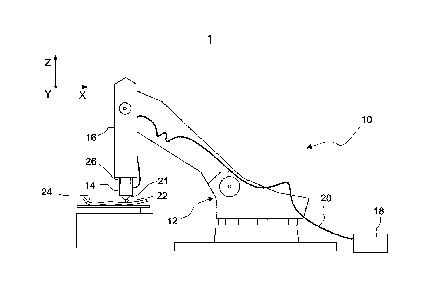
Figure 1, in a schematic representation, shows a laser
machining apparatus 10, having a robot 12, and having a
machining head 14 according to the invention, which is
attached to a movable arm 16 of the robot 12.
CA 02898903 2015-07-29
17242.9 17
The laser machining apparatus 10 additionally includes a
laser beam source 18, which, in the embodiment
represented, is realized as a disc laser. Such lasers
generate laser radiation having a wavelength in the order
of magnitude of 1 pm. By means of an optical fibre 20,
laser radiation 21 generated by the laser beam source 18
is supplied to the machining head 14, and is focussed by
the latter in a focal spot 22 for the purpose of
machining a workpiece 24.
The workpiece 24, which, in the embodiment represented,
is to be cut by the laser machining apparatus 10, is a
curved panel of a fibre-reinforced plastic. These are
composed of an organic matrix, which is reinforced either
with carbon fibres (carbon-fibre plastics) or with glass
fibres (glass-fibre plastics). Such panels may be used,
for example, to produce particularly light automobile
body shells. In principle, such panels can also be welded
to each other or to metals. In the following, it is
assumed that the workpiece 24 is to be cut by means of
the laser machining apparatus 10.
In the case of cutting, the distance between the focal
spot 22 and the machining head 14 is usually only a few
millimetres. As explained further below with reference to
Figure 2, the focal length of focussing optics contained
in the machining head 14 is variable, to enable the focal
spot 22 to be moved in the Z direction in relation to the
machining head, and thereby to enable it to be tracked
18
rapidly upon variations in the distance between the
machining head 14 and the workpiece 24. It is only when
the focal spot 22 has been optimally positioned in
relation to the workpiece 24 that the workpiece 24 is cut
through without edge damage.
To ensure that the focal spot 22 is always optimally
positioned in relation to the workpiece 24, the machining
head 14 has an integrated optical coherence tomograph 26,
which continuously measures the distance between the
machining head 14 and the workpiece 24, in proximity to
the focal spot 22.
2. Structure of the machining head
Figure 2 shows the structure of the machining head 14, in
a schematic section along the optical axis OA of
focussing optics 28, which are represented here with only
one lens, but which may also comprise a plurality of
lenses or mirrors.
The machining head 14 has a housing 30, which is divided
by partitions 32, 34 into a measuring portion 36, a
middle portion 38 and an end portion 40. During the
operation of the laser machining apparatus 10, the laser
radiation 21 emerges from the end of the optical fibre
20, which is located in the middle portion 38. This laser
radiation is collimated by a collimator lens 42 and
deflected, via a planar deflection mirror 44, in the
Date Recue/Date Received 2021-10-20
CA 02898903 2015-07-29
17242.9 19
direction of the end portion 40. The collimated laser
radiation 21 is then incident upon the focussing optics
28, passes through a protective glass 46, which is
realized as a plane-parallel plate and embedded in the
partition 34, and is finally focussed in the focal spot
22. The axial position of the focal spot 22 along the Z
axis can be varied by moving the focussing optics 28, as
is indicated in Figure 2 by a double arrow 48. A
positioning drive 50, which is controlled by a control
unit 52 of the machining head 14, is provided to move the
focussing optics 28.
The end portion 40 of the housing 30, which is separated
off from the middle portion 38 by the partition 34 and
the protective glass 46, has an inlet opening 54 for a
pressurized process gas, which may be, for example, air.
The type of process gas used depends on the nature of the
laser machining operation and on the material to be
machined. In the case of cutting of workpieces from
glass-fibre reinforced plastic, the process gas merely
performs the function of removing melted-on material from
the kerf. In the case of other types of laser machining
operations, for instance welding of metals, the process
gas may also react chemically with the workpiece.
The process gas emerges from the end portion 40 though an
opening 55 in a nozzle 56, which is interchangeably
mounted at the lower end of the machining head 14, and
through which the laser radiation 21 also emerges. The
CA 02898903 2015-07-29
17242.9 20
nozzle 56, which may be made, for example, of copper, has
a conical circumferential surface 57 and a likewise
conical bore 58, which is concentric with the
circumferential surface 57 and which has an inner face
60, as can also be seen in the enlarged detail
representation on the left in Figure 2. The opening angle
of the conical bore 58 matches the numerical aperture of
the laser radiation 21, such that the laser radiation 21
cannot be incident upon the inner face 60 of the nozzle
56.
The nozzle 56 is part of the end portion 40 of the
housing 30. Its bore 58, together with the volume
enclosed by the end portion 40, constitutes an interior
61, through which the laser radiation 21 passes.
As can be seen in the enlarged representation on the left
in Figure 2, during the laser machining operation the
focussed laser radiation 21 is incident upon the surface
of the workpiece 24, and causes the material of the
workpiece 24 to melt and partially vaporize. If the focal
spot 22 is optimally positioned in relation to the
workpiece 24, and the laser radiation 21 is matched, in
respect of intensity and wavelength, to the material of
the workpiece 24, a smooth cut edge, along which the
workpiece 24 is parted through, is produced at the level
of the focal spot 22.
CA 02898903 2015-07-29
17242.9 21
During the laser machining operation, in addition to the
laser radiation 21, the pressurized process gas, supplied
through the inlet opening 54, also emerges from the
interior 61, through the bore 58 and the end opening 55
thereof, and is incident upon the surface of the
workpiece 24.
Since workpieces such as, for instances, body shells in
automobile construction, are generally not planar, but
have an irregular three-dimensional form, the distance
between the workpiece 24 and the machining head 14 varies
continuously during the machining of the workpiece. In
order to ensure a constant machining distance, therefore,
the machining head 14 must be tracked continuously by the
robot 12, not only along the desired kerf, but also in
the Z direction perpendicular thereto. In addition or as
an alternative to this tracking in the Z direction that
is effected by the robot 12, the focussing optics 28 may
be moved, in order always to position the focal spot 22
at the optimum height relative to the workpiece 24.
In order for the focal spot 22 always to be optimally
positioned in relation to the workpiece 24, by means of
the robot 12 and/or the focussing optics 28, the
machining head 14 comprises an optical coherence
tomograph 26, most of which is accommodated in the
measuring portion 36 of the housing 30. The function of
the coherence tomograph 26 is to continuously measure the
distance of the workpiece 24 in relation to the machining
22
head 14 during the laser machining operation. For this
purpose, the coherence tomograph 26 has a broadband light
source 64, a first beam splitter 66, and a second beam
splitter 68, after which the beam path splits into an
object arm 70 and a reference arm 72.
In the object arm 70, measuring light 65 generated by the
light source 64, after emerging from an optical fibre, is
directed on to an axicon 71, which has a conical inlet
face 74 and a planar outlet face 76. Measuring light 65,
emerging in a divergent manner from the fibre of the
object arm 70, is deflected outwards by the axicon 71,
such that the measuring light 65 widens in the form of a
ring after the axicon 71. The measuring light 65 passes
through a converging lens 78, passes the outer contour of
the deflecting mirror 44, and is ultimately incident upon
the focussing optics 28, by which the measuring light 65
is also focussed. In the embodiment represented, the
focal plane of the measuring light 65 is further from the
machining head 14 than is the focal plane of the laser
radiation 21. Since, owing to the passage through the
axicon 71, the measuring light 65 passes in the form of a
ring through the optical elements arranged after the
latter, the region 75 illuminated on the workpiece by the
measuring light 65 is also in the form of a ring, as is
illustrated by Figure 3.
At the end of the reference arm 72, the reference light
73, which is initially guided there in an optical fibre,
Date Recue/Date Received 2021-10-20
23
is reflected by a planar mirror 77 coupled back into the
optical fibre of the reference arm 72.
The coherence tomograph 26 additionally includes a
spectrally resolving light sensor 79, which senses the
interference of measuring light 65 that has been
reflected from the workpiece 24, by means of the
reference light 73, which has traversed a similar optical
path distance in the reference arm 72.
In the embodiment represented, the coherence tomograph 26
operates in the frequency domain (FD-OCTM, Fourier Domain
Optical Coherence Tomograph). Such coherence tomographs
make use of the effect whereby differing path length
differences between the object arm 70 and the reference
arm 72 produce differing oscillation frequencies in the
interference signal. Each layer of a sample can therefore
be assigned a particular frequency in the interference
signal. Since the light sensor 79 resolves the intensity
of the interference signal, the depth information can be
deduced, by way of the Fourier transformation, from the
spectrally resolved interference signal. Thus, by means
of a single FD-OCT measurement, the entire depth profile
at a point is obtained, without the necessity of tuning
the geometric length of the reference arm or the
wavelength of the light source. Since such coherence
tomographs 26 are known in the prior art, their function
is not explained in greater detail here. Also suitable,
Date Recue/Date Received 2021-10-20
CA 02898903 2015-07-29
17242.9 24
in principle, are coherence tomographs having optical
circulators, as described in DE 10 2010 016 862 B2.
The light sensor 79 thus generates an output signal, from
which the control unit 52 can deduce the actual distance
between the machining head 14 and the workpiece 24 from
which the measuring light 65 has been reflected. The
control unit compares the actual distance with a
specified distance d, and controls the positioning drive
50 of the focussing optics 28, by way of a feedback
control loop, such that the actual distance approximates
as closely as possible to the specified distance d during
the entire laser machining operation. Alternatively or
.
additionally, the control unit 52 may also act upon the
control system of the robot 12.
As already mentioned, during the laser machining
operation the process gas passes through the interior 61,
through which the laser radiation 21 and the measuring
light 65 also pass. Since the laser machining operation
is a dynamic process, in which the conditions in
proximity to the surface of the workpiece 24 change
continuously, the flow conditions of the process gas also
vary as it flows through the interior 61 and ultimately
emerges from the opening 55. Even if no turbulence
occurs, pressure fluctuations of the process gas in
regions of approximately laminar flows are generally
unavoidable.
CA 02898903 2015-07-29
17242.9 25
The pressure fluctuations also involve fluctuations of
the refractive index of the process gas, and this
especially affects the accuracy of the distance
measurement. Thus, if the process gas has, for example, a
pressure of 5 bar at a first instant and of 1 bar at a
second instant, then the distance values measured by the
coherence tomograph 26 differ by more than 0.7 mm, if the
distance between the protective glass 46 and the opening
55 is about 25 cm. For a high-precision distance
measurement, these falsifications of the measured
distances, resulting from the pressure fluctuations in
the interior 61 are too great to be acceptable.
In order to compensate these falsifications, it is
therefore provided, according to the invention, to direct
a portion of the measuring light 65, not on to the
workpiece 24, but on to a reflective annular face 80 that
is located at the lower end of the nozzle 56, in the bore
58. As can be seen in the enlarged representation on the
left in Figure 2, for this purpose the bore 58 is
realized as a stepped bore, the step, having the thereby
formed reflective annular face 80, being in immediate
proximity to the opening 55. The reflective annular face
80 is inclined such that the measuring light 65 incident
thereon, which in Figure 2 is highlighted in bold, is
reflected into itself, as indicated by the double arrows.
Since the position of the reflective annular face 80 does
not alter, the portion of the measuring light 65 that is
reflected by it thus directly measures the optical path
CA 02898903 2015-07-29
17242.9 26
length differences that are caused by pressure
fluctuations in the interior 61. In order to distinguish
the portions of the measuring light 65 that are reflected
by the workpiece 24 and by the annular face 80, and also
to distinguish them from each other in their
designations, the portion reflected by the workpiece 24
is also referred to in the following as the object beam
65a, and the proportion reflected by the annular face is
also referred to as the measuring beam 65b.
io Shown schematically in Figure 4 is a graph, in which the
distance values, calculated by Fourier transformation
from the interference signal by the control unit 52, are
represented in a simplified form. IL is to be assumed
that the object beam 65a, at a first instant Li, measures
a distance dw(t1), and at a subsequent instant t2 > ti
measures a distance d(t2) > dw(ti), although during this
time interval the distance between the workpiece 24 and
the machining head 14 has remained unchanged. The
apparent increase in the distance by Ow(t2) - d(t1) is
due to the increase in pressure in the interior 61.
However, this increase in the pressure is measured by the
measuring beam 65b, which is reflected at the stationary
annular face 80 in the nozzle 56. The measuring beam 65b
thus measures a distance that would always have to remain
constant, without pressure fluctuations, because the
reflective annular face 80 is stationary. Owing to the
pressure increase between the instants t1 and t2,
CA 02898903 2015-07-29
17242.9 27
however, the measuring beam 65b is also subjected to an
increase in the optical path length, as a result of which
the distance measured by it apparently increases from
dr(ti) to dr(t2) > dr(t1).
In order to compensate falsifications of the measured
workplace distance d, that have been caused by pressure
fluctuations in the interior 61, it is therefore merely
necessary to correct the measured values d, by those
fluctuations that are measured by the measuring beam 65b.
The value d,' for the workpiece distance, compensated by
the pressure fluctuations, is thus obtained as
(t2) = d( t2) - [ (dr (t2) - dr (ti)
The thus measured values for the workpiece distance may
be used, on the one hand, to track the focussing optics
28, by means of the positioning drive 50, such that the
focal spot 22 is located at the desired location on or in
the workpiece 24. Alternatively or additionally, the thus
measured values may also be used to control the measured
distance itself by feedback control. This ensures that
the process gas can emerge as evenly as possible from the
nozzle 56, and that the removed material is reliably
cleared from the kerf by the process gas.
CA 02898903 2015-07-29
17242.9 28
3. Further embodiments
a) Nozzle without stepped bore
Figure 5, in a sectional representation based on Figure
2, shows a machining head 14 according to another
embodiment. In this figure, components that are the same
or that correspond to each other are denoted by the same
reference numerals.
The machining head 14 from Figure 5 differs from the
machining head shown in Figure 2 substantially in that
the axicon 71 has been replaced by a hollow cylinder 82
made of glass (a full cylinder is also a possibility for
this). That portion of the measuring light 65 that
emerges from the optical fibre of the object arm 70 and
passes through the hollow cylinder 82, without having
been reflected at its wall, is collimated by the
converging lens 78, and focussed by the focussing optics
28 into the focal spot 22 of the laser radiation 21. This
portion constitutes an object beam 65a having a circular
cross section, which here detects the distance between
the workpiece 24 and the machining head 14, not outside
of the optical axis OA, but along it.
Since the focal spot 22 is located on the optical axis OA
and the workpiece 24 is being parted-off there, the
distance values supplied by the object beam 65a are less
suited for effecting distance feedback control on the
CA 02898903 2015-07-29
17242.9 29
basis thereof. However, an axial measuring point makes it
possible to identify whether or not the parting-off of
the workpiece 24 by means of the laser radiation 21 has
been successful. This is because a successful parting-off
is manifested by an abrupt increase in the measured axial
distance, or also by an absence of the distance signal.
The portion of the measuring light 65 reflected by total
reflection at the wall of the hollow cylinder 82
surrounds, in the shape of a ring, the region of the
focussing optics 28 and of the protective glass 46
through which the laser radiation 21 passes, as is also
the case, similarly, in the embodiment shown in Figure 2.
This portion constitutes a measuring beam 65b, which,
however, as can be seen in the enlarged representation on
the left in Figure 5, is not reflected into itself at a
full-perimeter step of the bore 58. Instead, the
measuring beam 65b is deflected multiply at the conical
inner face 80' of the bore 58, such that the incoming and
the outgoing measuring light 65b have a mirror-
symmetrical beam path in each meridional plane. As a
result, the measuring beam 65b that has been reflected
from the inner face 80' of the bore 58 is coupled back
into the optical fibre of the object arm 70, jointly with
the reflected object beam.
This beam path of the measuring beam 65b has the
advantage that the bore 58 in the nozzle 56 need not be
provided with a step, but can retain the usual conical
CA 02898903 2015-07-29
17242.9 30
shape. Otherwise, however, the measuring principle does
not differ from that of the embodiment described in
Figures 2 to 4.
b) Reference beam passes through interior
Figure 6 shows a variant of a machining head 14, in which
the reference light 73 itself passes through the interior
61, in which the pressure fluctuations result in
falsifications of the distance measurement, and thereby
constitutes the measuring beam 65b. Moreover, in the case
lo of this embodiment, the measuring light 65 does not pass
through any parts of the optics that are located in the
light path of the laser radiation 21. Instead, the
measuring light 65 is provided with its own measuring-
light optics 84, which direct the measuring light 65 on
to the workpiece 24 and a reflective face 80" in the
nozzle 56.
This is explained in the following with reference to
Figure 7, which is an enlarged representation of the end
portion 40 of the housing 30 with the components
contained therein. The measuring optics 84 comprise two
converging lenses, which focus the light emerging from an
optical fibre. The larger portion 65a of the light is
focussed on to the face of the workpiece 24, and again
constitutes the object beam 65a, which measures the
distance in relation to the workpiece 24. A smaller
portion of the light, highlighted in bold, constitutes
CA 02898903 2015-07-29
17242.9 31
the measuring beam 65b, and simultaneously constitutes
the reference light 73. The measuring beam 65b is
incident upon a reflective face 80" that is realized, in
the form of a small groove, immediately at the opening 55
of the nozzle 56. The measuring beam 65b, together with
the object beam 65a, goes back to the light sensor 79 of
the coherence tomograph 26 via the measuring-light optics
84.
In the case of this embodiment, therefore, unlike the two
embodiments previously described, no additional reference
arm is provided. Rather, the reference arm is constituted
by the light path between the beam splitter 66 and the
reflective face 80". In the light sensor 79 the measuring
beam 65b is overlaid directly with the object beam 65a,
thereby making it possible to deduce the difference in
optical path length that is traversed by the light
between the reflective face 80" and the surface of the
workpiece 24.
Since the measuring beam 65b highlighted in bold in
Figure 7, which simultaneously constitutes the reference
light 73, is subjected to practically the same pressure
fluctuations as the object beam 65a directed on to the
workpiece 24, optical path length differences that are
caused by pressure fluctuations in the interior 61 are
compensated automatically, since the pressure
fluctuations act in the same way upon the measuring beam
65b as upon the object beam 65a.
CA 02898903 2015-07-29
17242.9 32
This variant of the coherence tomograph 26 is expedient,
in particular, if a relatively large proportion of the
light focussed by the measuring-light optics 84 is
reflected at the reflective face 80", and thereby
constitutes the reference light of the coherence
tomograph. The more similar are the intensities of the
light reflected at the reflective face 80" and of the
light reflected at the workpiece 24, the more pronounced
are the interference phenomena that can be sensed by the
light sensor 79.
c) Plurality of measuring beams
Clearly, measuring light 65 can also be directed on to
the surface of the workpiece 24 from differing
directions, independently of each other, as illustrated
in Figure 8. In the case of this embodiment, two mutually
independent coherence tomographs are provided with
measuring-light optics 84, 84, which, by means of object
beams 65a, 65a', at a plurality of measurement points on
the workpiece 24, measure the distance thereof in
relation to the machining head 14, independently of each
other. An exemplary arrangement for the case of a total
of eight measuring beams is represented schematically in
Figure 9. The measurement points MP1 to MP8 surround the
focal spot 22 concentrically, such that even more complex
surface geometries of the workpiece 24 can be measured
almost completely.
CA 02898903 2015-07-29
17242.9 33
In the case of the embodiment represented in Figure 8,
the coherence tomographs are of a similar design to that
of the embodiment represented in Figures 6 and 7. The
reference arms are therefore each constituted by the
optical paths between a beam splitter and a reflective
face on the nozzle. Clearly, it is also possible to
combine coherence tomographs that are of a design similar
to those shown in Figures 2 to 4, and that thus each have
a reference arm located outside of the interior 61 in
which the pressure fluctuations occur.
A plurality of measuring beams can also be generated by
means of only one coherence tomograph. For this, it is
necessary only to ensure that the measuring beams
traverse distinctly differing optical paths to the
workpiece. The signals representing the distance are then
so far apart from each other that they can always be
assigned to a particular measuring beam.