Note: Descriptions are shown in the official language in which they were submitted.
CA 02898942 2016-10-12
. 74420-730
LAUNDRY TREATMENT APPARATUS WITH DRUM CONNECTED
TO MOTOR SHAFT
[0001]
FIELD
[0002] The- present disclosure relates to a laundry treatment apparatus, and
more
particularly, to a laundry treatment apparatus including a main washing device
and a
secondary washing device that is additionally provided in the main washing
device, so as to
treat laundry.
BACKGROUND
[0003] In general, laundry treatment apparatuses are appliances for washing
laundry
using, for example, detergent and mechanical friction.
[0004] Typical laundry treatment apparatuses may be directly installed
on the floor.
However, a front-loading type laundry treatment apparatus (referred to as a
"drum washing
machine"), which is one of such laundry treatment apparatuses that is
configured to load
laundry from the front, may have a relatively low insert port for inserting
the laundry. For
this reason, a user may have to bend his/her body when loading or unloading
laundry
through the insert port.
[0005] In some cases, a support may be added beneath the front-loading type
laundry treatment apparatus such that the laundry treatment apparatus is
positioned
vertically higher. In some cases, an additional, secondary washing device may
be installed
in the support and may be used to wash, for example, a small quantity of
laundry.
SUMMARY
[0006] According to one aspect, a laundry treatment apparatus for
treating laundry
includes a main washing device and a secondary washing device, wherein the
secondary
washing device includes a tub configured to receive wash water, a drum
rotatably provided
in the tub and configured to receive laundry, and a pulsator rotatably
provided in the drum
and configured to be rotated by motion of one or both of the wash water and
the laundry
that are received in the drum.
1
CA 02898942 2015-07-30
[0007] Implementations according to this aspect may include one or more of
the
following features. For example, the secondary washing device may further
include a
motor configured to rotate the drum, and the pulsator may be configured to,
based on the
drum being rotated by the motor, rotate in the same direction as a rotation
direction of the
drum. In some cases, the pulsator may be configured to, based on the rotation
of the drum
stopping after a period of rotation, continue rotating in the same direction
as the previous
rotation direction of the drum for a predetermined time due to inertia.
[0008] In some examples, the secondary washing device may further include a
motor configured to rotate the drum, and a pulsator connector may be installed
between a
shaft of the motor and the pulsator, the pulsator connector being configured
to transfer a
driving force of the motor to the drum without transferring the driving force
to the pulsator.
In these examples, the shaft of the motor may be coupled to a hub and
configured to transfer
the driving force of the motor to the drum, the pulsator connector may be
installed to the
hub and configured to rotate together with the hub, the pulsator may be
restricted from
vertically moving in the drum, and the pulsator may be engaged with the
pulsator connector
and configured to rotate about a circumference of the pulsator connector. In
some cases, the
pulsator may define a connection hole in a central portion of the pulsator, a
stepped portion
being formed on an inner peripheral surface of the connection hole, and the
pulsator
connector may include a vertical protrusion portion that forms a rotary shaft
of the pulsator,
a latch portion being engaged with the stepped portion to restrict vertical
movement of the
pulsator. The stepped portion may be configured such that the inner peripheral
surface of
the connection hole has a decreasing diameter toward a center of the
connection hole. The
latch portion may be fastened to an upper surface of the stepped portion, and
a
predetermined gap may be defined between the latch portion and the upper
surface of the
stepped portion. The latch portion may be configured as one or more latch
portions
provided along the inner peripheral surface of the connection hole. In some
cases, a mesh
cap may be provided at an upper side of the connection hole, and the mesh cap
may define a
plurality of holes having a predetermined size, the plurality of holes being
configured to
perform a filtering function.
[0009] In some implementations, the pulsator may include a body rotatably
provided on a bottom surface of the drum, and one or more blades protruding
upward from
the body. In some cases, the blades may extend outward from a center of the
body, and the
body and blades of the pulsator may be integrated with each other. The
secondary washing
device may be a drawer type washing device configured to be inserted in and
withdrawn
2
81790254
from the laundry treatment apparatus. In some cases, the laundry treatment
apparatus
according to this aspect may further include a first cabinet defining an
external appearance of
the main washing device and a second cabinet defining an external appearance
of the
secondary washing device. The first and second cabinets may be integrated with
each other.
[0009a] There is also provided a laundry treatment apparatus for treating
laundry
including: a tub configured to receive wash water; a drum rotatably provided
in the tub and
configured to receive laundry; a pulsator rotatably provided in the drum and
configured to be
rotated by motion of one or both of the wash water and the laundry that are
received in the
drum, a motor configured to rotate the drum; a hub configured to connect to a
shaft the motor
and connect to the drum to transfer the driving force of the motor; and a
pulsator connector
installed on the hub and configured to rotate together with the hub, wherein
the pulsator is
engaged with the pulsator connector and configured to separately rotate about
a circumference
of the pulsator connector, wherein the pulsator connector is configured to
transfer a driving
force of the motor to the drum without transferring the driving force to the
pulsator.
[0009b] Another aspect provides a washing device for treating laundry that is
configured to be placed under a laundry treatment apparatus, wherein the
washing device
comprises: a tub configured to receive wash water; a drum rotatably provided
in the tub and
configured to receive laundry; a pulsator rotatably provided in the drum and
configured to be
rotated by motion of one or both of the wash water and the laundry that are
received in the
drum, a motor configured to rotate the drum; and a pulsator connector
installed between a
shaft of the motor and the pulsator, wherein the shaft of the motor is
connected to the drum
and is separated from the pulsator, wherein the pulsator connector is
configured to transfer a
driving force of the motor to the drum without transferring the driving force
to the pulsator.
BRIEF DESCRIPTION OF THE DRAWINGS
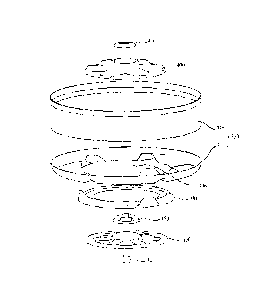
[0010] FIG. 1 is a perspective view illustrating an example laundry treatment
apparatus;
[0011] FIG. 2 is a cross-sectional view schematically illustrating the example
laundry
treatment apparatus shown in FIG. 1;
3
CA 2898942 2017-06-02
CA 02898942 2016-10-12
= 74420-730
[0012] FIG. 3 is a perspective view illustrating an example secondary washing
device
of the laundry treatment apparatus;
[0013] FIG. 4 is an exploded perspective view of the example secondary washing
device illustrated in FIG. 3;
[0014] FIG. 5 is a transverse cross-sectional view of the example secondary
washing
device illustrated in FIG. 3;
[0015] FIG. 6 is an enlarged cross-sectional view of the example secondary
washing
device illustrated in FIG. 5;
100161 FIG. 7A is a perspective view illustrating an example of a coupled
state
between a hub and a pulsator connector; and
[0017] FIG. 7B is perspective cross-sectional view illustrating an example of
a
coupled state between the pulsator connector and a pulsator.
DETAILED DESCRIPTION
[0018] FIGS. 1 and 2 show an example laundry treatment apparatus according to
an
implementation of the present disclosure.
[0019] Referring to FIGS. 1 and 2, the laundry treatment apparatus, which is
designated by reference numeral 100, may include a main washing device 200 and
a
secondary washing device 300. The secondary washing device 300 may be provided
to one
side of or beneath the main washing device 200. In addition, the main washing
device 200
may include a first cabinet 210 defining the external appearance thereof, and
the secondary
washing device 300 may include a second cabinet 310 defining the external
appearance
thereof. In some cases, the first and second cabinets 210 and 310 may be
integrally formed. In
some cases, the laundry treatment apparatus 100 according to the
implementation of the
3a
CA 02898942 2015-07-30
present disclosure may be configured of only the main washing device 200 or
may be
configured of only the secondary washing device 300.
[0020] The main washing device 200 may be a front-loading type washing device.
In this case, a door 250 is installed at the front of the main washing device
200, and laundry
may be inserted into the main washing device through the door 250.
[0021] Specifically, the main washing device 200 may include a first
cabinet 210
defining the external appearance thereof, a first tub 220 which is provided in
the first
cabinet 210 to store wash water, and a first drum 230 which is rotatably
arranged in the first
tub 220 to receive laundry. The first drum 230 may be rotated by a first motor
240 provided
outside the first tub 220 in the first cabinet 210. For instance, a first
shaft 241 of the first
motor 240 may be connected to the rear surface of the first drum 230 through
the rear
surface of the first tub 220. Accordingly, the driving force of the first
motor 240 may be
transferred to the first drum 230 through the first shaft 241.
[0022] In addition, one or more lifters 231 may be installed on the inner
peripheral
surface of the first drum 230 in order to tumble the laundry accommodated in
the first drum
230. In addition, the first cabinet 210 may include a water supply section 110
for supplying
wash water to the first tub 220 and a second tub 320 of the secondary washing
device 300,
which will be described later, a drainage section 120 for discharging the wash
water from
the first and second tubs 220 and 320 after washing is completed, and the
like.
[0023] The water supply section 110 may include a water supply pump and a
water
supply pipe, and the drainage section 120 may have a drainage pump and a
drainage pipe.
In addition, the water supply section 110 may be connected to a supply line
111 through
which wash water is supplied from an external water source of the laundry
treatment
apparatus. The wash water supplied to the water supply section 110 may be
supplied to the
first tub 220 via a detergent container 260 along a first line 112, or may be
selectively
supplied to the second tub 320 of the secondary washing device 300 along a
second line 113.
In order to selectively supply the wash water to the first and second tubs 220
and 320, first
and second valves 114 and 115 may be provided on the first and second lines
112 and 113,
respectively. For instance, the first valve 114 may open and close the first
line 112, and the
second valve 115 may open and close the second line 113.
[0024] In some cases, one or more dampers 270 may be installed between the
first
cabinet 210 and the first tub 220 in order to absorb vibration transferred to
the first tub 220
by the rotation of the first drum 230. In addition, a damper (e.g. a cylinder
damper) may be
installed between the first tub 220 and the cabinet of the secondary washing
device 300. In
4
CA 02898942 2015-07-30
this case, each of the dampers 270 may be a spring damper or a cylinder
damper. In
addition, a control panel 280 for operating the main washing device 200 may be
provided at
the front upper side of the first cabinet 210.
[0025] The secondary washing device 300 may be arranged adjacent to the main
washing device 200. For example, the secondary washing device 300 may be
provided
beneath the main washing device 200, to thereby improve the convenience of a
user
utilizing the main washing device 200. That is, the secondary washing device
300 may
improve convenience for the user utilizing the main washing device 200 by
allowing the
main washing device 200 to be installed at a high position.
[0026] In some cases, when the secondary washing device 300 is provided
together
with the main washing device 200 to wash laundry, the main and secondary
washing
devices 200 and 300 may have the same washing capacity. Alternatively, one of
the main
and secondary washing devices 200 and 300 may have a lower capacity than the
other, in
consideration of the installation space and manufacturing costs of the laundry
treatment
apparatus 100.
[0027] As illustrated in FIGS. 1 and 2, the secondary washing device 300 may
be
configured such that at least one of a washing capacity, a volume, and a
height is lower than
that of the main washing device 200 in the implementation. Consequently, the
user may
appropriately select and use one of the main and secondary washing devices 200
and 300
according to the amount of laundry.
[0028] The user may select and use one of the main and secondary washing
devices
200 and 300 according to the type of laundry. For example, laundry such as
baby's clothing
or underwear, which needs to be separated for washing, or small amounts of
laundry may be
washed using the secondary washing device 300, while other types of laundry
may be
washed using the main washing device 200.
[0029] As illustrated, the secondary washing device 300 may be a top-
loading type
washing device. Alternatively, the secondary washing device 300 may be a
drawer type
washing device, the components of which are inserted into or withdrawn from
the second
cabinet 310. For example, the secondary washing device 300 may include a
second cabinet
310 defining the external appearance thereof, a drawer housing 360 which is
inserted into or
withdrawn from the second cabinet 310, a second tub 320 which is provided in
the drawer
housing 360 to store wash water, and a second drum 330 which is rotatably
arranged in the
second tub 320 to accommodate laundry. In addition, a drainage section for
discharging the
wash water may be provided at one side of the second tub 320.
CA 02898942 2015-07-30
[00301 The drawer housing 360 may be inserted into or withdrawn from the
second
cabinet 310 through an opening portion 350 formed in the second cabinet 110
toward the
front of the laundry treatment apparatus 100.
[00311 The second drum 330 may be rotated by a second motor 340 provided
outside the second tub 320 in the drawer housing 360. That is, a second shaft
341 of the
second motor 340 may be connected to the rear surface of the second drum 330
through the
rear surface of the second tub 320. Accordingly, the driving force of the
second motor 340
may be transferred to the second drum 330 through the second shaft 341.
[0032] In some cases, a cover panel 361 may be installed at the front of
the drawer
housing 360. The cover panel 361 may be formed integrally with the drawer
housing 360.
In addition, the cover panel 361 may be formed with a handle 362 for inserting
and
withdrawing the drawer housing 360. A control panel 380 for operating the
secondary
washing device 300 may be provided on the upper surface of the cover panel
361. In
addition, a supply hole 365, through which wash water is supplied to the
second tub 320,
and a door 363, through which laundry is inserted into or removed from the
second drum
330, may be formed in the upper portion of the drawer housing 360.
[00331 Referring to FIG. 3, the secondary washing device 300 may include a
pulsator 400 which is rotatably provided at the central portion of the second
drum 300, in
addition to the drawer housing 360, the second tub 320 provided in the drawer
housing 360,
and the second drum 330 rotatably arranged inside the second tub 320, which
are described
above. In addition, a mesh cap 410 for filtering out foreign substances such
as lint, which
may be contained in wash water, may be installed at the central portion of the
pulsator 400.
A plurality of holes 411 having a predetermined size may be formed in the mesh
cap 410,
and the mesh cap 410 may be fixed to the pulsator 400 so as to rotate along
with the rotation
of the pulsator 400.
[0034] In addition, one or more drum blades 332 may be provided at a base
331 of
the second drum 330. That is, the drum blades 332 may protrude upward from the
base 331
of the second drum 330. In some cases, the drum blades 332 formed at the base
331 of the
second drum 330 may extend toward the outer periphery of the second drum 330.
A
plurality of drum blades 332 may be spaced apart by a predetermined distance
(i.e. a
predetermined angular distance) at the base 331 of the second drum 330. Thus,
when the
second drum 330 rotates, the drum blades 332 may generate a vortex of wash
water in the
second drum 330 so as to prevent laundry from tangling and improve washing
efficiency.
6
CA 02898942 2015-07-30
[0035] In some cases, a plurality of holes 333 may be formed in the base
331 of the
second drum 330. Through the holes 333 formed in the base 331, the wash water
accommodated in the second tub 320 may flow into the second drum 330 or the
wash water
in the second drum 330 may flow out to the second tub 320. In some cases, a
plurality of
holes may be defined in the side of the second drum 330.
[0036] The pulsator 400 may include a pulsator body 401 and one or more
pulsator
blades 402. A plurality of pulsator blades 402 may protrude upward from the
pulsator body
401, and may be spaced apart by a predetermined distance. In addition, the
pulsator blades
402 may extend toward the outer periphery of the pulsator body 401. Thus, when
the
pulsator 400 rotates, the pulsator blades 402 may generate a vortex of wash
water in the
second drum 330 so as to prevent laundry from tangling and improve washing
efficiency.
[0037] The pulsator 400, which will be specifically described later, may
operatively
rotate due to friction with at least cme of wash water and laundry, which are
accommodated
in the second drum 330 to rotate along with the rotation of the second drum
330. In other
words, the motion of one or both of wash water and laundry can cause the
pulsator 400 to
rotate.
[0038] Referring now to FIGS. 2 and 4, the second drum 330 may include a drum
body 335 and a drum base 331 coupled to the lower side of the drum body 335.
In addition,
the driving force (i.e. rotational force) of the second motor 340 may be
transferred to the
second drum 330 through the second shaft 341. As illustrated, a hub 390 is
coupled to the
upper side of the second shaft 341, and a connection flange 391 is installed
between the
drum base 331 and the hub 390. Accordingly, the driving force of the second
motor 340
may be transferred to the drum base 331 through the second shaft 341, the hub
390, and the
connection flange 391. As a result, the second drum 330 can be rotated.
[0039] The drum base 331 may have an opening portion 336 which is defined in
the
central portion thereof for installation of the pulsator 400 therethrough. In
addition, a
pulsator connector 450 may be installed to the hub 390. That is, the pulsator
connector 450
may be installed at the upper central portion of the hub 390, and the pulsator
connector 450
may also rotate along with the rotation of the hub 390.
[0040] For example, the pulsator 400 can be engaged with the pulsator
connector
450, which is installed to the upper side of the hub 390, through the opening
portion 336
formed in the drum base 331 of the second drum 330. In this case, although the
hub 390
and the pulsator connector 450 may be rotated by the driving of the second
motor 340, the
pulsator 400 is engaged with the pulsator connector 450 such that the driving
force of the
7
CA 02898942 2015-07-30
second motor 340 is not transferred to the pulsator 400. The pulsator
connector 450 may be
engaged with the pulsator 400 so as to restrict only the vertical movement of
the pulsator
400. That is, the pulsator 400 may circumferentially rotate about the pulsator
connector 450
even though the pulsator connector 450 is engaged with the pulsator 400.
[0041] For example, when the second drum 330 is rotated by the second motor
340,
the pulsator 400 may rotate in the same direction as the rotation direction of
the second
drum 330 due to friction with at least one of wash water and laundry which
rotate in the
second drum 330 in the same direction as the rotation direction of the second
drum 330. In
addition, when the rotation of the second drum is stopped following a period
of rotation, the
pulsator 400, which rotates in the same direction as the rotation direction of
the second
drum 330, may continue to rotate in the same direction as the rotation
direction of the
second drum 330 for a predetermined time due to inertia. That is, the pulsator
connector
450 may be installed between the second shaft 341 of the second motor 340 and
the pulsator
400 such that the driving force of the second motor 340 is transferred only to
the second
drum 330 through the second shaft 341, the hub 390, and the connection flange
391.
[0042] Referring to FIGS. 5 and 6, one side of the second shaft 341, to
which the
driving force of the second motor is transferred, may be connected the hub
390. In addition,
the pulsator connector 450 may be connected to the upper side of the hub 390.
Accordingly,
when the second motor rotates, the hub 390 and the pulsator 400 can rotate
together in the
same direction as the rotation direction of the second motor. As described
above, the
driving force of the second motor may be, of course, transferred to the second
drum 330
through the connection flange 391 arranged between the drum base 331 and the
hub 390.
[0043] In this case, the pulsator 400 may be provided with a connection
hole 416.
Specifically, the connection hole 416 may be formed in the central portion of
the pulsator
400. For example, the connection hole 416 may be formed in the central portion
of the
pulsator body 401 so as to vertically penetrate the pulsator 400, and one or
more pulsator
blades 402 may extend toward the outer periphery of the pulsator body 401 from
the
connection hole 416. When the pulsator connector 450 is coupled to the
pulsator 400, at
least a portion of the pulsator connector 450 may be inserted into the
connection hole 416.
[0044] A stepped portion 420 may be formed on the inner peripheral surface of
the
connection hole 416 formed in the pulsator 400. In addition, the pulsator
connector 450
may has a vertical protrusion portion 451 which forms the rotary shaft of the
pulsator 400,
and a latch portion 452 which is engaged with the stepped portion 420.
Specifically, the
latch portion 452 of the pulsator connector 450 may serve to restrict the
vertical movement
8
CA 02898942 2015-07-30
of the pulsator 400. For example, the latch portion 452 may protrude toward
the inner
peripheral surface of the connection hole 416 formed in the pulsator 400.
Specifically, the
latch portion 452 may protrude upward from the upper surface of the stepped
portion 420.
[0045] In this case, a predetermined gap may be defined between the
vertical
protrusion portion 451 of the pulsator connector 450 and the inner peripheral
surface of the
stepped portion 420. In addition, a predetermined gap may be defined between
the latch
portion 452 and the upper surface of the stepped portion 420. This enables the
pulsator 400
to freely rotate about the pulsator connector 450 while the rotation of the
pulsator connector
450 is not transferred to the pulsator 400.
[0046] Thus, the driving force of the second motor 340 can be transferred
to the
pulsator connector 450 through the second shaft 341 and the hub 390, but not
transferred to
the pulsator 400. That is, since the predetermined gap is defined between the
vertical
protrusion portion 451 of the pulsator connector 450 and the inner peripheral
surface of the
stepped portion 420, the rotation of the pulsator connector 450 may not be
transferred to the
pulsator 400. For example, the pulsator connector 450 restricts the vertical
movement of
the pulsator 400, whereas it does not restrict the circumferential rotation of
the pulsator 400.
[0047] That is, since the circumferential rotation of the pulsator 400 is
not restricted
by the pulsator connector 450, the pulsator 400 may rotate due to friction
with at least one
of wash water and laundry accommodated in the second drum 330. In addition,
the pulsator
400, which begins to rotate due to friction with at least one of wash water
and the laundry,
may continue to rotate in the same direction for a predetermined time due to
inertia even
though the rotation of the second drum 330 is stopped.
[0048] In some cases, the mesh cap 410 may be installed to the upper side
of the
connection hole 416, and the holes 411 having the predetermined size may be
formed in the
mesh cap 410 so as to perform a filtering function.
[0049] Hereinafter, the structure in which the pulsator 400 is rotatably
coupled to
the pulsator connector 450 will be described with reference to FIGS. 7A and
7B. FIG. 7A
illustrates an example coupled state between the hub and the pulsator
connector, and FIG.
7B is illustrates the example coupled state between the pulsator connector and
the pulsator.
[0050] Referring to FIGS. 7A and 7B, the rotational force of the second motor
340
may be transferred to the hub 390 through the second shaft 341 connected to
the second
motor 340. The pulsator connector 450 may be coupled to the upper side of the
hub 390.
That is, the pulsator connector 450 may include a connector body 453, a
vertical protrusion
portion 451 which protrudes upward from the connector body 453, and a latch
portion 452
9
CA 02898942 2015-07-30
which protrudes outward from the free end of the vertical protrusion portion
451. In some
cases, the connector body 453, the vertical protrusion portion 451, and the
latch portion 452
may be integrally formed.
[0051] The pulsator connector 450 may have a plurality of ribs protruding
upward
from the connector body 453, and at least a portion of the ribs may form the
vertical
protrusion portion 451. The vertical protrusion portion 451 may be configured
as a plurality
of vertical protrusion portions, and the vertical protrusion portions 451 may
be spaced apart
from each other by a predetermined distance (i.e. a predetermined angular
distance). In
addition, the latch portion 452, which protrudes laterally from the pulsator
connector 450,
may be provided at the free end of each vertical protrusion portion 451. For
example, the
latch portion 452 may be provided at the free end of the vertical protrusion
portion 451, and
may protrude toward the outer periphery of the pulsator connector 450.
[0052] In some cases, the pulsator 400 may be formed with the connection hole
416
for accommodating the vertical protrusion portion 45 1 of the pulsator
connector 450. The
connection hole 416 may vertically penetrate the pulsator 400. Specifically,
the connection
hole 416 may be formed in the central portion of the pulsator 400. In
addition, the stepped
portion 420 may be formed on the inner peripheral surface of the connection
hole 416.
[0053] The stepped portion 420 may protrude such that the inner peripheral
surface
of the connection hole 416 has a decreasing diameter toward the center of the
connection
hole 416. In some cases, the inner peripheral surface of the connection hole
416 may be
divided into a first inner peripheral surface 412, which is formed above the
stepped portion
420, and a second inner peripheral surface 413 on which the stepped portion
420 is formed.
That is, the inner peripheral surface of the stepped portion 420 may form the
second inner
peripheral surface 413. In this case, the second inner peripheral surface 413
may have a
smaller diameter than that of the first inner peripheral surface 412, due to
the stepped
portion 420.
[0054] When the
pulsator 400 is rotatably coupled to the pulsator connector 450,
the vertical protrusion portion 451 of the pulsator connector 450 is inserted
through the
connection hole 416 formed in the pulsator 400. For example, the vertical
protrusion
portion 451 is inserted through the lower side of the connection hole 416, so
that the
pulsator 400 may be coupled to the pulsator connector 450. In addition, the
holes 411 may
be formed in the upper side of the connection hole 416 to be covered by the
mesh cap 410
for performing a filtering function.
CA 02898942 2015-07-30
[0055] In this case, the latch portion 452 formed at the free end of the
vertical
protrusion portion 451 has an inclined surface 454, thereby enabling the
vertical protrusion
portion 451 to be inserted through the lower side of the connection hole 416.
Specifically,
the connection hole 416 is divided by an upper frame 415 and a lower frame
414, and the
outer peripheral surface of the latch portion 452 has a larger diameter than
that of the inner
peripheral surface of the lower frame 414. For example, an upper frame 415 and
a lower
frame 414 dividing the connection hole 416 may be classified into the upper
side and the
lower side on the basis of the stepped portion 420. In addition, the inner
peripheral surface
of the upper frame 415 may have a larger diameter than that of the inner
peripheral surface
of the lower frame 414.
[0056] When the pulsator 400 is coupled to the pulsator connector 450, the
lower
frame 414 at the lower side of the connection hole 416 may slide along the
guide surface of
the latch portion 452 so that the vertical protrusion portion 451 and the
latch portion 452 of
the pulsator connector 450 are inserted into the connection hole 416. That is,
when the
pulsator 400 is coupled to the pulsator connector 450, the lower frame 414 at
the lower side
of the connection hole 416 may push the guide surface of the latch portion 452
toward the
center of the connection hole 416 so that the vertical protrusion portion 451
and the latch
portion 452 are inserted into the connection hole 416. In order to couple the
pulsator 400 to
the pulsator connector 450, the vertical protrusion portion 451 provided at
the pulsator
connector 450 may be made entirely or in part of a flexible material, for
example plastic.
[0057] When the pulsator 400 is coupled to the pulsator connector 450, the
latch
portion 452 of the pulsator connector 450 may be engaged with the stepped
portion 420
formed on the inner peripheral surface of the connection hole 416.
Specifically, the latch
portion 452 of the pulsator connector 450 may protrude toward the inner
peripheral surface
of the connection hole 416, and may be disposed on an upper portion 421 of the
stepped
portion 420. That is, the latch portion 452 may be caught by the upper surface
421 of the
stepped portion 420. For example, the latch portion 452 may be arranged such
that the
lower surface of the latch portion 452 faces the upper surface 421 of the
stepped portion 420.
In addition, a predetermined gap may be defined between the latch portion 452
and the
upper surface 421 of the stepped portion 420.
[0058] Accordingly, the pulsator connector 450 may restrict the vertical
movement
of the pulsator 400. For example, the connector body 453 of the pulsator
connector 450
may restrict the downward movement of the pulsator 400, and the latch portion
452 of the
pulsator connector 450 may restrict the upward movement of the pulsator 400.
11
CA 02898942 2015-07-30
[0059] The vertical protrusion portion 451 provided at the pulsator
connector 450
may be configured as a plurality of vertical protrusion portions, and the
vertical protrusion
portions 451 may be spaced apart by a predetermined distance in the
circumferential
direction corresponding to the inner peripheral surface (i.e. the second inner
peripheral
surface) of the connection hole 416 formed in the pulsator 400.
[0060] In this case, since the latch portion 452 protrudes toward the inner
peripheral
surface of the connection hole 416 from the free end of each vertical
protrusion portion 451,
the outer peripheral surface of the vertical protrusion portion 451 may have a
smaller
diameter than that of the outer peripheral surface of the latch portion 452.
In addition, the
inner peripheral surface (i.e. the second inner peripheral surface) of the
stepped portion 420
may have a larger diameter than that of the outer peripheral surface of the
vertical
protrusion portion 451. That is, a predetermined gap may be defined between
the inner
peripheral surface of the stepped portion 420 and the outer peripheral surface
of the vertical
protrusion portion 451. Through the gap defined between the inner peripheral
surface of the
stepped portion 420 and the outer peripheral surface of the vertical
protrusion portion 451, it
is possible to prevent or minimize friction caused between the inner
peripheral surface of
the stepped portion 420 and the outer peripheral surface of the vertical
protrusion portion
451 when the pulsator 400 rotates about the pulsator connector 450.
[0061] The first inner peripheral surface 412 of the connection hole 416 may
have a
larger diameter than that of the outer peripheral surface of the latch portion
452. That is, a
predetermined gap may be defined between the first inner peripheral surface
412 of the
connection hole 416 and the outer peripheral surface of the latch portion 452.
Through the
gap defined between the first inner peripheral surface 412 of the connection
hole 416 and
the outer peripheral surface of the latch portion 452, it is possible to
prevent or minimize
friction caused between the first inner peripheral surface 412 of the
connection hole 416 and
the outer peripheral surface of the latch portion 452 when the pulsator 400
rotates about the
pulsator connector 450.
[0062] As described above, it may be possible to prevent or minimize the
friction,
which is caused between the pulsator connector 450 and the pulsator 400 in the
rotation
direction of the pulsator 400 or in the direction opposite thereto, when the
pulsator 400
rotates.
[0063] For instance, the vertical movement of the pulsator 400 may be
restricted by
the pulsator connector 450, but the pulsator 400 may rotate about the pulsator
connector 450.
12
CA 02898942 2015-07-30
[0064] In other words, the driving force of the second motor 340 may not be
transferred to the pulsator 400 even though the pulsator connector 450 is
rotated by the
driving of the second motor 340. The pulsator 400 may rotate due to friction
with at least
one of wash water and laundry, which are accommodated in the second drum 330
to rotate
along with the rotation of the second drum 330.
[0065] In addition, the pulsator 400, which begins to rotate due to
friction with at
least one of wash water and laundry in the second drum 330, may continue to
rotate for a
predetermined time due to inertia even though the rotation of the second drum
330 is
stopped. Similarly, the pulsator 400 may continue to rotate due to inertia
even when the
rotation direction of the second drum 330 is reversed.
[0066] The driving of the pulsator 400 will be described below in detail.
When the
second drum 330 is rotated by the second motor 340, the wash water and laundry
accommodated in the second drum 330 rotate along with the rotation of the
second drum
330 in the rotation direction of the second drum 330.
[0067] Friction may be generated between the wash water and laundry and the
pulsator 400 which is freely and rotatably provided in the second drum 330,
thereby
enabling the pulsator 400 to also rotate in the rotation direction of the
second drum 330. In
addition, the pulsator 400 may continue to rotate for a predetermined time due
to inertia
even though the rotation of the second drum 300 is stopped. Thus, since the
vortex of the
wash water can be generated by the pulsator 400, it can be possible to prevent
laundry from
tangling and improve washing efficiency.
[0068] In order to improve washing efficiency, the second drum 330 may rotate
in
one direction for a predetermined time, and may then rotate in the other
direction. In this
case, even when the pulsator 400 rotates in one direction due to friction with
at least one of
wash water and laundry and the second drum 330 rotates in the other direction,
the pulsator
400 may continue to rotate in the one direction for a predetermined time due
to inertia.
[0069] In some cases, an interval may occur during which the second drum 330
and
the pulsator 400 rotate in opposite directions. That is, the second drum 300
and the pulsator
400 may rotate in opposite directions for a predetermined time due to the
inertia of rotation
of the pulsator 400. in this case, since the vortex of the wash water is also
generated by the
pulsator 400, it may be possible to prevent laundry from tangling and improve
the washing
efficiency.
[0070] Furthermore, in accordance with the structure of the present
disclosure,
since there is no need for components such as the clutch which selectively
transfers the
13
CA 02898942 2015-07-30
driving force of the second motor 340 to the pulsator 400, the secondary
washing device
300 can have a compact structure, compared to a washing device having a
clutch. In
addition, the manufacturing costs of the secondary washing device 300 can be
reduced, and
power consumption of the secondary washing device 300 may be reduced.
[0071] In accordance with the present disclosure, since additional
components such
as a clutch that selectively transfers the driving force of a motor to a drum
and a pulsator
may be omitted, a laundry treatment apparatus (particularly, a secondary
washing device)
can have a compact structure.
[0072] In addition, since the clutch is not required, the secondary washing
device
can have a simple structure compared to when having a clutch, and the overall
manufacturing costs of the laundry treatment apparatus can be reduced.
[0073] In addition, since the motor provided in the secondary washing device
rotates only the drum of the secondary washing device, power consumption may
be reduced
compared to the case where the drum and the pulsator are driven together by a
single motor.
[0074] It will be apparent to those skilled in the art that various
modifications and
variations can be made in the present disclosure without departing from the
spirit or scope
of the disclosures. Thus, it is intended that the present disclosure covers
the modifications
and variations of this disclosure provided they come within the scope of the
appended
claims and their equivalents.
14