Note: Descriptions are shown in the official language in which they were submitted.
CA 02899138 2015-07-23
WO 2014/118219
PCT/EP2014/051702
1
Underwater Node for Seismic Surveys and Method
BACKGROUND
TECHNICAL FIELD
[0001] Embodiments of the subject matter disclosed herein generally
relate to
methods and systems and, more particularly, to mechanisms and techniques for
performing a marine seismic survey using underwater nodes that carry
appropriate
seismic sensors.
lo
DISCUSSION OF THE BACKGROUND
[0002] Marine seismic data acquisition and processing generate a
profile
(image) of a geophysical structure under the seafloor. While this profile does
not
provide an accurate location of oil and gas reservoirs, it suggests, to those
trained in
the field, the presence or absence of these reservoirs. Thus, providing a high-
resolution image of geophysical structures under the seafloor is an ongoing
process.
[0003] Reflection seismology is a method of geophysical exploration
to
determine the properties of earth's subsurface, which is especially helpful in
the oil
and gas industry. Marine reflection seismology is based on using a controlled
source of energy that sends the energy into the earth. By measuring the time
it
takes for the reflections to come back to plural receivers, it is possible to
evaluate the
depth of features causing such reflections. These features may be associated
with
subterranean hydrocarbon deposits.
CA 02899138 2015-07-23
WO 2014/118219
PCT/EP2014/051702
2
[0004] A traditional system for generating seismic waves and
recording their
reflections off geological structures present in the subsurface is illustrated
in Figure
1. A vessel 10 tows an array of seismic receivers 11 provided on streamers 12.
The
streamers may be disposed horizontally, i.e., lying at a constant depth
relative to the
ocean surface 14. The streamers may be disposed to have other than horizontal
spatial arrangements. The vessel 10 also tows a seismic source array 16
configured
to generate a seismic wave 18. The seismic wave 18 propagates downward toward
the seafloor 20 and penetrates the seafloor until eventually a reflecting
structure 22
(reflector) reflects the seismic wave. The reflected seismic wave 24
propagates
upward until it is detected by the receiver 11 on the streamer 12. Based on
the data
collected by the receiver 11, an image of the subsurface is generated by
further
analyses of the collected data. The seismic source array 16 includes plural
individual source elements.
[0005] However, this traditional configuration is expensive because
the cost of
the streamers is high. In addition, this configuration might not provide
accurate
results because coupling between seismic receivers and the sea water is poor
for s-
waves. To overcome this last problem, new technologies deploy plural seismic
sensors on the bottom of the ocean to improve the coupling.
[0006] One such new technology is ocean bottom station (OBS) nodes.
OBSs
are capable of providing better data than conventional acquisition systems
because
of their wide-azimuth geometry. Wide-azimuth coverage is helpful for imaging
beneath complex overburdens such as those associated with salt bodies. Salt
bodies act like huge lenses, distorting seismic waves propagating through
them. To
image subsalt targets, it is preferable to have the capability to image
through
CA 02899138 2015-07-23
WO 2014/118219
PCT/EP2014/051702
3
complex overburdens, but even the best imaging technology alone is not enough.
Good illumination of the targets is necessary. Conventional streamer surveys
are
operated with a single seismic vessel and have narrow azimuthal coverage. If
either
the source or the receiver is located above an overburden anomaly, the
illumination
of some targets is likely to be poor. OBS nodes can achieve wide-azimuth
geometry
and solve this problem.
[0007] Additionally, OBS nodes are more practical in the presence of
obstacles such as production facilities. For the purpose of seismic monitoring
with
repeat surveys (4D), OBSs have better positioning repeatability than
streamers.
io Also, OBSs provide multi-component data that can separate up- and down-
going
waves at the seabed, which is useful for multiple attenuations and for imaging
using
the multiples. In addition, multi-component data allows for recording shear
waves,
which provides additional information about lithology and fractures, and
sometimes
allows for imaging targets that have low reflectivity or which are under gas
clouds.
[0008] U.S. Patent no. 6,932,185, the entire content of which is
incorporated
herein by reference, discloses an OBS. In this case, the seismic sensors 60
are
attached, as shown in Figure 2 (which corresponds to Figure 4 of the patent),
to a
heavy pedestal 62. A station 64 that includes the sensors 60 is launched from
a
vessel and arrives, due to its gravity, at a desired position. The station 64
remains
on the ocean bottom permanently. Data recorded by sensors 60 is transferred
through a cable 66 to a mobile station 68. When necessary, the mobile station
68
may be brought to the surface to retrieve the data.
CA 02899138 2015-07-23
WO 2014/118219
PCT/EP2014/051702
4
[0009] Although this method provides a better coupling between the
seabed
and the sensors, the method is still expensive and not flexible because the
stations
and corresponding sensors are left on the seabed.
[0010] An improvement to this method is described, for example, in
European
Patent No. EP 1 217 390, the entire content of which is incorporated herein by
reference. In this document, a sensor 70 (see Figure 3) is removably attached
to a
pedestal 72 together with a memory device 74. After recording the seismic
waves,
the sensor 70 and memory device 74 are instructed by a vessel 76 to detach
from
the pedestal 72 and rise to the ocean surface 78 to be picked up by the vessel
76.
[0011] However, this configuration is not very reliable because the
mechanism
maintaining the sensor 70 connected to the pedestal 72 may fail to release the
sensor 70. Also, the sensor 70 and pedestal 72 may not reach their intended
positions on the ocean bottom. Further, leaving the pedestals 72 behind
contributes
to ocean pollution and increases survey cost, which are both undesirable.
[0012] A further improved autonomous ocean bottom node seismic recording
device (Trilobit node disclosed in U.S. Patent no. 7,646,670, the entire
content of
which is incorporated herein by reference) having an integrated modular design
and
one or more features that assist coupling of the unit to the seafloor and
improve the
azimuthal fidelity of seismic signal measurement (vector fidelity) has been
developed
by the assignee of the present patent application. An example of a Trilobit
node 400
is shown in Figure 4. The node 400 has a base plate 402 holding various
components, including a signal recording unit housing 404 and two battery
housings
406. A hydrophone 408 is positioned in the center of the vector sensor housing
410.
The vector sensor housing may also include geophones. Also shown in Figure 4
is a
CA 02899138 2015-07-23
WO 2014/118219
PCT/EP2014/051702
handle 412 which allows for removal of the recording unit from the device, a
clamp
414 which allows for securing of the recording unit when installed in the
device, and
a fixed connector 416, located at the rear of the signal recording unit
housing, to
allow for a communication connection between the recording unit and other
5 components of the device.
[0013] However, even this node has its own limitations, e.g., the
node needs
to be returned to the vessel for the data to be removed, and the batteries
need to be
charged. Because the batteries are fixedly attached to the base plate, the
charging
process may take a number of hours, during which time the node cannot be used.
io [0014] Accordingly, it would be desirable to provide systems
and methods that
provide a marine node for recording seismic waves that can be retrieved on the
vessel and readied for a next deployment in a short period of time.
SUMMARY
[0015] According to one exemplary embodiment, there is a marine node for
recording seismic waves underwater. The node includes a first module
configured to
house a seismic sensor; bottom and top plates attached to the first module; a
second
module removably attached to the first module and configured to slide between
the
bottom and top plates, the second module including a first battery and a first
data
storage device; and a third module removably attached to the first module and
configured to slide between the bottom and top plates, the third module
including a
second battery.
[0016] According to another exemplary embodiment, there is a marine
node
for recording seismic waves underwater. The node includes a chassis; bottom
and
CA 02899138 2015-07-23
WO 2014/118219
PCT/EP2014/051702
6
top plates attached to the chassis; a first module configured to slide between
the top
and bottom plates to removably attach to the chassis and configured to house a
seismic sensor; and a second module configured to slide between the top and
bottom plates to removably attach to the chassis and configured to house a
battery.
The battery provides electrical power to the seismic sensor.
[0017] According to still another exemplary embodiment, there is a
method for
seismically surveying a subsurface. The method includes a step of placing a
node
on the ocean bottom, the node including a first module configured to house a
seismic
sensor, bottom and top plates attached to the first module, a second module
io removably attached to the first module and configured to slide between
the bottom
and top plates, the second module including a first battery and a data storage
device, and a third module removably attached to the first module and
configured to
slide between the bottom and top plates, the third module including a second
battery;
a step of recording seismic data with the seismic sensor; a step of storing
the
seismic data in the data storage device; a step of retrieving the node from
water; a
step of replacing the first and second modules with corresponding modules
having
their batteries charged; and a step of redeploying the node for further
seismic data
acquisition.
BRIEF DESCRIPTION OF THE DRAWINGS
[0018] The accompanying drawings, which are incorporated in and
constitute
a part of the specification, illustrate one or more embodiments and, together
with the
description, explain these embodiments. In the drawings:
CA 02899138 2015-07-23
WO 2014/118219
PCT/EP2014/051702
7
[0019] Figure 1 is a schematic diagram of a conventional seismic
survey
system;
[0020] Figure 2 is a schematic diagram of a station that may be
positioned on
the ocean bottom for seismic data recording;
[0021] Figure 3 is a schematic diagram of another station that may be
positioned on the ocean bottom for seismic data recording;
[0022] Figure 4 is a schematic diagram of an ocean bottom node;
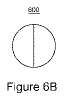
[0023] Figures 5A and 5B illustrate an ocean bottom node having
replaceable
batteries and a data storage device according to an exemplary embodiment;
lo [0024] Figures 6A and 6B illustrate another ocean bottom node
having
replaceable batteries and a data storage device according to an exemplary
embodiment;
[0025] Figures 7A-D illustrate still another ocean bottom node having
replaceable batteries and a data storage device according to an exemplary
embodiment;
[0026] Figures 8A-D illustrate various means for keeping various
components
of a node together according to an exemplary embodiment; and
[0027] Figure 9 is a flowchart of a method for deploying and
recovering a node
according to an exemplary embodiment.
DETAILED DESCRIPTION
[0028] The following description of the exemplary embodiments refers
to the
accompanying drawings. The same reference numbers in different drawings
identify
the same or similar elements. The following detailed description does not
limit the
CA 02899138 2015-07-23
WO 2014/118219
PCT/EP2014/051702
8
invention. Instead, the scope of the invention is defined by the appended
claims. The
following embodiments are discussed, for simplicity, with regard to the
terminology and
structure of an ocean bottom node having seismic sensors and being deployed
underwater for performing seismic recordings.
[0029] Reference throughout the specification to "one embodiment" or "an
embodiment" means that a particular feature, structure or characteristic
described in
connection with an embodiment is included in at least one embodiment of the
subject
matter disclosed. Thus, the appearance of the phrases "in one embodiment" or
"in an
embodiment" in various places throughout the specification is not necessarily
referring
io to the same embodiment. Further, the particular features, structures or
characteristics
may be combined in any suitable manner in one or more embodiments.
[0030] New marine seismic surveys need a system of seismic nodes that
can
be deployed in shallow water, used to record seismic waves, and then recovered
and quickly readied for a new deployment. These nodes need to be compact and
easy to manipulate. Also, these nodes need to have their data downloaded and
the
batteries replaced in the shortest time possible. A novel node that fulfills
these
requirements is described herein. The node has separate compartments for a
recording unit and sensors, batteries and data storage. These compartments may
be sandwiched between two coupling plates. The compartments and their masses
are distributed to maintain the symmetry necessary for vector fidelity. The
batteries
and data storage units are easily removable to allow the node to be placed
back in to
service almost immediately after recovery. Replacement batteries and data
storage
are swapped with the used ones in a matter of minutes. Thus, the node is ready
for
a new mission while the used batteries are recharging, and the original data
storage
CA 02899138 2015-07-23
WO 2014/118219
PCT/EP2014/051702
9
unit is processed to download the recorded data. The node is light and
compact,
enabling deployment in large quantities from smaller vessels used in shallow-
water
operations. Such a node may advantageously be used in areas where it is too
congested or too sensitive to use ocean-bottom cables or towed streamers.
[0031] According to an exemplary embodiment, such a node has one or more
seismic sensors. The seismic sensors may include at least one of a hydrophone,
geophone, accelerometers, electromagnetic sensors, etc. If an electromagnetic
sensor is used, then a source that emits electromagnetic waves may be used
instead or in addition to an acoustic source.
[0032] According to an exemplary embodiment illustrated in Figure 5A, a
node
500 includes a housing 502 that might have a cylindrical shape. Bottom plate
506
and top plate 504 may be attached to the housing 502 to fully enclose the
inside
components. The inside components may include a recording and sensors unit 508
and one or more batteries 510a and 510b. The recording and sensors unit 508,
as
shown in Figure 5B, may include one or more seismic sensors 530, a data
storage
device 532, a processor 534 for controlling data collection and storage, a
device
(e.g., a GPS synchronized clock) 536 for generating a time stamp for the
recorded
data, etc. All these components may be in the recording and sensors unit 508.
The
recording and sensors unit 508 may be configured to be attached to the bottom
plate
506. The recording and sensors unit 508 may also include connectors 540a and
540b for electrically connecting to batteries 510a and 510b. Thus, batteries
510a
and 510b are removably attached to the recording and sensors unit 508. Figure
5A
also shows that the housing 502 has one or more holes 550 for allowing water
to
enter in a limited space inside the housing where one or more sensors are
located.
CA 02899138 2015-07-23
WO 2014/118219
PCT/EP2014/051702
In another application, one or more sensors (e.g., hydrophone 552) are
positioned in
the hole(s) 550 for measuring seismic waves and no water enters the housing
502.
[0033] In one exemplary embodiment illustrated in Figure 5B, when the
node
500 is brought on the vessel, the top plate 504 is removed (clamping mechanism
5 520 and 522 may be used to keep the top plate 504 attached to the housing
502,
e.g., screws, magnets, etc.), the recording and sensors unit 508 and batteries
510a
and 510b are removed, and a new set of recording and sensors unit and
batteries
are attached to the base plate. The top plate is then reattached to the
housing and
the node is ready (e.g., in a matter of minutes) for a new mission.
lo [0034] In another exemplary embodiment, only batteries 510a and
510b and
the data storage device 532 are removed from the node 500. In other words, the
sensor units and the processor remain within the housing 502 for a next
mission. In
one application, the batteries and the storage device can be removed without
removing the top plate, e.g., through corresponding holes either in the
housing 502
or the top plate 504.
[0035] In still another exemplary embodiment illustrated in Figure
6A, a
sandwich-type node 600 is presented. The node 600 has a chassis 602 to which a
bottom plate 604 is attached. A top plate 606 may be removably attached to the
chassis 602. Two modules 608 and 610 are configured to slide between the top
and
bottom plates to electrically connect to each other, as discussed later. The
modules
may be designed to weigh the same so the node's weight is symmetrically
distributed along vertical axis Z (see Figure 6B). The first module 608 may
include a
sensor pack 620 (including one or more sensors, e.g., a hydrophone and three
geophones), a recording unit 621, and a storage device 622. The recording unit
621
CA 02899138 2015-07-23
WO 2014/118219
PCT/EP2014/051702
11
may include electronics necessary for processing electrical signals from the
sensor
pack, e.g., digitizing them. The storage device 622 may be of any type used in
the
art for storing data. The sensor pack 620 may include a hydrophone 623 that
fluidly
communicates with an ambient (e.g., water) of the node through a hole 603
formed
in the first module's housing. In this way, either the water enters the
housing freely
and is in direct contact with the hydrophone or the hydrophone exits the
housing to
contact the water. The first module 608 may also include, as noted above, a
processor, an interface 624 for receiving power and exchanging data with the
second module 610, and other customary equipment for a node (e.g.,
lo communication interfaces, GPS synchronized clock, etc., as illustrated
in Figure 5B).
[0036] The second module 610 may include a battery 630 connected to
an
interface 632. The interface 632 may be configured to electrically connect to
the
interface 624 of the first module 608. The interfaces 632 and 624 are
waterproof. In
another application, an optional battery 634 may be located in the first
module 608,
and a storage module 640 may be located in the second module 610.
[0037] The two modules 608 and 610 may be detachably attached to the
chassis 602 and/or the bottom and top plates. Methods and means for detachably
attaching modules to each another are known in the art and also described in
Figures 8A-D.
[0038] In another exemplary embodiment illustrated in Figures 7A-C, a node
700 has three modules 702, 704 and 706 sandwiched between top plate 710 and
bottom plate 712. The first module 702 (recorder and sensors module) includes
sensors 720 and 722 (e.g., a hydrophone and a geophone) and a recording unit
724
connected to the sensors and configured to receive and process (e.g.,
digitize)
CA 02899138 2015-07-23
WO 2014/118219
PCT/EP2014/051702
12
electrical signals from the sensors. The recording unit 724 may include a
storage
device for temporarily storing the seismic data until it is sent to the data
storage
device to be discussed later. The recorder and sensors module 702 is removably
attached to one or both plates 710 and 712 by known means, e.g., a clip 726.
[0039] The second module 704 (battery and data module) includes, besides a
battery 730, a data storage device 732 capable of permanently storing the data
processed by the recording unit 724. A wired and/or wireless interface 734 may
also
be located inside the battery and data module 704 for transferring the
recorded data
to the vessel when the module is retrieved on the vessel. If a wired interface
is used,
a port (not shown) is placed on the outside of the battery and data module.
[0040] The battery and data module 704 has a second port 736
configured to
electrically connect to a corresponding port (not shown) on the recorder and
sensors
module 702 to provide electric power and also to transfer data from the
recording
unit 724 to the data storage device 732.
[0041] The third module 706 includes a battery 740 connected to a port (not
shown) that electrically connects to a corresponding port 742 (waterproof
connector)
of the recorder and sensors module 702 for providing power. The recorder and
sensors module 702 may include a processor or controller 744 for coordinating
which module supplies power to the recorder and sensors module 702 at any
given
time. Also, the controller 744 may coordinate with the recording unit 724 for
transmitting seismic data to the data storage device 732. Optionally, the
third
module 706 may also include a data storage device 750 for storing data
recorded by
the seismic sensors. In this case, the controller 744 decides when data is
stored in
the data storage device 732 or in the data storage device 760. For example,
the
CA 02899138 2015-07-23
WO 2014/118219
PCT/EP2014/051702
13
controller may store data in a first storage unit until that storage is full
and then
switch the storage to the second storage unit. Alternatively, the controller
may store
the data in the first storage unit and back up that data into the second
storage unit.
As still another alternative, the controller may store the data in both the
first and
second storage units by interleaving it.
[0042] Having the second and third modules 706 and 708 symmetrical
(e.g.,
both including the same components) may provide the following advantage. When
the node is on the vessel and personnel need to quickly replace used batteries
with
new batteries, it may be more efficient to have two identical modules so
personnel
lo do not have to spend time identifying which sides of the node will
accept the second
and third modules. Also, for the same reason, it would be more efficient to
have a
single type of module stored on the vessel rather than two types. Further, if
the two
modules are identical, the entire node's weight is much easier to
symmetrically
distribute. Figure 7A shows possible shapes of the three modules. For example,
the
first module may be a rectangular cuboid, while the second and third modules
may
be half-cylinders.
[0043] Figure 7B shows that the modules 704 and 706 may have
symmetrical
shapes and sizes for balancing the node's weight so that, when delivered on
the
ocean bottom, the node is as stable as possible. Figure 70 shows a cross-
section of
the node 700, with Figure 7D showing the modules 704 and 706 being removed for
data transfer and/or recharging. By locating a data storage device 732 inside
the
battery and data module 704, the node 700 may be quickly prepared for a next
deployment because both the data and power source are replaced during a single
operation. In other words, the node does not have to be connected to a data
CA 02899138 2015-07-23
WO 2014/118219
PCT/EP2014/051702
14
network for downloading the data, thus requiring the node to stay for a long
time on
the vessel. As soon as the battery and data module is replaced with a new
module,
the node is ready to be redeployed.
[0044] Figures 8A-8D show various approaches for fixing the battery
and data
modules to the node. Figure 8A shows a node 800 configured similarly to the
node
shown in Figure 7A. The second and third modules 704 and 706 can be removably
attached to the first module by using, for example, attaching devices 802 to
808. In
this particular embodiment, there are two attaching devices per module and the
attaching devices may be clamps.
[0045] In another embodiment, Figure 8B shows a band 810 having at least
one clamp 812 and this assembly may be used, as shown in Figure 80, to lock in
place the second and third modules 704 and 706. The band 810 may be made of
metal, plastic, polymer, etc. Alternatively, a tire-like sleeve 820 may be
slipped over
the node when fully assembled to prevent the modules from coming apart. The
sleeve 820 may have a hole 822 that corresponds to the hole 721 in the first
module
702 to freely allow water to contact the hydrophone. The sleeve may be made of
polyurethane or other similar material. In one application, a combination of
the
above approaches may be used to lock the modules to the node.
[0046] The following considerations are equally valid for any of the
above-
discussed embodiments. Any of the above-discussed modules that include a
recording unit may have a pressure-sealed recording unit that houses multi-
channel
(1 to 4 or more) seismic recording devices, a high-accuracy clock synchronized
by
GPS or other means to time-stamp samples as they are recorded, and a number of
sensor devices to measure the data to be recorded. Examples of such sensors
are
CA 02899138 2015-07-23
WO 2014/118219
PCT/EP2014/051702
three components of seafloor velocity, three components of seafloor
acceleration,
separately or in conjunction with at least one hydrophone to measure the
seismic
pressure field in the water column. Other sensors types envisioned include,
for
example, temperature, salinity, water particle velocity, electromagnetic
signals, etc.
5 [0047] The recording unit is removably mounted to a chassis
(e.g., chassis
602 and base plate 604) that in turn can couple to the seafloor to
mechanically
connect the sensors to the seafloor to accurately measure seafloor motion.
This
chassis also allows the hydrophone to be exposed to the water column to
accurately
record the seismic pressure signal. Further, the chassis may provide the
necessary
10 coupling means for other sensors included in the recording unit.
[0048] The recording unit may be sandwiched between two circular
plates that
provide the necessary coupling to accurately measure seafloor motion. The
plates
may have other shapes, e.g., rectangular, hexagonal, etc. The distribution of
mass
within the assembled node is designed to maintain the natural symmetry of a
circular
15 plate or other symmetrical shape. This symmetrical distribution is
considered to
improve vector fidelity. The aspect ratio (height/base diameter) of the node
may be
kept low to optimize stability and avoid rocking moments when the node is
subjected
to sea-bottom currents.
[0049] Further, the mass may be distributed such that the node can be
adequately coupled when landing on either of its flat surfaces. Furthermore,
the
edges or tether attachment (used to attach the node to an autonomous
underwater
vehicle) of the node may be designed so that it preferably lands on either of
its flat
surfaces, rather than on its side. Alternatively, the nodes may be distributed
individually or connected to each other in "strings" using, chains, ropes,
cables, etc.
CA 02899138 2015-07-23
WO 2014/118219
PCT/EP2014/051702
16
in order to accelerate deployment and retrieval. The recording device has one
or
more waterproof connectors (e.g., 736) to allow power to be supplied to it and
for
data recorded to be transferred to a storage device (e.g., 732).
[0050] In addition, the recording unit may have a device for two-way
communication to an external configuration and clock synchronization unit that
is
used to program the recording unit in preparation for a recording session, or
after
such session to re-synchronize the clock and check the data. Such
communication
device may be a connector, Wi-Fi, optical, or other two-way communication
interfaces.
[0051] The node, as already discussed, may include one or more removable
battery packs. The battery pack is pressure-sealed and has a waterproof
connector
that can mate to a similar receptacle on the recording unit or chassis. Thus,
when
these units are engaged and held in the node chassis, the recording unit
receives
power from the battery pack. The removable battery pack can be recharged in a
charging station to be ready for the next deployment. Alternatively, the
battery pack
may be single-use and disposable.
[0052] Preferably, the node and recording unit utilize two
rechargeable battery
packs arranged symmetrically and within the circumference of the two circular
plates.
Further, a removable data storage device is provided. This device may be a
solid-
state memory or other device that can receive and store recorded data from the
recording unit in a temporary (non-volatile) manner with, or preferably
without, the
need for a power source. The data storage device is connected to the recording
unit
via a pressure-sealed connection. The recorded data from the seismic recording
unit
is stored on this data storage device during the recording session, while the
CA 02899138 2015-07-23
WO 2014/118219
PCT/EP2014/051702
17
recording unit and sensors are active. The data is stored until the data
storage
device is disconnected from the recording unit and connected to a downloading
terminal, at which time the data is moved to a permanent storage location for
further
handling and analysis. The data storage device can then be cleared (i.e.,
erased)
once a good-quality copy of the data is verified. At this time, the data
storage device
is ready to be connected to another node chassis and recording unit to start
another
recording session.
[0053] In one application, the data storage device is embedded within
one or
more of the battery units such that the connections to the recording unit for
data and
for power are through a common waterproof connector interface. Additionally,
while
downloading the data from the data storage device, the battery can be
recharged,
making the whole unit ready for re-deployment after this concurrent charging
and
downloading process is complete.
[0054] A complete node may also have the recording unit including
three
orthogonally-arranged velocity or acceleration sensors and one hydrophone, two
removable battery packs, at least one containing a data storage device, and
sandwiched between two circular coupling plates. In operation, a node chassis
with
recording unit and sensors is connected with one or two battery packs, at
least one
battery pack containing a data storage device.
[0055] In an exemplary embodiment illustrated in Figure 9, the node may be
configured in step 900 by a service unit (e.g., located on the vessel) that
uses a
direct connection or a wireless (e.g., Wi-Fi) interface, with the correct
recording
parameters for the project. In step 902, the internal clock of the node is
synchronized using GPS signals. In step 904, the node is deployed on the ocean
CA 02899138 2015-07-23
WO 2014/118219
PCT/EP2014/051702
18
bottom at a desired location. The node may be deployed by using a crane on the
vessel, if the water is shallow, or using an autonomous underwater vehicle
(AUV), a
submarine, or other means known in the art. In one application, plural nodes
are
connected to each other, i.e., "strung" together and deployed in this way. In
step 906
the recording is started and seismic data is collected. The GPS receiver
position
may be matched to the node's serial number and logged for future reference,
either
by manual entry, by barcode scan, by RFID reader or other means.
Alternatively,
the surface deployment point's position may be log using GPS and then estimate
the
nodes sub-surface positions. Once deployed and resting on the seabed, the
node's
position can be confirmed by direct arrival picking from the data or by
acoustic
transponder or other location techniques. The node remains on location during
the
programmed recording session. On completion of the recording session, the node
is
recovered in step 908 and the clock re-synchronized in order to calculate and
compensate for any clock drift during the recording session.
[0056] Once this task is completed, the batteries, including the data
storage
device, are disconnected in step 910 from the node chassis and connected to a
device that recharges the battery and downloads and checks the data. Meanwhile
the node chassis can be fitted in step 912 with other recharged and cleared
data
storage and made ready for re-deployment. Such an operational process ensures
a
minimum number of node chassis and recording units are necessary to conduct a
survey and their operating time is maximized.
[0057] The vector sensor used in the node may be, for example, one or
more
of a geophone, a piezo-electric accelerometer, a capacitive accelerometer, a
MEMS
accelerometer, a hydrophone accelerometer, one or more hydrophones, rotational
CA 02899138 2015-07-23
WO 2014/118219
PCT/EP2014/051702
19
sensors, etc. The rotation sensors may measure the pitch, roll and yaw
components
of the wave motion. The vector sensors measure the X, Y, Z translational
motions.
[0058] In one exemplary embodiment, the number of nodes is in the
hundreds
or thousands. Thus, a deployment vessel is configured to hold all of them at
the
beginning of the survey and then to launch them as the seismic survey is
advancing.
If a dedicated recovery vessel is used to recover the nodes, then the
deployment
vessel is configured to switch positions with the recovery vessel when the
deployment vessel becomes empty.
[0059] Although it is desired to keep the node simple and light,
various other
components may be implemented in the node if necessary. Such a component may
serve to provide communication between the node and a vessel (deployment,
recovery, or shooting vessel) and may be based on various technologies, i.e.,
acoustic waves, electromagnetic waves, etc. According to an exemplary
embodiment, a Hi PAP system may be used. The Hi PAP system may be installed
on any one of the participating vessels and may communicate with the acoustic
system of the node.
[0060] The Hi PAP system exhibits high accuracy and long-range
performance in both positioning and telemetry modes due to automatic beam-
forming transducers that focus the sensitivity toward its targets or
transponders.
This beam can not only be pointed in any direction below the vessel, but also
horizontally and even upward to the surface because the transducer is
spherical.
[0061] Thus, Hi PAP is a hydro-acoustic Super Short Base Line (SSBL)
or
USBL, towfish tracking system, able to operate in shallow and deepwater areas
to
proven ranges in excess of 3000 meters. It is a multi-purpose system used for
a
CA 02899138 2015-07-23
WO 2014/118219
PCT/EP2014/051702
wide range of applications, including towfish and towed platform tracking,
high-
accuracy subsea positioning, and telemetry and scientific research.
[0062] Another example of a unit that may be installed on the node is
an
inertial navigation system (INS). The INS may control a trajectory of the node
5 assuming that the node is provided with one or more motors that drive
corresponding
propellers and/or controllable fins.
[0063] The nodes illustrated in Figures 5A to 7D are advantageous for
shallow-water applications and to be manufactured and operated in high volume.
Utilization is higher because the intelligent (and costly) part of the node
can be kept
io in service (recording) independent of battery charging and data
downloading.
Compact design allows flexible deployment as a hybrid system with OBC or land
equipment or in a standalone operation.
[0064] One or more of the exemplary embodiments discussed above
disclose
a node configured to perform seismic recordings. It should be understood that
this
15 description is not intended to limit the invention. On the contrary, the
exemplary
embodiments are intended to cover alternatives, modifications and equivalents,
which are included in the spirit and scope of the invention as defined by the
appended claims. Further, in the detailed description of the exemplary
embodiments, numerous specific details are set forth in order to provide a
20 comprehensive understanding of the claimed invention. However, one
skilled in the
art would understand that various embodiments may be practiced without such
specific details.
[0065] Although the features and elements of the present exemplary
embodiments are described in the embodiments in particular combinations, each
CA 02899138 2015-07-23
WO 2014/118219
PCT/EP2014/051702
21
feature or element can be used alone without the other features and elements
of the
embodiments or in various combinations with or without other features and
elements
disclosed herein.
[0066] This written description uses examples of the subject matter
disclosed to
enable any person skilled in the art to practice the same, including making
and using
any devices or systems and performing any incorporated methods. The patentable
scope of the subject matter is defined by the claims, and may include other
examples
that occur to those skilled in the art. Such other examples are intended to be
within the
scope of the claims.
lo