Note: Descriptions are shown in the official language in which they were submitted.
CA 02899694 2015-07-29
DESCRIPTION
TITLE OF INVENTION
Infrared reflective film
TECHNICAL FIELD
[0001] The present invention relates to an infrared reflective film which is
used, mainly,
in a state of being disposed on an indoor side of a window glass. In
particular, the
present invention relates to an infrared reflective film having durability in
actual use
environments as well as excellent heat insulating property.
BACKGROUND ART
[0002] Theretofore, there has been known an infrared reflective substrate
configured by
disposing an infrared reflective layer on a backing such as glass or film. As
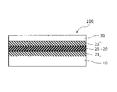
the
infrared reflective layer, a laminate obtained by alternately laminating a
metal layer and
a metal oxide layer is widely used. It functions to reflect near-infrared rays
such as
solar light to thereby impart heat insulating property. As the metal layer,
silver or the
like is widely used, from a viewpoint of enhancing a selective reflectivity in
the infrared
region. As the metal oxide layer, indium tin oxide (ITO) is widely used. The
metal
layer and the metal oxide layer are not sufficient in terms of physical
strength such as
abrasion-resistant. Moreover, they are apt to undergo degradation due to
external
environmental factors such as heat, ultraviolet rays, oxygen, water and/or
chlorine
(chloride ions). In view of this, generally, a protective layer is provided on
the infrared
reflective layer on a side opposite to the backing.
[0003] In late years, it has been attempted to reduce an emissivity of an
infrared
reflective film to provide enhanced heat insulating property. A key point for
reduction
in emissivity of an infrared reflective film is to effectively reflect far-
infrared rays
toward an indoor pace by a metal layer in an infrared reflective layer of the
infrared
reflective film. However, a film or a curable resin layer (hard coat layer)
used as a
protective film of the infrared reflective film generally contains a large
amount of a
1
CA 02899694 2015-07-29
compound comprising a C=C bond, a C=0 bond, a C-0 bond and an aromatic ring,
and
therefore exhibits large infrared vibrational absorption in a wavelength range
of 5 pm to
25 pin within a far-infrared region. Far-infrared rays absorbed by the
protective layer
are thermally diffused toward an outdoor space by heat conduction, without
being
reflected by the metal layer. Thus, when an amount of far-infrared rays
absorbed by
the protective layer becomes larger, the emissivity of the infrared reflective
film
increases, resulting in failing to obtain a heat insulating effect.
[0004] With a view to reducing emissivity of an infrared reflective film, the
following
Patent Document 1 proposes a technique of reducing an amount of far-infrared
rays to
be absorbed by a protective layer, wherein a cured material layer such as
cured
fluorosilane is used as a transparent protective layer, and a thickness of the
cured
material layer is set to be equal to or less than 500 nm.
CITATION LIST
[Patent Document]
[0005] Patent Document 1: pamphlet of WO 2011/109306A
SUMMARY OF INVENTION
[Technical Problem]
[0006] According to inventors' studies, it was found that, in the case where
the thickness
of the transparent protective layer is set to several hundred nm, as disclosed
in the
Patent Document 1, an optical film thickness of the transparent protective
layer overlaps
the wavelength range of visible rays, thereby causing a problem that the
infrared
reflective film is visually observed as colored with a rainbow-like pattern,
due to
multiple interference at an interlayer interface (rainbow-like coloring
phenomenon).
As means to prevent the rainbow-like coloring phenomenon, it is effective to
set the
thickness of the transparent protective layer to be less than the wavelength
range of
visible rays. However, if the thickness of the transparent protective layer is
reduced to
several ten nm, a protective effect of the protective layer deteriorates, so
that an infrared
reflective layer, particular, a metal layer therein, is more likely to undergo
degradation
2
CA 02899694 2015-07-29
such as oxidation, due to deterioration in durability thereof. The degradation
of the
metal layer is liable to cause deterioration in heat insulating property and
visible ray
transmittance of the infrared reflective film.
[0007] The Patent Document 1 also discloses an example where the transparent
protective layer is thinned to about 50 nm. In this example, in adjacent
relation to a
first metal layer such as silver in the infrared reflective layer, a highly-
durable second
metal layer such as Ni-Cr alloy is disposed to impart durability to the first
metal layer.
By adding the Ni-Cr alloy layer to the first metal layer, it is possible to
obtain an
infrared reflective film having durability, as well as heat shielding property
based on
reflection of near-infrared rays and heat insulating property based on
reflection of
far-infrared rays. However, the Ni-Cr alloy layer having a low visible ray
transmittance causes a problem that a visible ray transmittance of the
infrared reflective
film is reduced to about 50%.
[0008] Moreover, a curable organic material for forming the transparent
protective layer
generally has poor adhesion with respect to a metal oxide layer. Thus, when a
thickness of the transparent protective layer becomes smaller, there arises a
problem that
interlayer peeling between the metal oxide layer and the transparent
protective layer is
more likely to occur. As means to prevent the interlayer peeling, it is
conceivable to
additionally provide an adhesion layer, a primer layer or the like. However,
the
additional layer leads to an increase in amount of absorption of far-infrared
rays,
thereby causing another problem that the heat insulating property of the
infrared
reflective film deteriorates.
[0009] In view of the above, it is an object of the present invention to
provide an
infrared reflective film capable of exhibiting excellent heat insulating
property and high
durability by using a transparent protective layer having sufficient
durability and a
protective effect on an infrared reflective layer even when the transparent
protective
layer has a small thickness.
[Solution to Technical Problem]
[0010] As a result of studies, the inventors found that an infrared reflective
film
satisfying both durability and heat insulating property can be obtained by
using, as a
3
CA 02899694 2015-07-29
metal oxide layer disposed on a metal layer, a composite metal oxide
containing zinc
oxide and tin oxide, and allowing a transparent protective layer to contain a
given
compound, and have reached the present invention.
[0011] The present invention provides an infrared reflective film which is
configured by
disposing an infrared ray reflective layer and a transparent protective layer
on a
transparent film backing in this order. The infrared ray reflective layer
comprises: a
first metal oxide layer; a metal layer comprising a primary component
consisting of
silver; and a second metal oxide layer comprised of a composite metal oxide
containing
zinc oxide and tin oxide, which are arranged in this order from the side of
the
transparent film backing. The transparent protective layer lies in direct
contact with
the second metal oxide layer. The transparent protective layer is an organic
layer
having a cross-linked structure, wherein the cross-linked structure is
preferably derived
from an ester compound having an acidic group and a polymerizable functional
group in
the same molecule. As the ester compound, it is preferable to use an ester
compound
of a phosphoric acid with an organic acid having a polymerizable functional
group.
An amount of the ester compound-derived structure contained in the transparent
protective layer is preferably 1 to 40 weight%. Further, the transparent
protective layer
preferably has a thickness of 30 nm to 150 nm.
[0012] Preferably, in the infrared reflective film of the present invention, a
normal
emissivity as measured from the side of the transparent protective layer is
0.2 or less.
As long as the normal emissivity falls within this range, far-infrared rays
from an indoor
space are reflected toward the indoor space by the metal layer. Thus, the
infrared
reflective film has high heat insulating property.
[Effect of Invention]
[0013] The thickness of the transparent protective layer is as small as 150 nm
or less, so
that the infrared reflective film of the present invention can suppress the
occurrence of
the rainbow-like coloring phenomenon to thereby become excellent in external
appearance and viewability. In addition, the small thickness of the
transparent
protective layer leads to a reduction in amount of far-infrared rays to be
absorbed by the
4
CA 02899694 2015-07-29
transparent protective layer, so that the infrared reflective film of the
present invention
becomes excellent in heat insulating property based on reflection of far-
infrared rays
toward the indoor space, as well as heat shielding property based on
reflection of
near-infrared rays, to thereby bring out an energy-saving effect throughout
the year.
Furthermore, the infrared reflective layer and the transparent protective
layer are made,
respectively, of the predefined materials, so that the infrared reflective
film of the
present invention becomes excellent in adhesion between the two layers, and
can exhibit
high durability despite the small thickness of the transparent protective
layer.
BRIEF DESCRIPTION OF DRAWINGS
[0014] FIG. 1 is a sectional view schematically illustrating an example of how
an
infrared reflective film is used.
FIG. 2 is a sectional view schematically illustrating a laminate structure of
an infrared
reflective film according to one embodiment of the present invention.
DESCRIPTION OF EMBODIMENTS
[0015] An infrared reflective film according to the present invention will now
be
described by appropriately referring to the drawings. FIG. 1 is a sectional
view
schematically illustrating a usage mode of an infrared reflective film. An
infrared
reflective film 100 according to the present invention is configured by
disposing an
infrared ray reflective layer 20 and a transparent protective layer 30 on a
transparent
film backing 10. The infrared reflective film 100 is bonded to a window 50
through an
appropriate adhesive layer 60 or the like in a posture where a surface of the
transparent
film backing 10 faces the window 50, and disposed on an indoor side of the
window 50
of a building or an automobile. In this use mode, the transparent protective
layer 30 is
disposed on the indoor side.
[0016] As schematically illustrated in FIG. 1, the infrared reflective film
100 according
to the present invention is capable of transmitting visible rays (VIS) from an
outdoor
space to introduce it into an indoor space, while reflecting near-infrared
rays from the
outdoor space by the infrared reflective layer 20. Based on the reflection of
5
r ,
CA 02899694 2015-07-29
near-infrared rays, it is possible to suppress inflow of heat caused by solar
light and
others, from the outdoor space into the indoor space (bring out a heat
shielding effect),
and thus enhance cooling efficiency in summer. In addition, the infrared
reflective
layer 20 is capable of reflecting indoor far-infrared rays (FIR) emitted from
a heating
device 80 or the like, so that it is possible to bring out a heat insulating
effect, and thus
enhance heating efficiency in winter.
[0017] [INFRARED REFLECTIVE FILM]
As illustrated in FIG 2, the infrared reflective film 100 is configured by
disposing the infrared ray reflective layer 20 and the transparent protective
layer 30 on
one principal surface of the transparent film backing 10, in this order. The
infrared ray
reflective layer 20 comprises a first metal oxide layer 21, a metal layer 25,
and a second
metal oxide layer 22, which are arranged in this order from the side of the
transparent
film backing 10. The transparent protective layer 30 lies in direct contact
with the
second metal oxide layer 22 of the infrared ray reflective layer 20.
[0018] For reflecting indoor far-infrared rays by the infrared reflective
layer 20, it is
important that an amount of far-infrared rays to be absorbed by the
transparent
protective layer 30 is sufficiently small. On the other hand, the transparent
protective
layer 30 requires mechanical strength and chemical strength for preventing
abrasion and
degradation of the infrared reflective layer 20. The infrared reflective film
according
to the present invention is configured to have a given laminate structure, so
that it can
balance heat insulating property based on reflection of infrared rays with
durability.
The layers making up the infrared reflective film will be described one-by-one
below.
[0019] [TRANSPARENT FILM BACKING]
As the transparent film backing 10, it is possible to use, for example, a
flexible
transparent resin film. The transparent film backing is preferably made of a
material
having a visible ray transmittance of 80% or more. In this specification, the
visible ray
transmittance is measured according to JIS A5759-2008 (films for building
glazings).
[0020] A thickness of the transparent film backing 10 is preferably set to,
but not
particularly limited to, the range of about 10 to 300 um. In some cases, a
process of
forming the infrared reflective layer 20 on the transparent film backing 10 is
performed
6
CA 02899694 2015-07-29
at high temperatures. Thus, a resin material of the transparent film backing
is
preferably excellent in heat resistance. Examples of the transparent film
backing
include polyethylene terephthalate (PET), polyethylene naphthalate (PEN),
polyether
ether ketone (PEEK), and polycarbonate.
[0021] With a view to enhancing mechanical strength of the infrared reflective
film, etc.,
a hard coat layer is preferably provided on a surface of the transparent film
backing 10
on which the infrared reflective layer 20 is to be formed. The hard coat layer
may be
provided, for example, by additionally forming a cured coating made of an
appropriate
ultraviolet-curable resin, such as acrylic-based resin or silicone-based
resin, onto the
transparent film backing. The hard coat layer is preferably made of a material
having
high hardness.
[0022] With a view to enhancing adhesion with respect to the infrared
reflective layer
20, etc., the surface of the transparent film backing 10 or a surface of the
hard coat layer
may be subjected to a surface modification treatment, such as corona
treatment, plasma
treatment, flame treatment, ozone treatment, primer treatment, glow treatment,
saponification treatment, or treatment using a coupling agent.
[0023] [INFRARED REFLECTIVE LAYER]
The infrared reflective layer 20 is capable of transmitting visible rays and
reflecting near-infrared rays and far-infrared rays, and comprises a first
metal oxide
layer 21, a metal layer 25, and a second metal oxide layer 22, which are
arranged in this
order from the side of the transparent film backing 10.
[0024] < Metal Layer >
The metal layer 25 has a key roll in reflection of infrared rays. In the
present
invention, a silver layer or a silver alloy layer which comprises a primary
component
consisting of silver is preferably used, from a viewpoint of enhancing visible
ray
transmittance and infrared reflectance. Silver has a high free electron
density, so that it
can realize a high reflectance to near-infrared and far-infrared rays, and
provide an
infrared reflective film excellent in heat insulating effect and heat
shielding effect, even
in a situation where the infrared reflective layer 20 is made up of a small
number of
layers.
7
CA 02899694 2015-07-29
[0025] An amount of silver contained in the metal layer 25 is preferably 90
weight% or
more, more preferably, 93 weight% or more, further more preferably, 95
weight%,
particularly preferably, 96 weight%. By increasing the amount of silver
contained in
the metal layer, it is possible to enhance wavelength selectivity in
transmittance and
reflectance, and thus enhance visible ray transmittance of the infrared
reflective film.
[0026] The metal layer 25 may be a silver alloy layer containing a metal other
than
silver (non-silver metal). For example, there are some cases where a silver
alloy is
used to enhance durability of the metal layer. As a metal to be added to the
metal layer
for enhancing its durability, it is preferable to use, for example, palladium
(Pd), gold
(Au), copper (Cu), bismuth (Bi), germanium (Ge) or gallium (Ga). Among them,
Pd is
most preferably used, from a viewpoint of imparting high durability to silver.
When
an amount of the metal additive such as Pd is increased, durability of the
metal layer
tends to be enhanced. In the case where the metal layer 25 contains a non-
silver metal,
such as Pd, the content of the metal is preferably 0.3 weight% or more, more
preferably,
0.5 weight%, further more preferably, 1 weight% or more, particularly
preferably, 2
weight% or more. On the other hand, when the amount of the metal additive such
as
Pd is increased and the content of silver is reduced accordingly, the visible
ray
transmittance of the infrared reflective film tends to decrease. Therefore,
the amount
of the non-silver metal contained in the metal layer 25 is preferably 10
weight% or less,
more preferably, 7 weight% or less, further more preferably, 5 weight% or
less,
particularly preferably, 4 weight% or less.
[0027] < Metal Oxide Layers >
Each of the metal oxide layers 21, 22 is provided with a view to controlling
an
amount of reflection of visible rays at an interface with the metal layer 25
to thereby
satisfy both higher visible ray transmittance and higher infrared reflectance,
etc. Each
of the metal oxide layers also functions as a protective layer for preventing
degradation
of the metal layer 25. From a viewpoint of enhancing wavelength selectivity in
reflection and transmission, a refractive index of each of the metal oxide
layers 21, 22
with respect to visible rays is preferably 1.5 or more, more preferably, 1.6
or more,
further more preferably, 1.7 or more.
8
1.
CA 02899694 2015-07-29
[0028] Examples of a material having the above refractive index include an
oxide of at
least one metal selected from the group consisting of Ti, Zr, Hf, Nb, Zn, Al,
Ga, In, T1,
Ga and Sn, or a composite oxide of two or more of them. Particularly, in the
present
invention, as the second metal oxide layer 22 provided on the metal layer 25
on the side
of the transparent protective layer 30, it is preferable to use a composite
metal oxide
containing zinc oxide and tin oxide. The zinc oxide and tin oxide-containing
composite metal oxide is excellent in chemical stability (durability against
acid, alkali,
chloride ion and the like), and excellent in adhesion with respect to the
transparent
protective layer 30 as described in detail later. Thus, the second metal oxide
layer 22
and the transparent protective layer 30 act synergistically to enhance a
protective effect
on the metal layer 25.
[0029] An amount of zinc atoms contained in the second metal oxide layer 22 is
preferably 10 to 60 atomic%, more preferably, 15 to 50 atomic%, further more
preferably, 20 to 40 atomic%, with respect to a total amount of metal atoms.
If the
content of zinc atoms (zinc oxide) is excessively small, the resulting metal
oxide layer
becomes crystalline. This is likely to cause deterioration in durability.
Moreover, if
the content of zinc atoms (zinc oxide) is excessively small, an electrical
resistance of a
sputtering target for use in film formation increases. This is liable to cause
difficulty
in film formation by a DC sputtering process. On the other hand, if the
content of zinc
atoms is excessively large, deterioration in durability of the infrared
reflective layer,
adhesion between the second metal oxide layer 22 and the metal layer 25, etc.,
is likely
to occur.
[0030] An amount of tin atoms contained in the second metal oxide layer 22 is
preferably 30 to 90 atomic%, more preferably, 40 to 85 atomic%, further more
preferably, 50 to 80 atomic%, with respect to the total amount of metal atoms.
If the
content of tin atoms (tin oxide) is excessively small, chemical durability of
the metal
oxide layer tends to deteriorate. On the other hand, if the content of tin
atoms (tin
oxide) is excessively large, an electrical resistance of a sputtering target
for use in film
formation increases. This is liable to cause difficulty in film formation by a
DC
sputtering process.
9
y .
CA 02899694 2015-07-29
[0031] In addition to zinc oxide and tin oxide, the second metal oxide layer
may further
contain at least one metal selected from the group consisting of Ti, Zr, Hf,
Nb, Al, Ga,
In, T1 or Ga, or a metal oxide thereof, for example. Such a metal or metal
oxide may
be added with a view to enhancement in electrical conductivity of the target
during film
formation to thereby provide a higher film formation rate; enhancement in
transparency
of the second metal oxide layer, etc. A total amount of zinc atoms and tin
atoms
contained in the second metal oxide layer is preferably 40 atomic% or more,
more
preferably, 50 atomic% or more, further more preferably, 60 atomic%, with
respect to
the total amount of metal atoms.
[0032] As a material making up the first metal oxide layer 21, it is possible
to use one of
various metal oxides. From a viewpoint of enhancing durability and enhancing
productivity, it is preferable to use a composite metal oxide containing zinc
oxide and
tin oxide, as with the second metal oxide layer.
[0033] Respective thicknesses of the metal layer 25 and the first and second
metal
oxide layers 21, 22 are appropriately set to allow the infrared reflective
layer to transmit
visible rays while selectively reflecting near-infrared rays, considering
refractive
indexes of respective materials thereof. Specifically, the thickness of the
metal layer
may be adjusted, for example, within the range of 3 to 50 nm. The thickness of
each of the first and second metal oxide layers 21, 22 may be adjusted, for
example,
20 within the range of 3 to 80 nm. Each of the metal layer and the metal
oxide layers is
preferably formed by, but not particularly limited to, a dry process, such as
a sputtering
process, a vacuum vapor deposition process, a CVD process or an electron-beam
deposition process.
[0034] From a viewpoint of realizing a high film formation rate, it is
preferable to form
25 the metal oxide layers 21, 22 by a DC sputtering process using a target
containing a
metal and a metal oxide. Zinc tin oxide (ZTO) has a low electrical
conductivity.
Thus, a sintered target containing only zinc oxide and tin oxide has a high
resistivity,
thereby causing difficulty in film formation by a DC sputtering process. A
reactive
sputtering process using a metal target containing zinc and tin is performed
in an
oxygen atmosphere. Thus, during formation of a film of ZTO on the metal layer,
the
= .
CA 02899694 2015-07-29
metal layer serving as a foundation layer for film formation is oxidized by
excess
oxygen. This is likely to cause a problem of degradation in properties of the
infrared
reflective layer. Therefore, particularly, in the case where a metal oxide
layer made of
ZTO is formed as the second metal oxide layer 22 on the metal layer 25, it is
preferable
to perform film formation by a DC sputtering process using a target prepared
by
sintering a mixture of zinc oxide, tin oxide and a metal. In this case, the
target is
preferably formed by sintering a mixture of a metal contained, preferably, in
an amount
of 0.1 to 20 weight%, more preferably, in an amount of 0.2 to 15 weight%, and
zinc
oxide and/or tin oxide. If the amount of the metal contained in the formed
target is
excessively small, the target becomes insufficient in electrical conductivity.
This is
likely to cause difficulty in film formation by the DC sputtering process and
deterioration in adhesion with respect to the metal layer. On the other hand,
if the
amount of the metal contained in the formed target is excessively large, the
visible ray
transmittance of the metal oxide layer tends to deteriorate due to an increase
in amount
of a remaining part of the metal un-oxidized during film formation and an
increase in
amount of metal oxide having an oxygen amount less than a stoichiometric
composition
amount. A metal to be contained in the target is preferably zinc and/or tin,
but any
metal other than them may be contained in the target.
[0035] In the case where a ZTO metal oxide layer is formed using a target
prepared by
sintering a mixture of a metal oxide and a metal, an amount of oxygen
introduced in a
film formation chamber is preferably 8 volume% or less, more preferably 5
volume% or
less, further more preferably, 4 volume% or less, with respect to a total flow
volume of
the introduced gas. A reduction of an oxygen introduction amount makes it
possible to
prevent oxidation of the metal layer during formation of the metal oxide
layer. The
oxygen introduction amount means an amount (volume%) of oxygen with respect to
a
total amount of gas introduced into the film formation chamber in which a
target for use
in formation of the metal oxide layer is disposed. In the case where a
sputtering film
formation apparatus equipped with a plurality of film formation chambers
separated by
shielding plates, the oxygen introduction amount is calculated on the basis of
an amount
of gas introduced into each of the separated film formation chambers.
11
=
CA 02899694 2015-07-29
[0036] < Laminate Structure of Infrared Reflective Layer >
The infrared reflective layer 20 may be composed of three layers consisting of
the first metal oxide layer 21, the metal layer 25 and the second metal oxide
layer 22, or
may further include one or more layers in addition to the three layers. For
example,
with a view to enhancement in adhesion between the metal layer 25 and each of
the
metal oxide layers 21, 22, imparting of durability to the metal layer, etc, an
additional
layer such as a metal layer or a metal oxide layer may be provided
therebetween.
Further, another additional layer such as a metal layer or a metal oxide layer
may be
added onto the first metal oxide layer 21 on the side of the transparent film
backing 10.
In this way, the number of layers may be increased to allow the infrared
reflective layer
to be formed in a five or more-layer structure such as a five-layer structure
or a
seven-layer structure, thereby enhancing wavelength selectivity in
transmission of
visible rays and reflection of near-infrared rays.
[0037] On the other hand, from a viewpoint of enhancement in productivity and
15 reduction in production cost, the infrared reflective layer 20 is
preferably composed of
three layers consisting of the first metal oxide layer 21, the metal layer 25
and the
second metal oxide layer 22. In the present invention, a given transparent
protective
layer is laminated directly onto the second metal oxide layer 22 to thereby
impart high
durability, as described in detail later, so that it becomes possible to
obtain an infrared
20 reflective film having sufficient durability enough to endure practical
use, even when
the infrared reflective layer has a three-layer structure.
[0038] [TRANSPARENT PROTECTIVE LAYER]
With a view to preventing abrasion and degradation of the infrared reflective
layer, the transparent protective layer 30 is provided on the second metal
oxide layer 22
of the infrared reflective layer 20. In the present invention, the transparent
protective
layer 30 lies in direct contact with the second metal oxide layer 22.
[0039] A material for the transparent protective layer 30 is preferably a type
which is
high in terms of visible ray transmittance and excellent in terms of
mechanical strength
and chemical strength. In the present invention, an organic material is used
as a
material for the transparent protective layer 30. As the organic material, it
is
12
CA 02899694 2015-07-29
preferable to use an active light-curable or heat-curable organic resin, such
as
fluorine-based resin, acrylic-based resin, urethane-based resin, ester-based
resin or
epoxy-based resin, and an organic and inorganic hybrid material as a result of
chemical
bonding between an organic component and an inorganic component. In the
present
invention, in addition to being made of the above organic material, the
transparent
protective layer 30 has a cross-linked structure derived from an ester
compound having
an acidic group and a polymerizable functional group in the same molecule.
[0040] Examples of the ester compound having an acidic group and a
polymerizable
functional group in the same molecule include an ester of: a polyhydric acid
such as
phosphoric acid, sulfuric acid, oxalic acid, succinic acid, phthalic acid,
fumaric acid, or
maleic acid; a compound having in the molecule a hydroxyl group and a
polymerizable
functional group such as ethylenic unsaturated group, silanol group, or epoxy
group.
While the ester compound may be a polyhydric ester such as diester or
triester, it is
preferable that at least one of acidic groups of the polyhydric acid is
unesterified.
[0041] The transparent protective layer 30 has the ester compound-derived
cross-linked
structure, so that the transparent protective layer 30 can have enhanced
mechanical and
chemical strength and enhanced adhesion with respect to the second metal oxide
layer
22 to thereby provide enhanced durability of the infrared reflective layer.
Among the
above ester compounds, an ester compound of a phosphoric acid with an organic
acid
having a polymerizable functional group (phosphoric ester compound) is
preferable
from a viewpoint of enhancing adhesion between the transparent protective
layer and
the metal oxide layer. The enhancement in adhesion between the transparent
protective layer and the metal oxide layer comes from the fact that the acidic
group
contained in the ester compound exhibits high affinity for the metal oxide,
particularly,
a phosphoric hydroxyl group contained in the phosphoric ester compound is
excellent in
affinity for the metal oxide layer.
[0042] From a viewpoint of enhancing mechanical and chemical strength of the
transparent protective layer 30, the ester compound preferably contains a
(meth)acryloyl
group as a polymerizable functional group. The ester compound may have a
plurality
of polymerizable functional groups in the molecule. As the ester compound, it
is
13
CA 02899694 2015-07-29
preferable to use a phosphoric monoester compound or a phosphoric diester
compound
which is expressed by the following chemical formula (1). It is to be
understood that
the phosphoric monoester compound and the phosphoric diester compound may be
used
in combination.
[0043]
X 0 -o
i
H2C=C¨C-0 ¨C H 2-C H2¨(Y)n 0 ___________________ ¨(o H) = = = CO
-p
In the chemical formula, X represents a hydrogen atom or a methyl group, and
(Y) represents a - OCO (CH2)5- group. Further, n represents 0 or 2, and p
represents
1 or 2.
[0044] An amount of the ester compound-derived structure contained in the
transparent
protective layer is preferably 1 to 40 weight%, more preferably, 1.5 to 35
weight%,
further more preferably, 2 to 20 weight%, still further more preferably, 2.5
to 17.5
weight%. In a particularly preferred embodiment, the ester compound-derived
structure contained in the transparent protective layer is 2.5 to 15 weight%,
or 2.5 to
12.5 weight%. If the content of the ester compound-derived structure is
excessively
small, the strength and adhesion enhancing effects cannot be sufficiently
obtained in
some cases. On the other hand, if the content of the ester compound-derived
structure is
excessively large, a curing speed during formation of the transparent
protective layer
decreases, thereby causing deterioration in hardness thereof, and sliding
property of a
surface of the transparent protective layer deteriorates, thereby causing
deterioration in
abrasion resistance, in some cases. The amount of the ester compound-derived
structure contained in the transparent protective layer can be set to a
desired range by
adjusting an amount of the ester compound to be contained in a composition of
the
transparent protective layer, during formation of the composition first layer.
[0045] A formation method for the transparent protective layer 30 is not
particularly
limited. Preferably, the transparent protective layer is formed, for example,
by:
dissolving the above organic material or a curable monomer or oligomer of the
above
14
CA 02899694 2015-07-29
organic material, and the above ester compound, in a solvent, to prepare a
solution;
applying the solution onto the second metal oxide layer 22 of the infrared
reflective
layer; drying the solvent of the applied solution; and then curing the dried
product by
means of irradiation with ultraviolet rays or an electron beam, or imparting
of heat
energy.
[0046] In addition to the organic material and the ester compound, the
material for the
transparent protective layer 30 may contain additives such as: a coupling
agent
including a slime coupling agent and a titanium coupling agent; a leveling
agent; an
ultraviolet absorber; an antioxidant; a stabilizer such as a lubricant for a
heat stabilizer;
a plasticizer; a coloration inhibitor; a flame retardant; and an antistatic
agent. The
content of these additives may be appropriately adjusted without impairing the
object of
the present invention.
[0047] A thickness of the transparent protective layer 30 is preferably 30 to
150 nm,
more preferably, 35 to 130 nm, further more preferably, 40 to 110 nm,
particularly
preferably, 45 to 100 nm. If the thickness of the transparent protective layer
is
excessively large, the heat insulating property of the infrared reflective
film tends to
deteriorate due to an increase in amount of far-infrared rays absorbed by the
transparent
protective layer. Further, in view of the fact that, if an optical film
thickness of the
transparent protective layer overlaps the wavelength range of visible rays,
the
rainbow-like coloring phenomenon occurs due to multiple interference at an
interlayer
interface, it is preferable to minimize the thickness of the transparent
protective layer.
In the present invention, the transparent protective layer 30 is enhanced has
the given
ester compound-derived cross-linked structure, and the zinc oxide and tin
oxide-containing composite metal oxide is used as a material for the second
metal oxide
layer 22, so that durability of the infrared reflective film is enhanced. This
makes it
possible to obtain an infrared reflective film having excellent durability
even when the
thickness of the transparent protective layer is 150 nm or less. The
durability is further
enhanced by employing as the metal layer 25 a silver alloy containing a metal
such as
Pd, as mentioned above. Thus, it becomes possible to reduce the thickness of
the
transparent protective layer, while maintaining the desired durability.
CA 02899694 2015-07-29
[0048] [LAMINATE STRUCTURE OF INFRARED REFLECTIVE FILM]
The he infrared reflective film 100 of the present invention 100 is configured
by disposing the infrared reflective layer 20 comprising the metal layer and
the metal
oxide layers, and the transparent protective layer 30, on one principal
surface of the
transparent film backing 10, as mentioned above. The transparent protective
layer 30
is formed directly on the second metal oxide layer 22. With a view to
enhancement in
interlayer adhesion, increase in strength of the infrared reflective film,
etc., an additional
layer such as a hard coat layer or an easy-adhesion layer may be provided
between the
transparent film backing 10 and the infrared reflective layer 20. While a
material and a
formation method for the additional layer such as an easy-adhesion layer or a
hard coat
layer are not particularly limited, it is preferable to use a transparent
material having a
high visible ray transmittance.
[0049] The adhesive layer for use in bonding the infrared reflective film to a
window
glass or the like may be additionally provided on a surface of the transparent
film
backing 10 on a side opposite to the infrared reflective layer 20. As the
adhesive layer,
it is preferable to use a type having a high visible ray transmittance and a
small
difference in refractive index with respect to the transparent film backing
10. For
example, an acrylic-based pressure-sensitive adhesive is suitable as a
material for the
adhesive layer additionally provided on the transparent film backing 10,
because it
exhibits excellent optical transparency, moderate wettability, aggregability
and
adhesiveness, and excellent durability such as weather resistance and heat
resistance.
[0050] Preferably, the adhesive layer is a type having a high visible ray
transmittance,
and a low ultraviolet transmittance. By reducing the ultraviolet transmittance
of the
adhesive layer, it is possible to suppress degradation of the infrared
reflective layer due
to ultraviolet rays of solar light or the like. From a viewpoint of reducing
the
ultraviolet transmittance of the adhesive layer, the adhesive layer preferably
contains an
ultraviolet absorber. Alternatively, for example, the transparent film backing
may
contain an ultraviolet absorber. In this case, it is also possible to suppress
degradation
of the infrared reflective layer due to ultraviolet rays from an outdoor
space.
Preferably, with a view to preventing contamination of an exposed surface of
the
16
CA 02899694 2015-07-29
adhesive layer, a separator is temporarily attached to the exposed surface to
cover it
until the infrared reflective film is actually used. This makes it possible to
prevent
contamination of the exposed surface of the adhesive layer due to contact with
outside
environment.
[0051] [PROPERTIES OF INFRARED REFLECTIVE FILM]
In the infrared reflective film of the present invention, a normal emissivity
as
measured from the side of the transparent protective layer 30 is preferably
0.20 or less,
more preferably, 0.15 or less, further more preferably, 0.12 or less,
particularly
preferably, 0.10 or less. In this specification, the normal emissivity is
measured
according to JIS R3106: 2008 (Testing method for transmittance, reflectance,
emissivity
and solar heat gain coefficient of sheet glasses). A variation in emissivity
as measured
after the infrared reflective film is immersed in an aqueous solution
containing 5
weight% of sodium chloride for 5 days is preferably 0.02 or less, more
preferably, 0.01.
A visible ray transmittance of the infrared reflective film is preferably 60%
or more,
more preferably 65% or more, further more preferably, 67% or more. As
described
above, in the present invention, respective materials and thicknesses of
layers making
up the infrared reflective layer 20, and the transparent protective layer 30,
are adjusted
to provide an infrared reflective film capable of simultaneously satisfying
all of the
aforementioned visible ray transmittance, normal emissivity and durability.
[0052] [USE APPLICATIONS]
The infrared reflective film of the present invention can be suitably used for
enhancing cooling and/or heating effects and preventing rapid temperature
changes, in a
state of being bonded to a window of a building, a vehicle or the like, a
transparent
casing for containing plants or the like, a freezer or refrigerator showcase,
etc.
EXAMPLES
[0053] Although the present invention will be described in detail based on
various
examples, it is to be understood that the present invention is not limited to
the following
examples.
[0054] [MEASUREMENT METHOD USED IN INVENTIVE AND COMPARATIVE
17
CA 02899694 2015-07-29
EXAMPLES]
< Thickness of each Layer >
A sample was machined by a focused ion beam (FIB) process using a focused
ion beam machining and observation apparatus (product name "FB-2100", produced
by
Hitachi, Ltd.), and a cross-section of the resulting sample was observed by a
field-emission type transmission electron microscope (product name "HF-2000",
produced by Hitachi, Ltd.) to thereby determine respective thicknesses of the
layers
making up the infrared reflective layer. Respective thicknesses of the hard
coat layer
formed on the backing, and the transparent protective layer, were
calculationally
determined from an interference pattern caused by reflectance of visible rays
when light
is entered from the side of the measurement target, by using an instantaneous
multi-photometric system (product name "MCPD 3000", produced by Otsuka
Electronics Co., Ltd.). In a situation where the observation of an
interference pattern
in the visible ray range was difficult due to a small thickness (about 150 nm
or less) of
the transparent protective layer, the thickness was determined through the
transmission
electron microscopic observation, as with the layers of the infrared
reflective layer.
[0055] < Normal Emissivity >
The normal emissivity was determined by measuring an infrared specular
reflectance at a wavelength of 5 to 25 um, using a Fourier transform infrared
(FT-IR)
spectrometer equipped with angle variable reflection accessories (produced by
Varian
Medical Systems, Inc.), according to JIS R 3106-2008 (Testing method for
transmittance, reflectance, reflectance, emissivity and solar heat gain
coefficient of flat
glasses).
[0056] < Abrasion Resistance Test >
A laminate prepared by cutting the infrared reflective film into a size of 12
cm
x 3 cm, and bonding a surface of the resulting infrared reflective film on the
side of the
transparent film backing to aluminum plate through a 25 um-thick pressure-
sensitive
adhesive layer was used as a sample. The transparent film backing-side surface
of the
sample of the infrared reflective film was rubbed within its length range of
10 cm by an
alcohol-type wet tissue (Kohnan Shoji Co., Ltd.) while being subjected to 500
g of load
18
CA 02899694 2015-07-29
applied therefrom, over 1000 strokes, using a Gakushin-type color fastness
rubbing
tester (produced by Yasuda Seilci Seisakusho Ltd.). The presence or absence of
scratch
or spalling in the transparent protective layer of the sample after completion
of the test
was visually checked, and evaluation was performed in accordance with the
following
evaluation criteria.
0: No scratch was observed in the surface.
0: No spalling occurred although fine scratches were observed in the surface.
X : A large number of scratches and spalling were observed in the surface.
[0057] < Salt Water Resistance Test >
A laminate prepared by bonding the transparent film backing-side surface of
the infrared reflective film to a glass plate having a size of 3 cm x 3 cm
through a 25
i_tm-thick pressure-sensitive adhesive layer was used as a sample. This sample
was
immersed in an aqueous solution containing 5 weight% of sodium chloride, and a
container containing the sample and the aqueous sodium chloride solution was
put into
a dryer at 50 C. Then, after 5 days and after 10 days, a variation in
emissivity and a
change in external appearance were checked, and evaluation was performed in
accordance with the following evaluation criteria.
0: Even after immersion for 10 days, no change in external appearance was
observed, and the variation in emissivity was 0.02 or less.
0: After immersion for 5 days, no change in external appearance was observed
and the variation in emissivity was 0.02 or less. Then, after immersion for 10
days, a
change in external appearance was observed.
A: After immersion for 5 days, the variation in emissivity was 0.02 or less
although a change in external appearance was observed.
: After immersion for 5 days, a change in external appearance was observed,
and the variation in emissivity was 0.02 or more.
[0058] < External Appearance (Rainbow-Like Coloring Phenomenon) >
Beneath fluorescent light, reflected colors of the transparent film backing-
side
surface of the infrared reflective film were visually checked, and evaluation
was
performed in accordance with the following evaluation criteria.
19
CA 02899694 2015-07-29
0: No rainbow-like coloring phenomenon occurred.
A: Slight coloring due to the rainbow-like coloring phenomenon was
observed.
X: A rainbow-like pattern was observed on the surface due to the rainbow-like
coloring phenomenon.
[0059] [INVENTIVE EXAMPLE 1]
(Formation of Hard Coat Layer onto Backing)
An acrylic-based ultraviolet-curable hard coat layer (trade name "NH2000G",
produced by Nippon Soda Co., Ltd.) was formed with a thickness of 2 m, on one
surface of a 50 pm-thick polyethylene terephthalate film (trade name
"Lumirror" U48,
produced by Toray Industries Inc., visible ray transmittance: 93%). More
specifically,
a hard coat solution was applied to the film by a gravure coater, and, the
resulting
coating was dried at 80 C and then subjected to curing by irradiation with
ultraviolet
rays in an integrated light amount of 300 mJ/cm2, using an ultra-high pressure
mercury
lamp.
[0060] (Formation of Infrared Reflective Layer)
An infrared reflective layer was formed on the hard coat layer of the
polyethylene terephthalate film backing by using a winding type sputtering
apparatus.
More specifically, a 30 nm-thick first metal oxide layer made of a zinc-tin
composite
oxide (ZTO), a 15 nm-thick metal layer made of an Ag-Pd alloy, and a 30 nm-
thick
second metal oxide layer made of ZTO were sequentially formed by a DC
magnetron
sputtering process. For forming each of the ZTO metal oxide layers, sputtering
was
performed under the following conditions: power density: 267 W/cm2; and
substrate
temperature: 80 C, using a target prepared by sintering a mixture of zinc
oxide, tin
oxide and a metal zinc powder at a weight ratio of 10 : 82.5 : 7.5. In this
process, an
amount of gas to be introduced into a sputtering film formation chamber was
adjusted to
allow Ar : 02 (volume ratio) to become 98 : 2. For forming the metal layer, a
metal
target containing silver and palladium at a weight ratio of 96 : 4 was used.
[0061] (Formation of Transparent Protective Layer)
A protective layer made of a fluorine-based ultraviolet-curable resin having a
CA 02899694 2015-07-29
cross-linked structure derived from a phosphoric ester compound was formed
with a
thickness of 60 nm, on the infrared reflective layer. More specifically, a
solution
prepared by adding a phosphoric ester compound (product name "KAYAMER PM-21",
produced by Nippon Kayaku Co., Ltd.) to a fluorine-based hard coat resin
solution
(product name "JUA204", produced by JSR Corporation) in an amount of 5 weight
parts
with respect to 100 weight% of a solid content of the fluorine-based hard coat
resin
solution was applied using an applicator, and the resulting coating was dried
at 60 C for
1 minute and then subjected to curing by irradiation with ultraviolet rays in
an
integrated light amount of 400 nil/cm2, using an ultra-high pressure mercury
lamp, in a
nitrogen atmosphere. The phosphoric ester compound is a mixture of: a
phosphoric
monoester compound having one acryloyl group in the molecule (a compound
provided
when X is a methyl group, and n and p are, respectively, 0 and 1 in the
aforementioned
chemical formula (1)), and a phosphoric diester compound having two acryloyl
groups
in the molecule (a compound provided when X is a methyl group, and n and p
are,
respectively, 0 and 2 in the aforementioned chemical formula (1)).
[0062] [INVENTIVE EXAMPLE 2 AND INVENTIVE EXAMPLE 3]
Except that the thickness of the transparent protective layer was changed as
presented in Table 1, each infrared reflective film was produced in the same
manner as
that in Inventive Example 1.
[0063] [INVENTIVE EXAMPLE 4]
In the process of forming the transparent protective layer, an acrylic-based
hard
coat resin solution (trade name "Z7535", produced by JSR Corporation) was used
in
place of the fluorine-based hard coat resin solution. Except for the above, an
infrared
reflective film was produced in the same manner as that in Inventive Example
1.
[0064] [INVENTIVE EXAMPLES 5 to 8]
Except that an amount of the phosphoric ester compound to be added in the
process of forming the transparent protective layer was changed as presented
in Table 1,
each infrared reflective film was produced in the same manner as that in
Inventive
Example 1.
[0065] [INVENTIVE EXAMPLE 9]
21
CA 02899694 2015-07-29
Except that indium-tin-aluminum-zinc-oxide (ITAZO) was used as each of the
first metal oxide layer and the second metal oxide layer, in place of ZTO,
each infrared
reflective film was produced in the same manner as that in Inventive Example
1. For
forming each of the ITAZO layers, an oxide target prepared by sintering a
mixture of
indium oxide, tin oxide, aluminum oxide and zinc oxide at a weight ratio of 45
: 5: 1 :
49 was used as a sputtering target.
[0066] [INVENTIVE EXAMPLE 10]
As an additive (cross-linking agent) in the process of forming the transparent
protective layer, a phosphoric monoester compound having one acryloyl group in
the
molecule (trade name "LIGHT ACRYLATE P-1A", produced by Kyoeisha Chemical
Co., Ltd.) was used, in place of "KAYAMER PM-21". Except for the above, an
infrared reflective film was produced in the same manner as that in Inventive
Example
1.
[0067] [INVENTIVE EXAMPLE 11]
As an additive (cross-linking agent) in the process of forming the transparent
protective layer, a denatured product of dipentaerythritol pentaacrylate-
succinic acid
(trade name "LIGHT ACRYLATE DPE-6A-MS", produced by Kyoeisha Chemical Co.,
Ltd.) was used, in place of the phosphoric monoester compound. Except for the
above,
an infrared reflective film was produced in the same manner as that in
Inventive
Example 1.
[0068] [INVENTIVE EXAMPLE 12]
In the process of forming the metal layer, a metal target containing silver
and
gold at a weight ratio of 90 : 10 was used, in place of the Ag-Pd alloy, to
form a metal
layer made of an Ag-Au alloy. Except for the above, an infrared reflective
film was
produced in the same manner as that in Inventive Example 1.
[0069] [COMPARATIVE EXAMPLES 1 to 3]
Except that the thickness of the transparent protective layer was changed as
presented in Table 1, each infrared reflective film was produced in the same
manner as
that in Inventive Example 1.
[0070] [COMPARATIVE EXAMPLE 4]
22
CA 02899694 2015-07-29
Except that no phosphoric ester compound was added in the process of forming
the transparent protective layer, an infrared reflective film was produced in
the same
manner as that in Inventive Example 1.
[0071] [COMPARATIVE EXAMPLE 5 and COMPARATIVE EXAMPLE 6]
Except that the amount of the phosphoric ester compound to be added in the
process of forming the transparent protective layer was changed as presented
in Table 1,
each infrared reflective film was produced in the same manner as that in
Inventive
Example 1.
[0072] [COMPARATIVE EXAMPLE 7 and COMPARATIVE EXAMPLE 8]
As an additive (cross-linking agent) in the process of forming the transparent
protective layer, a phosphoric triester compound having three (meth)acryloyl
groups in
the molecule was used, in place of "KAYAMER PM-21". Except for the above, each
infrared reflective film was produced in the same manner as that in Inventive
Example 1.
As the cross-linking agent, tris(methacryloyloxy)ethyl phosphate (trade name
"Biscoat
#3 PMA", produced by Osaka Organic Chemical Industry Ltd.), and
tris(acryloyloxy)ethyl phosphate (trade name "Biscoat #3 PA", produced by
Osaka
Organic Chemical Industry Ltd.) were used, respective, in Comparative Example
8 and
Comparative Example 8. Each of these phosphoric esters is a triester in which
all
phosphoric acid-derived acidic groups (0=P¨OH) are esterified, and has no
acidic
group in the molecule.
[0073] [COMPARATIVE EXAMPLE 9]
Except that indium tin oxide (ITO) was used as each of the first metal oxide
layer and the second metal oxide layer, in place of ZTO, an infrared
reflective film was
produced in the same manner as that in Inventive Example 1. For forming each
of the
ITO layers, an oxide target prepared by sintering a mixture of indium oxide
and tin
oxide at a weight ratio of 90 : 10 was used as a sputtering target.
[0074] [COMPARATIVE EXAMPLE 10]
Except that indium zinc oxide (IZO) was used as each of the first metal oxide
layer and the second metal oxide layer, in place of ZTO, an infrared
reflective film was
produced in the same manner as that in Inventive Example 1. For forming each
of the
23
, =
CA 02899694 2015-07-29
IZO layers, an oxide target prepared by sintering a mixture of indium oxide
and zinc
oxide at a weight ratio of 90: 10 was used as a sputtering target.
[0075] Respective configurations (a material for the metal oxide layers, and a
thickness
of the transparent protective layer, and a type and an amount of the cross-
linking agent)
and respective evaluation results of the infrared reflective films in the
above Inventive
and Comparative Examples are presented in Table 1.
[0076]
TABLE 1
Infreaed Reflective Layer Transparent Protective
Layer Evaluation Resuk
Closs-linking Agent Rainbow-
hlre
Material for Metal Oxide Thickness Abrasion Salt Water
Coloring
Emissivity
Layer (tlin)
Material Content Resistance
resistance Phenomenon
(weight part)
Inventive Example 1 ZTO 60 PM-21 5 0 0 0
0.07
Itwenlive Example 2 ZTO 40 PM-21 5 0 @ 0
007
Inventive Example 3 ZTO 150 PM-21 5 ,L
0.07
Inventive Example 4 ZTO so PM-21 5 0 0 0
0.07
Inventive Example 5 ZTO 60 PM-21 1 0 0 0
0.07
Inventive Example 6 ZTO 60 PM-21 2.5 0
0.07
Inventive Example 7 ZTO 60 PM-21 10 0 0
0.07
Inventive Example 8 ZTO 60 PM-21 35 0 0 , 0
0.07
Inventive Example 9 ITAZO 60 PM-21 5 0 0 0
0.07
Inventive Example 10 ZTO 60 P- IA 5 0 0
0.07
Inventive Example 11 ZTO 60 DPE6A-MS 5 0 0 0
0.07
Inventive Example 12 ZTO 60 PM-21 5 '0 0 0
0.06
Comparative Example 1 ZTO 20 PM-2I 5 X 0 0
007
Comparative Example 2 ZTO 200 PM-2I 5 0 0 X ,
0.08
Comparative Example 3 ZTO 950 PM-21 5 0 0 X
0.22
Comparative Example 4 ZTO 60 ¨ X 0 0
0.07
Comparative Example 5 ZTO 60 PM-21 0.5 X 0 0
0.07
Comparative Example 6 ZTO 60 PM-21 50 X 0
0.07
Comparative Example 7 ZTO 60 3PMA 5 X 0 0
0.07
Comparative Example 8 ZTO 60 3PA 5 x 0
0.07
Comparative Example 9 ITO 60 PM-21 5 0 X 0
0.06
Comparative Example 10 IZO 60 PM-21 5 A 0
0.07
PM-21: Mixture of phosphoric monoester compound and phosphoric diester
compound
P-1A: Phosphoric monoester compound
DPE6A-MS: Denatured product of dipentaerythritol pentaacrylate-succinic acid
3PMA, 3PA: Phosphoric triester compound
24
CA 02899694 2015-07-29
[0077] As is evident from Table 1, each of the infrared reflective films in
Inventive
Examples 1 to 12 is reduced in terms of emissivity and suppressed in terms of
the
rainbow-like coloring phenomenon, while ensuring abrasion resistance and salt
water
resistance.
[0078] Comparing Inventive Examples 1 to 3 to Comparative Examples 1 to 3,
wherein
the thickness of the transparent protective layer is changed, the rainbow-like
coloring
phenomenon was significantly observed in Comparative examples 2 and 3 where
the
thickness of the transparent protective layer is set to excessively large
values.
Moreover, in Comparative Example 3, the emissivity was significantly increased
due to
the excessively increased thickness of the transparent protective layer.
Further, in
Comparative Example 1 where the thickness of the transparent protective layer
is set to
nm, the abrasion resistance was evaluated as x. This shows that physical
strength is
insufficient due to the excessively small thickness. In contrast, each of
Inventive
Examples 1 to 3 exhibited good results. In particularly, the thickness of the
transparent
15 protective layer may be adjusted to fall within the range of about 45 to
100 nm, as
Inventive Example 1. This can be deemed as particularly preferable means to
achieve
excellent abrasion resistance while preventing the rainbow-like coloring
phenomenon
from being observed.
[0079] Comparing Inventive Examples 1 and 5 to 8 to Comparative Examples 5 and
6,
20 wherein the amount of the phosphoric ester compound is changed, in each of
Comparative example 5 where the amount of the phosphoric ester compound is set
to an
excessively small value and Comparative example 6 where the amount of the
phosphoric ester compound is set to an excessively large value, the abrasion
resistance
was evaluated as x. On the other hand, among Inventive Examples 1 and 5 to 8,
Inventive Examples 1, 6 and 7 exhibited excellent abrasion resistance. These
results
show that as particularly preferable means to enhance the physical strength of
the
transparent protective layer, the amount of the phosphoric ester compound may
be set to
be in the range of about 2.5 to 12.5 weight%.
[0080] In Comparative Examples 7 and 8 where a phosphoric triester compound
containing no acidic group in the molecule is used, the abrasion resistance
was
CA 02899694 2015-07-29
evaluated as x. Further, comparing Inventive Examples 1 and 10 to Inventive
Example
11, each of Inventive Examples 1 and 10 where a phosphoric ester is used as
the
cross-linking agent had further enhanced abrasion resistance than Inventive
Example 11
where a succinic acid ester is used as the cross-linking agent. These results
show that
as means to enhance the physical strength of the transparent protective layer
and the
adhesion with respect to the transparent protective layer, simply containing a
cross-linked structure is not enough, but it is necessary to introduce a cross-
linked
structure derived from an ester having an acidic group. Further, as the ester,
it is
particularly preferable to use phosphoric monoester or phosphoric diester in
which a
phosphoric acid-derived acidic group (0=P¨OH) remains.
[0081] Inventive Example 4 where an acrylic-based curable polymer is used as a
curable resin as a primary component of the transparent protective layer
exhibited
durability substantially equal to that in Inventive Example 1. From this
result, it can
be understood that the introduction of the ester compound-derived cross-linked
structure
is critical in imparting durability and adhesion to the infrared reflective
film.
[0082] Inventive Example 12 where the metal layer of the infrared reflective
layer is
formed using an Ag-Au alloy, instead of an Ag-Pd alloy, exhibited durability
substantially equal to that in Inventive Example 1. Inventive Example 9 where
ITAZO
is used as the material for each of the metal oxide layers of the infrared
reflective layer
exhibited durability substantially equal to that in Inventive Example 1. On
the other
hand, in Comparative Example 9 using ITO and Comparative Example 9 using IZO,
the
salt water resistance deteriorated. This means poor chemical stability. The
above
results show that, in the present invention, durability of the infrared
reflective layer can
be enhanced by using, as a material for the metal oxide layer, a composite
metal oxide
containing both zinc oxide and tin oxide.
LIST OF REFERENCE SIGNS
[0083] 100: infrared reflective film
10: transparent film backing
20: infrared reflective layer
26
4 .
CA 02899694 2015-07-29
21, 22: metal oxide layer
25: metal layer
30: protective layer
60: adhesive layer
27