Note: Descriptions are shown in the official language in which they were submitted.
CA 02899895 2015-07-30
WO 2014/123654 PCT/US2014/010764
1
SUCTION-BASED ACTIVE CLEARANCE CONTROL SYSTEM
BACKGROUND OF THE INVENTION
[0001] This invention relates generally to gas turbine engines, and more
particularly to
apparatus and methods for actively controlling the radial clearances between
rotors and shrouds in
the turbine sections of such engines.
[0002] A typical gas turbine engine includes a turbomachinery core having a
high pressure
compressor, a combustor, and a high pressure turbine in serial flow
relationship. The core is
operable in a known manner to generate a primary gas flow. The high pressure
turbine or ("HPT")
includes one or more rotors which extract energy from the primary gas flow.
Each rotor comprises
an annular array of blades or buckets carried by a rotating disk. The flowpath
through the rotor is
defined in part by a shroud, which is a stationary structure carried by a
turbine case and which
circumscribes the tips of the blades or buckets. These components operate in
an extremely high
temperature environment.
[0003] Blade tip clearances are a critical component of overall engine
performance, especially
the tip clearances in the HPT. Because gas turbine engines operate over a wide
range of operating
conditions, it is generally not possible to set the static blade tip
clearances so as to maintain best
efficiency while also avoiding "rubs" between the blade tips and the
surrounding structure at all
engine operating conditions. It is therefore known to actively control blade
tip clearance by
selectively heating and/or cooling the turbine case.
[0004] However, such systems are typically dependent on the use of complex,
expensive
manifold structures to deliver the heating or cooling air to the turbine case,
and also require complex
valving and piping to control the extraction and delivery of high-pressure
bleed air to the manifolds.
[0005] Accordingly, there is a need for a means of providing active
clearance control in a gas
turbine engine with minimum weight and expense.
BRIEF SUMMARY OF THE INVENTION
[0006] This need is addressed by the present invention, which provides a
suction-based active
clearance control system which controls flow using a valve located downstream
of an active
clearance control manifold.
CA 02899895 2015-07-30
WO 2014/123654 PCT/US2014/010764
2
[0007] According to one aspect of the invention, a clearance control
apparatus for a gas turbine
engine includes: an annular turbine case having opposed inner and outer
surfaces; an annular
manifold surrounding a portion of the turbine case, the manifold including: an
inlet port in fluid
communication with the manifold and the outer surface of the turbine case; and
an exit port; and a
bypass pipe having an upstream end coupled to the exit port, a downstream end
coupled to a low-
pressure sink, and a valve disposed between upstream and downstream ends, the
valve selectively
moveable between a first position which blocks flow between the upstream and
downstream ends,
and a second position which permits flow between the upstream and downstream
ends.
[0008] According to another aspect of the invention, the manifold includes
a plurality of exit
ports, and a plurality of bypass pipes are disposed around the manifold, each
bypass pipe having: an
upstream end coupled one of the exit ports; a downstream end coupled to a low-
pressure sink: and a
valve disposed between upstream and downstream ends, the valve selectively
moveable between a
first position which blocks flow between the upstream and downstream ends, and
a second position
which permits flow between the upstream and downstream ends.
[0009] According to another aspect of the invention, an actuator is coupled
to the valve.
[0010] According to another aspect of the invention, a clearance control
apparatus for a gas
turbine engine having a central axis includes: an annular turbine case having
forward and aft annular
rings protruding radially outward therefrom, wherein at least one of the rings
includes an inlet port
passing therethrough; an annular cover having a port formed therein, the cover
circumscribing the
turbine case, with an inner surface of the cover contacting radially-outer
faces of the rings, such that
the turbine case, the rings, and the cover collectively define a manifold; and
a bypass pipe having an
upstream end coupled to the exit port, a downstream end coupled to a low-
pressure sink, and a valve
disposed between upstream and downstream ends, the valve selectively moveable
between a first
position which blocks flow between the upstream and downstream ends, and a
second position
which permits flow between the upstream and downstream ends.
[0011] According to another aspect of the invention, the cover includes: an
aft section
surrounding the rings, the aft section including the exit port; and a forward
section comprising an
annular array of axially-extending, spaced-apart fingers.
[0012] According to another aspect of the invention, each finger has a
flange disposed at its
distal end; the turbine case includes a radially-extending forward mounting
flange disposed axially
CA 02899895 2015-07-30
WO 2014/123654 PCT/US2014/010764
3
forward of the forward ring; and the flanges of the fingers are connected to
forward mounting flange
of the turbine case by a mechanical joint.
[0013] According to another aspect of the invention, each of the forward
and aft rings includes
an annular array of holes formed therein, communicating with the manifold.
[0014] According to another aspect of the invention, the holes in the rings
are disposed at a non-
perpendicular, non-parallel angle to the central axis.
[0015] According to another aspect of the invention, a shroud is disposed
inside the turbine case
surrounding a row of turbine blades which are rotatable about the central
axis.
[0016] According to another aspect of the invention, a method is provided
for controlling
turbine clearance in a gas turbine engine of the type having: an annular
turbine case that surrounds a
turbine rotor, the turbine case having an outer surface exposed in engine
operation to a constant
flow of relatively cool bypass air and an opposed inner surface exposed in
engine operation to
relatively hotter air; and an annular manifold surrounding a portion of the
outer surface of the
turbine case and including an inlet port in communication with the outer
surface. The method
includes: coupling an upstream end of a bypass pipe in fluid communication
with the manifold;
coupling a downstream end of the bypass pipe in fluid communication with a low-
pressure sink; and
using a valve disposed between the upstream and downstream ends, positioning
the valve during
engine operation so as to permit a desired amount of bypass air to flow
through the manifold when it
is desired to cool the turbine case.
[0017] According to another aspect of the invention, during a first engine
operating condition,
the valve is positioned in a first position such that bypass air cannot flow
through the manifold; and
during a second engine operating condition, the valve is positioned in a
second position so as to
permit bypass air to flow through the manifold and thereby cool the turbine
case.
[0018] According to another aspect of the invention, the manifold includes
a plurality of exit
ports, and a plurality of bypass pipes are disposed around the manifold, each
bypass pipe having: an
upstream end coupled one of the exit ports; a downstream end coupled to a low-
pressure sink; and a
valve disposed between upstream and downstream ends, the valve operable to
selectively block or
permit flow between the upstream and downstream ends, and the method further
includes: during
engine operation, positioning each of the valves so as to permit a desired
amount of bypass air to
flow through the manifold, when it is desired to cool the turbine case.
CA 02899895 2015-07-30
WO 2014/123654 PCT/US2014/010764
4
BRIEF DESCRIPTION OF THE DRAWINGS
[0019] The invention may be best understood by reference to the following
description taken in
conjunction with the accompanying drawing figures in which:
[0020] FIG. 1 is a schematic, partially-sectioned view of a gas turbine
engine, incorporating an
active clearance control apparatus constructed in accordance with an aspect of
the present invention;
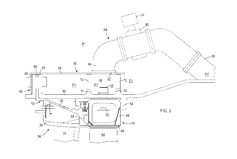
[0021] FIG. 2 is a partially-sectioned view of a turbine section of the
engine of FIG.1;
[0022] FIG. 3 is a top plan view of a portion of a turbine case, showing a
first configuration of
holes in a pair of rings;
[0023] FIG. 4 is a top plan view of a portion of a turbine case, showing a
second configuration
of holes in a pair of rings;
[0024] FIG. 5 is a top plan view of a portion of a turbine case, showing a
third configuration of
holes in a pair of rings;
[0025] FIG. 6 is a front elevational view of a cover shown in FIG. 2; and
[0026] FIG. 7 is a side elevational view of the cover of FIG. 6.
DETAILED DESCRIPTION OF THE INVENTION
[0027] The present invention generally provides a suction-based active
clearance control system
which controls flow using a valve located downstream of an active clearance
control manifold.
[0028] Now, referring to the drawings wherein identical reference numerals
denote the same
elements throughout the various views, FIG. 1 depicts schematically a gas
turbine 10 engine having
a centerline axis "A" and including, among other structures, a fan 12, a low-
pressure compressor or
"booster" 14, a high-pressure compressor ("HPC") 16, a combustor 18, a high-
pressure turbine
("HPT") 20, and a low pressure turbine ("LPT") 22. Collectively the HPC 16,
combustor 18, and
HPT 20 constitute a "core" of the engine 10. The HPC 16 provides compressed
air that passes
primarily into the combustor 18 to support combustion and partially around the
combustor 18 where
it is used to cool both the combustor liners and turbomachinery further
downstream. Fuel is
introduced into the forward end of the combustor 18 and is mixed with the air
in a conventional
fashion. The resulting fuel-air mixture is ignited for generating hot
combustion gases. The hot
CA 02899895 2015-07-30
WO 2014/123654 PCT/US2014/010764
combustion gases are discharged to the HPT 20 where they are expanded so that
energy is extracted.
The HPT 20 drives the high-pressure compressor 16 through an outer shaft 24.
The gases exiting the
HPT 20 are discharged to the low-pressure turbine 22 where they are further
expanded and energy is
extracted to drive the booster 14 and fan 12 through an inner shaft 26. A
portion of the air exiting
the fan 12 bypasses the core, flows through a bypass duct 28, and re-combines
with the exhaust
gases exiting the core at a mixer 30, before exiting through an exhaust nozzle
32.
[0029] In the illustrated example, the engine is a turbofan engine.
However, the principles
described herein are equally applicable to turboprop and turbojet engines, as
well as turbine engines
used for other vehicles or in stationary applications.
[0030] Referring to FIG. 2, The HPT 20 includes a nozzle 34 which comprises
a plurality of
circumferentially spaced airfoil-shaped stationary turbine vanes 36 that are
circumscribed by an
annular outer band 38. The outer band 38 defines the outer radial boundary of
the gas flow through
the turbine nozzle 34. It may be a continuous annular element or it may be
segmented. The turbine
vanes 36 are configured so as to optimally direct the combustion gases to a
downstream rotor.
[0031] Downstream of the nozzle 34, the rotor includes a disk (not shown in
FIG. 2) that rotates
about the centerline axis A and carries an array of airfoil-shaped turbine
blades 40. A shroud
comprising a plurality of arcuate shroud segments 42 is arranged so as to
closely surround the
turbine blades 40 and thereby define the outer radial flowpath boundary for
the hot gas stream
flowing through the rotor.
[0032] In the illustrated example, each shroud segment 42 has a hollow
cross-sectional shape
defined by opposed inner and outer walls, and forward and aft walls.
[0033] The shroud segments 42 may be constructed from a ceramic matrix
composite (CMC)
material of a known type. Generally, commercially available CMC materials
include a ceramic type
fiber for example SiC, forms of which are coated with a compliant material
such as Boron Nitride
(BN). The fibers are carried in a ceramic type matrix, one form of which is
Silicon Carbide (SiC).
Typically, CMC type materials have a room temperature tensile ductility of no
greater than about
1%, herein used to define and mean a low tensile ductility material. Generally
CMC type materials
have a room temperature tensile ductility in the range of about 0.4 to about
0.7%. This is compared
with metals having a room temperature tensile ductility of at least about 5%,
for example in the
range of about 5 to about 15%. The shroud segments 42 could also be
constructed from other low-
CA 02899895 2015-07-30
WO 2014/123654 PCT/US2014/010764
6
ductility, high-temperature-capable materials.
[0034] The shroud segments 42 include opposed end faces 44 (also commonly
referred to as
"slash" faces). Each of the end faces 44 lies in a plane parallel to the
centerline axis A of the engine,
referred to as a "radial plane". They may also be oriented so that the plane
is at an acute angle to
such a radial plane. When assembled and mounted to form an annular ring, end
gaps are present
between the end faces 44 of adjacent shroud segments 42. Accordingly, an array
of seals 46 may be
provided at the end faces 44. Similar seals are generally known as "spline
seals" and take the form
of thin strips of metal or other suitable material which are inserted in slots
in the end faces 44. The
spline seals 46 span the gaps.
[0035] The shroud segments 42 are mounted to a stationary engine structure.
In this example the
stationary structure is an HPT case 48 which is generally a body of revolution
about the centerline
axis A. The HPT case 48 has opposed inner and outer surfaces 49, 51 facing the
interior and exterior
spaces of the HPT case 48, respectively. A hanger 50 or load spreader may be
disposed inside each
of the shroud segments 42. A fastener 52 such as the illustrated bolt engages
the hanger 50, passes
through a mounting hole in the shroud segment 42, and clamps or positions the
shroud segment 42
in the radial direction.
[0036] The turbine case 48 includes a flange 54 which projects radially
inward and defines and
axially-facing bearing surface. This surface acts as a rigid stop to aft
motion of the shroud segments
42.
[0037] A nozzle support 56 is positioned axially forward of the shroud
segment 42. It has a
generally conical body 58. An annular forward flange 60 extends radially
outboard from the forward
end of the body 58. The forward flange 60 is assembled in a bolted joint 62
(or other type of
mechanical joint) to other stationary engine structures which are not the
subject of this invention.
An annular rear flange 64 is disposed at the aft end of the body 56.
[0038] A spring element 66 is disposed between the nozzle support 56 and
the shroud segments
42. When assembled, the spring element 66 loads the shroud segments 42 axially
aft against the
flange 54 of the turbine case 48.
[0039] The forward end of the HPT case 48 includes a radially-extending
forward mounting
flange 68. The forward mounting flange 68 is assembled in the bolted joint 62.
Annular, plate-like
forward and aft rings 70 and 72 extend radially outward from the HPT case 48.
The axial spacing
CA 02899895 2015-07-30
WO 2014/123654 PCT/US2014/010764
7
between the rings 70 and 72 is approximately the same as the axial length of a
shroud segment 42.
[0040] It is noted that, while the present invention is described as
applied to an HPT having a
resiliently-mounted box-type shroud, the principles described here are
applicable to any type of
HPT shroud structure.
[0041] One or both of the rings 70 and 72 include a plurality of holes 74
formed therein,
arranged in an annular array. The holes 74 may extend parallel to the
centerline axis A of the engine
10, or they may be angled in either radial or tangential directions, or both.
As used herein with
respect to the holes 74, the term "angled" indicates that the longitudinal
axes of the holes 74 are
disposed at an acute angle to the centerline axis A when observed in either a
radial plane or a
tangential plane, or both. This could also be described as the holes 74 being
oriented at a non-
parallel, non-perpendicular angle to the centerline axis A in at least one
plane. In FIG. 2, the holes
74 are shown angled in a radial direction. In FIG. 3, the holes 74 in the
forward ring 70 are angled
tangentially, and the holes 74 in the aft ring 72 are angled tangentially but
in opposite direction
(relative to a direction of flow). In FIG. 4, the holes 74 in the forward ring
70 are angled
tangentially, and the holes 74 in the aft ring 72 are angled tangentially but
in the same direction. In
FIG. 5, the holes 74 are shown parallel to the centerline axis A. The size,
spacing, angle, and
position of the holes 74, as well as the shape, dimensions, and positions of
the rings 70 and 72 may
be selected to tailor the thermal performance of the rings 70 and 72 as needed
to suit a specific
application. In addition to directing air flow, the presence of the holes 74
serves to reduce
conductive heat transfer from the HPT case 48 into the rings 70 and 72.
[0042] Referring back to FIG. 2, an annular cover 76 surrounds the rings 70
and 72. The cover
76 includes forward and aft sections. As best seen in FIGS. 6 and 7, the
forward section comprises
an annular array of axially-extending, spaced-apart fingers 78, each finger 78
having a flange 80 at
its distal end. The aft section is cylindrical and includes one or more exit
ports 82 formed therein. In
the illustrated example, there are three exit ports 82 evenly spaced around
the periphery of the cover
76. The flanges 80 are clamped in the bolted joint 62 (FIG. 2) and position
the cover 76 such that
the aft section lies against and surrounds the forward and aft rings 70 and
72. Collectively, the cover
76, the forward and aft rings 70 and 72, and the portion of the HPT case 48
lying between the rings
70 and 72 define an annular manifold "M". It is noted that, in notable
contrast to prior art manifold
structures, no positive attachment, such as a formed, welded, or brazed joint,
is required between the
cover 76 and the rings 70 and 72, as the line contact between the rings 70 and
72 and the cover 76
CA 02899895 2015-07-30
WO 2014/123654 PCT/US2014/010764
8
provides adequate sealing for the purposes of the present invention. The
manifold includes at least
one inlet port for the purpose of admitting airflow therein. In the
illustrated example, the
[0043] The engine 10 is provided with one or more hollow bypass pipes 84.
Each bypass pipe
84 has an upstream end 86 that is coupled to the cover 76. More specifically,
the bore of the bypass
pipe 84 communicates with the port 82 in the cover 76. One bypass pipe 84 is
provided for each port
82. Optionally, the bypass pipes 84 may be positively coupled and/or sealed to
the cover 76, for
example using a welded or brazed joint, or a mechanical connection.
[0044] Each bypass pipe 84 has a downstream end 88 that communicates with a
pressure "sink"
or region of reduced static pressure relative to the region. In the
illustrated example, the downstream
end 88 of each bypass pipe 84 communicates with the turbine rear frame 90 (see
FIG. 1).
[0045] Each bypass pipe 84 incorporates a valve 92 of a known type between
the upstream end
86 and the downstream end 88. The valve 92 is moveable between a closed
position which blocks
flow between the upstream and downstream ends 86 and 88, and an open position
which permits
flow between the upstream and downstream ends 84 and 88. Optionally, the valve
92 may be of a
type which can bet positioned in an intermediate position to modulate flow,
that is, to permit some
amount of flow variable between no flow and maximum flow. The valve 92 may be
operable by
known means such as an electrical, hydraulic, or pneumatic actuator (an
actuator 94 is shown
schematically).
[0046] During engine operation the tip clearance between the turbine blades
40 and the shroud
segments 42 is affected by multiple factors, including (1) rotor elastic
growth, (2) casing pressure
growth, (3) blade thermal growth, (4) casing thermal growth, and (5) rotor
thermal growth. The
sequence and magnitude of these effects collectively determines the actual
clearance at any
particular time.
[0047] During engine acceleration from low-speed conditions, the tip
clearance shrinks, leading
to a minimum clearance, and then increases as time progresses. Such a minimum
is termed a "pinch
point" and places a limit upon the minimum clearance that can be manufactured
into the engine 10.
As a result, clearances at conditions other than the pinch point are more open
than required.
Therefore, to reduce this needlessly large clearance, active clearance control
may be employed to
control the diameter of the turbine case 48 by flowing the relatively cold
bypass air through the
manifold M.
CA 02899895 2015-07-30
WO 2014/123654 PCT/US2014/010764
9
[0048] At all times when the engine is running, the region surrounding the
cover 76 is exposed
to fan bypass flow at a first pressure "P 1 " (this is because the turbine
case 48 is exposed to the
bypass duct 28). This is true even though no special valves, piping, etc. are
used upstream of the
manifold M. The openings in the cover 76 and the holes 74 in the forward and
aft rings 70 and 72
communicate this pressure to the manifold M and to the bore of the bypass
pipes 84 upstream of the
closed valves 92. When the valves 92 are closed, the air stagnates in this
region and no flow takes
place through the bypass pipes 84. The valves 92 would typically be closed
during engine
acceleration, when the highest priority is to avoid blade rubs.
[0049] The downstream ends 88 of the bypass pipes 84 communicate with a
pressure "sink," i.e.,
a region having a prevailing static pressure "P2" which is less than Pl, i.e.,
P1 > P2. When the
valves 92 are open, this pressure difference drives air flow sequentially from
the bypass flowpath,
through the openings in the cover 76 between the fingers 78 (and around the
aft end of the aft ring
72), through the holes 74 in the forward and aft rings 70 and 72, into the
manifold M where it scrubs
the outer surface of the HPT case 48, through the exit ports 82, through the
bypass pipes 84, and
finally out the downstream ends 88 to the pressure sink (e.g. turbine rear
frame 90). This flow may
be dumped overboard or may rejoin an exhaust flowpath of the engine 10. The
valves 92 would
typically be opened during steady-state operating conditions, in order to
minimize the tip clearances.
This type of control, wherein the valves 92 are positioned downstream of the
manifold M, may be
referred to as "suction-based" active clearance control.
[0050] Operation of the clearance valves 92 to control flow through the
manifold M, and thus
clearance may be carried out using known apparatus and methods. For example,
the engine 10 may
be provided with one or more temperature and/or clearance measurement sensors
(not shown). Input
from such sensors may be provided to an electronic controller which uses known
algorithms to
determine whether the valves 92 should be closed, partially open, or fully
open during each phase of
engine operation.
[0051] The active clearance control apparatus and method described herein
has several
advantages over prior art systems. It uses fan bypass air as a cooling fluid.
This bypass flow is
available for use without the need for complex, expensive valves and piping
upstream of the point of
use. Furthermore, the manifold structure is much simpler than prior art
systems using separate
fabricated manifolds for active clearance control.
[0052] The foregoing has described a clearance control structure and method
for a gas turbine
CA 02899895 2015-07-30
WO 2014/123654 PCT/US2014/010764
engine. All of the features disclosed in this specification (including any
accompanying claims,
abstract and drawings), and/or all of the steps of any method or process so
disclosed, may be
combined in any combination, except combinations where at least some of such
features and/or
steps are mutually exclusive.
[0053] Each feature disclosed in this specification (including any
accompanying claims, abstract
and drawings) may be replaced by alternative features serving the same,
equivalent or similar
purpose, unless expressly stated otherwise. Thus, unless expressly stated
otherwise, each feature
disclosed is one example only of a generic series of equivalent or similar
features.
[0054] The invention is not restricted to the details of the foregoing
embodiment(s). The
invention extends any novel one, or any novel combination, of the features
disclosed in this
specification (including any accompanying claims, abstract and drawings), or
to any novel one, or
any novel combination, of the steps of any method or process so disclosed.