Note: Descriptions are shown in the official language in which they were submitted.
I I
=
CA 2900459 2017-04-06
DESCRIPTION
TITLE OF THE INVENTION: FUEL CELL PROVIDING UNIFORM FUEL GAS
PRESSURE DISTRIBUTION IN A POWER GENERATION
REGION
[0001] TECHNICAL FIELD
[0002]
The present invention relates to a fuel cell.
BACKGROUND ART
[0003]
There has been known a solid oxide fuel cell employing
a solid electrolyte (solid oxide) (hereinafter the battery
may be referred to as an "SOFC"). Such an SOFC employs a
single cell which is formed of a solid electrolyte layer, an
anode provided on one surface of the electrolyte layer, and a
cathode provided on the other surface of the electrolyte
layer. A fuel gas (e.g., hydrogen) and an oxidant gas are
supplied to the anode and the cathode, respectively, and
these gases are caused to react with each other, whereby the
single cell generates electric power.
[0004]
1
CA 02900459 2015-08-06
There has been disclosed a technique for supplying a
fuel gas uniformly so as to achieve reliable electric power
generation (see Patent Document 1). In this technique, an
inlet buffer portion is provided on the upstream side of a
fuel gas path, and a fuel gas inlet communication hole and
the inlet buffer portion are connected by means of a
plurality of inlet communication paths.
PRIOR ART DOCUMENT
PATENT DOCUMENT
[0005]
Patent Document 1: Japanese Patent Application Laid-Open
(kokai) No. 2011-051404
SUMMARY OF THE INVENTION
PROBLEMS TO BE SOLVED BY THE INVENTION
[0006]
However, the technique described in Patent Document 1
is not necessarily satisfactory in terms of uniform power
generation efficiency. Specifically, the pressure at the gas
inlet port of the inlet buffer portion is higher than that at
a position away from the inlet port; i.e., pressure
distribution is not uniform. Non-uniform pressure
distribution may cause non-uniform gas diffusion in a power
generation region, resulting in non-uniform power generation
efficiency. Therefore, in-plane temperature distribution may
become non-uniform in the single cell, resulting in damage
2
CA 02900459 2015-08-06
to, for example, the single cell due to thermal stress.
An object of the present invention is to provide a fuel
cell which readily achieves uniform fuel gas pressure
distribution, and realizes uniform gas diffusion in a power
generation region.
MEANS FOR SOLVING THE PROBLEMS
[0007]
(1) One mode of the present invention is a fuel cell
comprising a plate-like interconnector having a front surface
and a back surface; a single cell having a power generation
function; a gas chamber provided between the interconnector
and the single cell; and one or more gas inlet ports for
causing a fuel gas to flow into the gas chamber, the fuel
cell further comprising a buffer chamber provided between the
gas inlet port(s) and the gas chamber; a flow direction
changing portion provided between the buffer chamber and the
gas chamber so as to be located at a position corresponding
to the gas inlet port(s), the flow direction changing portion
having at least one of a front surface and a back surface,
and a side surface; and a fuel gas path provided on at least
one of the front surface side and the back surface side of
the flow direction changing portion.
[0008]
The fuel battery has the flow direction changing
portion, which is provided between the buffer chamber and the
gas chamber so as to be located at a position corresponding
3
CA 02900459 2015-08-06
to the gas inlet port(s).
The flow direction changing portion changes the flow
direction of a fuel gas flowing through the gas inlet ports,
and the fuel gas flows into the gas chamber.
[0009]
The fuel cell is configured so that a portion of the
fuel gas flowing through the gas inlet ports into the buffer
chamber is blocked by the side surface of the flow direction
changing portion, and then flows into the gas chamber along
the fuel gas path provided on at least one of the front
surface and the back surface of the flow direction changing
portion.
Therefore, uniform fuel gas pressure distribution can
be achieved in the buffer chamber, and uniform gas diffusion
can be attained in a power generation region.
[0010]
(2) The flow direction changing portion may have one
side surface which faces the gas inlet ports.
[0011]
When the flow direction changing portion has one side
surface which faces the gas inlet ports, pressure loss can be
increased, and thus a buffering effect (i.e., uniform
distribution of the gas flowing through the gas inlet ports)
is improved.
In contrast, for example, in the fuel cell described in
Patent Document 1, which includes an inlet buffer portion
having a plurality of embossments (see paragraph 0030),
4
CA 02900459 2015-08-06
satisfactory buffering effect is difficult to attain, since
the separated embossments do not have one side surface which
faces a plurality of gas inlet ports.
[0012]
(3) The one side surface may be generally perpendicular
to the flow direction of a fuel gas flowing through the gas
inlet ports.
[0013]
When the one side surface is generally perpendicular to
the flow direction of the fuel gas, pressure loss can be
further increased, and thus a buffering effect (i.e., uniform
distribution of the gas flowing through the gas inlet ports)
is improved.
[0014]
(4) The fuel cell may further comprise a current
collector which is provided in the gas chamber and which is
electrically connected to the interconnector and the single
cell, wherein the gas inlet ports, the flow direction
changing portion, and the current collector may be arranged
substantially in a common plane.
[0015]
When the gas inlet ports and the flow direction
changing portion are arranged substantially in a common
plane, pressure loss can be further increased, and thus a
buffering effect (i.e., uniform distribution of the gas
flowing through the gas inlet ports) is improved.
Meanwhile, when the gas inlet ports, the flow direction
CA 02900459 2015-08-06
changing portion, and the current collector are arranged
substantially in a common plane, the thickness of the fuel
cell is readily reduced.
[0016]
(5) The flow direction changing portion may be
integrated with the current collector.
[0017]
When the flow direction changing portion is integrated
with the current collector, the number of components forming
the fuel cell is reduced, and the size of the fuel cell is
readily reduced.
[0018]
(6) The current collector may comprise a first
electrically conductive member, a spacer provided on the
first electrically conductive member, and a second
electrically conductive member provided on the spacer and
electrically connected to the first electrically conductive
member. The flow direction changing portion may be
integrated with the spacer.
[0019]
When the flow direction changing portion is integrated
with the spacer, the number of components forming the fuel
cell is reduced, and the size of the fuel cell is readily
reduced.
Particularly, when the spacer itself functions as the
flow direction changing portion, the number of components can
be more effectively reduced.
6
CA 02900459 2015-08-06
[0020]
(7) The fuel cell may comprise a frame-shaped portion,
and the frame-shaped portion may have thereon the gas inlet
ports.
[0021]
When the frame-shaped portion having a plurality of the
gas inlet ports is employed, the number of components forming
the fuel cell is reduced, and the size of the fuel cell is
readily reduced.
[0022]
At least a portion of the frame-shaped portion may be
formed of a metal.
When at least a portion of the frame-shaped portion is
formed of a metal, a plurality of gas inlet ports are formed
in the frame-shaped portion with improved processing
accuracy, and the pressure distribution of a fuel gas flowing
into the gas chamber is made more uniform, as compared with
the case where the frame-shaped portion is formed of an
insulation material such as mica.
[0023]
(8) The flow direction changing portion may be
integrated with the interconnector.
[0024]
When the flow direction changing portion is integrated
with the interconnector, the number of components forming the
fuel cell is reduced, and the size of the fuel cell is
readily reduced. In addition, a gap is readily provided in
7
CA 02900459 2015-08-06
the single cell, and a fuel gas is readily supplied uniformly
into the single cell.
EFFECTS OF THE INVENTION
[0025]
According to the present invention, there can be
provided a fuel cell which readily realizes a reduction in
contact resistance, and a method for producing the fuel cell.
BRIEF DESCRIPTION OF THE DRAWINGS
[0026]
[FIG. 1]
FIG. 1 is a perspective view of a fuel cell stack 100
according to a first embodiment.
[FIG. 2]
FIG. 2 is a perspective view of a cell unit 103 of the
fuel cell stack 100.
[FIG. 3]
FIG. 3 is an exploded perspective view of the cell unit
103 of the fuel cell stack 100.
[FIG. 4]
FIG. 4 is a cross-sectional view of the cell unit 103
of the fuel cell stack 100.
[FIG. 5]
FIG. 5 is a perspective view of a current collector
119.
[FIG. 6]
8
CA 02900459 2015-08-06
FIG. 6 is an exploded perspective view of the current
collector 119.
[FIG. 7]
FIG. 7 is a schematic cross-sectional view of the cell
unit 103 of the fuel cell stack 100.
[FIG. 8]
FIG. 8 is a schematic cross-sectional view of a cell
unit 103a of a fuel cell stack 100a according to a second
embodiment.
[FIG. 9]
FIG. 9 is a perspective view of a current collector 219
according to modification 1.
[FIG. 10]
FIG. 10 is an enlarged perspective view of the current
collector 219 according to modification 1.
[FIG. 11]
FIG. 11 is a perspective view of a flat metal member
290 according to modification 1.
[FIG. 12]
FIG. 12 is a perspective view of a flat insulation
member 250 according to modification 1.
[FIG. 13]
FIG. 13 is a schematic representation of a cell unit
103b according to modification 2.
[FIG. 14]
FIG. 14 is a schematic representation of a cell unit
103c according to modification 3.
9
CA 02900459 2015-08-06
[FIG. 15]
FIG. 15 is a schematic representation of a cell unit
103d according to modification 4.
[FIG. 16]
FIG. 16 is a schematic representation of a cell unit
103e according to modification 5.
[FIG. 17]
FIG. 17 is a cross-sectional view showing the
relationship between the height HO of a fuel chamber 117 and
the thickness H1 of a flow direction changing portion 161.
[FIG. 18]
FIG. 18 is a graph showing the relationship between
height ratio R and in-plane flow distribution error E.
MODES FOR CARRYING OUT THE INVENTION
[0027]
Embodiments of the present invention will next be
described in detail with reference to the drawings.
(First embodiment)
FIG. 1 is a perspective view of a fuel cell stack (fuel
cell) 100 according to a first embodiment. The fuel cell
stack 100 includes cell units 103, an air supply path 104, an
air discharge path 105, a fuel supply path 106, a fuel
discharge path 107, and fixing members 109.
[0028]
FIGs. 2 to 4 are respectively a perspective view, an
exploded perspective view, and a cross-sectional view of each
CA 02900459 2015-08-06
cell unit 103.
Each cell unit 103 serves as a minimum unit for power
generation, and includes interconnectors 112 and 113, a
single cell 120, an air chamber 116, a fuel chamber (gas
chamber) 117, and current collectors 118 and 119.
[0029]
The interconnectors 112 and 113 are in quadrangular
plate form in plan view, and are formed of, for example,
electrically conductive ferrite stainless steel. The
interconnectors 112 and 113 are arranged in a vertical
direction.
[0030]
(Single cell 120)
The single cell 120 is located generally at the middle
between the interconnectors 112 and 113, and has an
electrolyte 102, a cathode 114, and an anode 115. The
cathode 114 and the anode 115 are respectively provided on
the upper and lower surfaces of the electrolyte 102.
[0031]
The electrolyte 102 may be formed of, for example, a
Zr02 ceramic material, an LaGa03 ceramic material, a BaCe03
ceramic material, an SrCe03 ceramic material, an SrZr03
ceramic material, or a CaZr03 ceramic material.
[0032]
The anode 115 may be formed of a mixture of a metal
such as Ni or Fe, and at least one species selected from
among ceramic materials such as Ce02 ceramic materials and
11
CA 02900459 2015-08-06
Zr02 ceramic materials (e.g., zirconia stabilized by at least
one species selected from among rare earth elements such as
Sc and Y). The anode 115 may be formed of a metal such as
Pt, Au, Ag, Pb, Ir, Ru, Rh, Ni, or Fe. The anode 115 may be
formed of only one species of these metals, or an alloy of
two or more species of the metals. Alternatively, the anode
115 may be formed of a mixture of such a metal and/or an
alloy thereof and at least one species of the aforementioned
ceramic materials (the mixture including cermet).
Alternatively, the anode 115 may be formed of, for example, a
mixture an oxide of a metal such as Ni or Fe, and at least
one species of the aforementioned ceramic materials.
[0033]
The cathode 114 may be formed of, for example, any
metal, any metal oxide, or any metal multiple oxide.
Examples of the metal include metals such as Pt, Au, Ag, Pb,
It, Ru, and Rh; and alloys containing two or more of these
metals. Examples of the metal oxide include oxides of La,
Sr, Ce, Co, Mn, Fe, and the like (e.g., La203, Sr0, Ce203,
Co20i, Mn02, and FeO) . Examples of the multiple oxide include
multiple oxides containing, for example, at least La, Pr, Sm,
Sr, Pa, Co, Fe, or Mn (e.g., La15SrxCo03 multiple oxides, La1-
xSrxFe02 multiple oxides, La1,SrxCo1_yFe02 multiple oxides, La1-
.Sr8Mn03 multiple oxides, PriõBaxCo03 multiple oxides, and Smi_
xSrõCo03 multiple oxides).
12
CA 02900459 2015-08-06
[0034]
(Air chamber 116)
The air chamber 116 is provided between the
interconnector 112 and the cathode 114, and is a space into
which an oxidant gas is supplied. The air chamber 116 is
defined by a separator 123, a cathode insulation frame 124,
and the interconnector 112.
[0035]
The separator 123 is an electrically conductive, thin
metallic quadrangular frame-like portion, and the electrolyte
102 is attached to the lower surface of the separator 123.
The cathode insulation frame 124 is provided between
the separator 123 and the upper interconnector 112, and
surrounds the current collector 118.
[0036]
(Fuel chamber (gas chamber) 117)
The fuel chamber 117 is provided between the
interconnector 113 and the anode 115, and is a space into
which a fuel gas is supplied. The fuel chamber 117 is
defined by combination of the interconnector 113, an anode
insulation frame 121, and an anode frame 122.
[0037]
The anode insulation frame 121 surrounds the current
collector 119, and is provided on the lower surface of the
lower interconnector 113.
[0038]
The anode frame 122 is provided on the upper surface of
13
CA 02900459 2015-08-06
the anode insulation frame 121.
[0039]
(Buffer chamber 160)
As shown in FIGs. 2 to 4, a buffer chamber 160 is
provided between a fuel supply communication portion 140 and
the current collector 119 (and the fuel chamber 117). That
is, the buffer chamber 160 is a space which is defined by the
interconnector 113, the anode insulation frame 121, and the
anode frame 122, and in which the current collector 119 (and
the anode 115) on the side toward the fuel supply
communication portion (gas inlet port) 140 are not provided.
The buffer chamber 160 is a space into which a fuel gas
supplied through the fuel supply communication portion 140
flows. Since the fuel gas supplied through the fuel supply
communication portion 140 diffuses in the buffer chamber 160,
the fuel gas flows uniformly in the fuel chamber 117.
[0040]
(Current collector 118)
The current collector 118 is a connection member which
is provided within the air chamber 116, and which
electrically connects the cathode 114 to the upper
interconnector 112.
[0041]
The current collector 118 on the side toward the air
chamber 116 is formed of, for example, a dense electrically
conductive member having an elongated squared timber shape
(e.g., a stainless steel material). A plurality of current
14
CA 02900459 2015-08-06
collectors 118 are arranged in parallel at certain intervals
so as to abut the cathode 114 on the upper surface of the
electrolyte 102 and the lower surface (inner surface) of the
upper interconnector 112. The current collector 118 on the
side toward the air chamber 116 may have the same structure
as the current collector 119 on the side toward the fuel
chamber 117.
[0042]
(Current collector 119)
The current collector 119 is a connection member which
is provided within the fuel chamber 117, and which
electrically connects the fuel chamber 117 to the lower
interconnector 113.
[0043]
FIGs. 5 and 6 are respectively a perspective view and
an exploded perspective view of the current collector 119.
The current collector 119 is formed of combination of a
flat metal member 190 and a flat insulation member 150. The
current collector 119 can be formed by stacking the flat
metal member 190 and the flat insulation member 150 together,
and folding the flat metal member 190.
[0044]
The flat metal member 190 is formed of, for example, an
Ni plate material, and has a connector abutment portion
(electrically conductive member) 119a, a single cell abutment
portion (electrically conductive member) 119b, a
communication portion 119c, and a connection portion 119d,
CA 02900459 2015-08-06
which will be described hereinbelow. A plurality of units
each including the connector abutment portion 119a, the
single cell abutment portion 119b, and the communication
portion 119c are connected together by means of the
connection portions 119d.
[0045]
The flat insulation member 150 is formed of a material
which is not sintered to the flat metal member 190 at the
operating temperature region of the fuel cell. The material
of the flat insulation member 150 may be any of mica,
alumina, vermiculite, carbon fiber, silicon carbide fiber,
and silica, or may contain at least one species of these as a
main component. Preferably, the flat insulation member 150
is formed of a stacking structure of thin plates (e.g.,
mica), since appropriate elasticity is imparted with respect
to a load in a stacking direction.
The flat insulation member 150 has a spacer 158 and a
flow direction changing portion 161, which will be described
hereinbelow.
[0046]
The current collector 119 has the connector abutment
portion (electrically conductive member) 119a, the single
cell abutment portion (electrically conductive member) 119b,
the communication portion 119c, the spacer 158, and the flow
direction changing portion 161.
[0047]
The connector abutment portion (electrically conductive
16
CA 02900459 2015-08-06
member) 119a abuts the interconnector 113, and the single
cell abutment portion (electrically conductive member) 119b
abuts the anode 115 of the single cell 120.
The communication portion 119c is a U-shaped member
which connects the connector abutment portion 119a and the
single cell abutment portion 119b.
[0048]
The current collector 119 may be formed of, in place of
a plate material, for example, porous Ni, Ni mesh, or Ni
wire. Alternatively, the current collector 119 may be formed
of, in place of Ni, an oxidation-resistant metal such as an
Ni alloy or stainless steel.
[0049]
In the fuel chamber 117 between the single cell 120 and
the lower interconnector 113, the spacer 158 is provided
between the connector abutment portion 119a and the single
cell abutment portion 119b.
[0050]
The flow direction changing portion 161 of the flat
insulation member 150 is connected to the spacer 158, and
projects from the current collector 119. The flow direction
changing portion 161 changes the flow direction of a fuel gas
flowing from the buffer chamber 160 into the fuel chamber
117, whereby the fuel gas flows uniformly in the fuel chamber
117. This phenomenon will be described in detail below.
[0051]
Each cell unit 103 also includes an air supply unit
17
CA 02900459 2015-08-06
125, an air discharge unit 126, a fuel supply unit 127, and a
fuel discharge unit 128.
[0052]
(Air supply unit 125)
The air supply unit 125 includes an air supply through
hole 129, an air supply communication chamber 130, a
partition wall 131, an air supply communication portion 132,
and the air supply path 104.
The air supply through hole 129 is provided so as to
extend in a vertical direction at the center of one side of
the quadrangular cell unit 103.
The air supply communication chamber 130 is an
elongated-hole-shaped space which is provided in the cathode
insulation frame 124 so as to communicate with the air supply
through hole 129.
The partition wall 131 is provided between the air
supply communication chamber 130 and the air chamber 116.
The air supply communication portion 132 is formed of a
plurality of dents provided at regular intervals on the upper
surface of the partition wall 131.
The air supply path 104 is inserted in the air supply
through hole 129 for supplying air from the outside into the
air supply communication chamber 130.
[0053]
(Air discharge unit 126)
The air discharge unit 126 includes an air discharge
through hole 133, an air discharge communication chamber 134,
18
CA 02900459 2015-08-06
an air discharge communication portion 136, and the air
discharge path 105.
The air discharge through hole 133 is provided so as to
extend in a vertical direction at the center of the side of
the cell unit 103 opposite the air supply unit 125.
The air discharge communication portion 136 is an
elongated-hole-shaped space which is provided in the cathode
insulation frame 124 so as to communicate with the air
discharge through hole 133.
The air discharge communicating portion 136 is formed
of a plurality of dents provided at regular intervals on the
upper surface of a partition wall 135 between the air
discharge communication chamber 134 and the air chamber 116.
The air discharge path 105 is a tubular path which is
inserted in the air discharge through hole 133 for
discharging air from the air discharge communication chamber
134 to the outside.
[0054]
(Fuel supply unit 127)
The fuel supply unit 127 includes a fuel supply through
hole 137, a fuel supply communication chamber 138, a fuel
supply communication portion (gas inlet port) 140, and the
fuel supply path 106.
[0055]
The fuel supply through hole 137 is provided so as to
extend in a vertical direction at the center of one of the
remaining two sides of the quadrangular cell unit 103.
19
CA 02900459 2015-08-06
The fuel supply communication chamber 138 is an
elongated-hole-shaped space which is provided in the anode
insulation frame 121 so as to communicate with the fuel
supply through hole 137.
The fuel supply communication portion (gas inlet port)
140 is formed of a plurality of dents provided at regular
=intervals on the upper surface of a partition wall 139
between the fuel supply communication chamber 138 and the
buffer chamber 160.
The fuel supply path 106 is a tubular path which is
inserted in the fuel supply through hole 137 for supplying a
fuel gas from the outside into the fuel supply communication
chamber 138.
[0056]
(Fuel discharge unit 128)
The fuel discharge unit 128 includes the fuel discharge
path 107 for discharging a fuel gas from the fuel chamber 117
to the outside.
[0057]
The fuel discharge unit 128 includes a fuel discharge
through hole 141, a fuel discharge communication chamber 142,
a partition wall 143, a fuel discharge communication portion
144, and the fuel discharge path 107.
The fuel discharge through hole 141 is provided so as
to extend in a vertical direction at the center of the side
of the cell unit 103 opposite the fuel supply unit 127.
The fuel discharge communication chamber 142 is an
CA 02900459 2015-08-06
elongated-hole-shaped space which is provided in the anode
insulation frame 121 so as to communicate with the fuel
discharge through hole 141.
The partition wall 143 is provided between the fuel
discharge communication chamber 142 and the fuel chamber 117.
The fuel discharge communication portion 144 is formed
of a plurality of dents provided at regular intervals on the
upper surface of the partition wall 143.
The fuel discharge path 107 is inserted in the fuel
discharge through hole 141 for discharging the fuel gas from
the fuel discharge communication chamber 142 to the outside.
[0058]
(Fixing member 109)
The fuel cell stack 100 is produced by fixing, by means
of the fixing members 109, a cell group prepared through
stacking of a plurality of the aforementioned cell units 103.
When a plurality of the cell units 103 are stacked
together, the upper interconnector 112 of the cell unit 103
located on the lower side is integrated with the lower
interconnector 113 of the cell unit 103 located on the lower-
side cell unit 103, and the thus-integrated interconnector is
shared by the upper and lower cell units 103, 103.
[0059]
The fixing members 109 are a combination of a pair of
end plates 145a and 145b and four clamping members 146a to
146d.
The paired end plates 145a and 145b vertically sandwich
21
CA 02900459 2015-08-06
the cell group.
Each of the clamping members 146a to 146d for clamping
the end plates 145a and 145b and the cell group includes a
clamping nut and a bolt penetrating corner holes (not
illustrated) of the end plates 145a and 145b and the
aforementioned corner holes 147 of the cell group. The
clamping members 146a to 146d are formed of, for example,
Inconel 601.
[0060]
The air supply path 104 is attached to the fuel cell
stack 100 so as to vertically penetrate the through holes
(not illustrated) of the end plates 145a and 145b and the air
supply through holes 129 of the cell group.
[0061]
(Achievement of uniform fuel gas pressure distribution in
buffer chamber)
In the present embodiment, the buffer chamber 160 and
the flow direction changing portion 161 are provided between
the fuel supply communication portion 140 and the fuel
chamber 117. Therefore, pressure distribution becomes
uniform in the buffer chamber 160, and the fuel gas flows
uniformly in the fuel chamber 117. This phenomenon will now
be described in detail.
[0062]
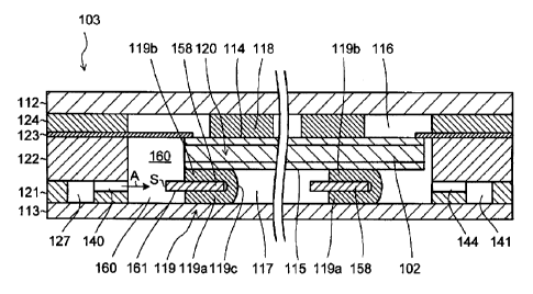
FIG. 7 is a schematic cross-sectional view of the cell
unit 103. FIG. 7(A) is a cross-sectional view of the cell
unit of FIG. 5 taken along line A-A, and FIG. 7(B) is a
22
CA 02900459 2015-08-06
cross-sectional view of the cell unit of FIG. 5 taken along
line B-B.
The cell unit 103 has regions Rl to R4, which are
determined according to the flow of a fuel gas. The regions
R1 to R4 respectively correspond to the locations of the fuel
supply communication portion (gas inlet port) 140, the buffer
chamber 160, the flow direction changing portion 161, and the
fuel chamber (gas chamber) 117.
[0063]
Since a fuel gas flows into the buffer chamber 160
through a plurality of the fuel supply communication portions
(gas inlet ports) 140 and diffuses in the buffer chamber 160,
uniform pressure distribution is achieved in the buffer
chamber 160, and the fuel gas flows uniformly in the fuel
chamber 117.
[0064]
The flow direction changing portion 161 is provided
between the buffer chamber 160 and the fuel chamber 117 so as
to correspond to a plurality of the fuel supply communication
portions 140. The flow direction changing portion 161
changes the flow direction F of a fuel gas flowing into the
buffer chamber 160 through a plurality of the fuel supply
communication portions 140. Therefore, uniform pressure
distribution can be achieved in the buffer chamber 160, and
the fuel gas can flow uniformly in the fuel chamber 117.
[0065]
As shown in FIGs. 7(A) and 7(B), even when a fuel gas
23
CA 02900459 2015-08-06
flows through the current collector 119 in the flow direction
F along any of lines A-A and B-B shown in FIG. 5, uniform
pressure distribution can be achieved by means of the flow
direction changing portion 161.
[0066]
Specifically, the flow direction changing portion 161
has one side surface S facing a plurality of the fuel supply
communication portions 140. A fuel gas flowing through the
fuel supply communication portions 140 collides with the side
surface S, and thus the flow direction of the fuel gas
changes. When the fuel gas collides with the side surface S,
pressure loss occurs, and uniform pressure distribution is
achieved. When the side surface S is provided so as to face
all the fuel supply communication portions 140, pressure loss
can be increased, and further uniform pressure distribution
can be achieved.
[0067]
The side surface S is generally perpendicular to the
flow direction F of a fuel gas flowing through a plurality of
the fuel supply communication portions 140. The side surface
S may be inclined with respect to the flow direction F.
However, when the side surface S is generally perpendicular
to the flow direction F, pressure loss is further increased,
and further uniform pressure distribution is achieved.
[0068]
In the present embodiment, a plurality of the fuel
supply communication portions 140 and the flow direction
24
CA 02900459 2015-08-06
changing portion 161 are arranged substantially in a common
plane. Therefore, pressure loss is further increased, and
further uniform pressure distribution is achieved.
[0069]
In the present embodiment, the in-line spacers 158 are
arranged in an irregular pattern in plan view. As shown in
FIG. 6, gaps are provided between a plurality of the spacers
158 which are in-line connected by means of the flow
direction changing portion 161. That is, the downstream-side
ends of the in-line spacers 158 are discontinuous.
The case where the downstream-side ends of the in-line
spacers 158 are continuous will be described below in
modification 1.
[0070]
In the present embodiment, each cell unit 103 includes
a plurality of the fuel supply communication portions (gas
inlet ports) 140 (and a plurality of the fuel discharge
communication portions (gas outlet ports) 144). The case
where each cell unit 103 includes a single fuel supply
communication portion (gas inlet port) 140 (or a single fuel
discharge communication portion (gas outlet port) 144) will
be described below in modifications 2 to 5.
[0071]
(Second embodiment)
A second embodiment will next be described.
FIG. 8 corresponds to FIG. 4 showing the first
embodiment, and is a schematic cross-sectional view of a cell
CA 02900459 2015-08-06
unit 103a of a fuel cell stack 100 according to the second
embodiment.
[0072]
Unlike the case of the first embodiment, in the cell
unit 103a, a current collector 119 does not have a flow
direction changing portion 161. A flow direction changing
portion 161a is attached to an interconnector 113 or
integrated with the interconnector 113.
The flow direction changing portion 161a has a
thickness larger than that of the flow direction changing
portion 161 of the first embodiment, and the side surface Sa
of the flow direction changing portion 161 has a larger area.
Therefore, and a fuel gas more reliably collides with the
side surface Sa, pressure loss is further increased. Thus,
further uniform pressure distribution is achieved.
Although a gap is provided between the current
collector 119 and the flow direction changing portion 161a,
this gap may be omitted.
[0073]
Modifications 1 to 5 of the present invention will next
be described.
In each of modifications 1 to 5, components of a fuel
cell stack have the same configurations as those of the fuel
cells of the aforementioned embodiments, and thus detailed
description thereof is omitted. Specifically, the fuel cell
stack has the same configuration as that shown in, for
example, FIGs. 1 to 4, except for modified portions.
26
CA 02900459 2015-08-06
[0074]
(Modification 1)
FIGs. 9 to 12 show, for example, a current collector
219 of a fuel cell stack according to modification 1. In
this fuel cell stack, as shown in FIG. 12, the downstream-
side ends of in-line spacers 258 are continuous.
[0075]
The current collector 219 includes a flat metal member
290 and a flat insulation member 250.
[0076]
The flat metal member 290 is formed by, for example,
providing pre-cut lines 219e in an Ni plate material (HV
hardness: 200 or less) which has been subjected to thermal
treatment (annealing) under vacuum at 1,000 C for one hour.
Annealing may he preceded or followed by cutting.
[0077]
Similar to the case shown in FIG. 4, the flat metal
member 290 (or the current collector 219) has a connector
abutment portion 219a which abuts an interconnector 113, a
single cell abutment portion 219h which abuts an anode 115 of
a cell main body 120, and a U-shaped communication portion
219c which connects the connector abutment portion 219a and
the single cell abutment portion 219b, the portions 219a to
219c being continuously formed. By means of the elastic
force of the U-shaped communication portion 219c, the
connector abutment portion 219a and the single cell abutment
portion 219b are respectively biased toward the
27
CA 02900459 2015-08-06
interconnector 113 and the cell main body 120.
[0078]
Since the connector abutment portion 219a is located
opposite the single cell abutment portion 219b, reference
numeral 219a is not shown in FIG. 10.
[0079]
The current collector 219 may be formed of, in place of
the aforementioned plate material, for example, porous Ni, Ni
mesh, or Ni wire. Alternatively, the current collector 219
may be formed of, in place of Ni, an oxidation-resistant
metal such as an Ni alloy or stainless steel.
[0080]
About several tens to one hundred current collectors
219 are provided in a fuel chamber 117 (the number of the
current collectors may vary in association with the size of
the fuel chamber).
[0081]
As shown in FIG. 12, the flat insulation member 250 has
a spacer 258, a flow direction changing portion 261, and a
spacer connection portion 259, which are integrally formed.
[0082]
The spacer 258 is provided between the connector
abutment portion 219a and the single cell abutment portion
219b, and exhibits elastic force in a thickness direction.
As shown in FIG. 6, the downstream-side ends of the in-line
spacers 158 are discontinuous. In contrast, as shown in FIG.
12, the downstream-side ends of the in-line spacers 258 are
28
CA 02900459 2015-08-06
continuous and form a straight line.
[0083]
The flow direction changing portion 261 of the flat
insulation member 250 projects between the connector abutment
portion 219a and the single cell abutment portion 219b.
Similar to the case of the flow direction changing portion
161, the flow direction changing portion 261 changes the flow
direction of a fuel gas flowing from a buffer chamber 160
into the fuel chamber 117, whereby the fuel gas flows
uniformly in the fuel chamber 117.
[0084]
The spacer connection portions 259 forming the flat
insulation member 250 connect a plurality of the spacers 258
together.
[0085]
From the viewpoint of preventing bonding between the
connector abutment portion 219a and the single cell abutment
portion 219b, the material of the flat insulation member 250
may be any one species or a combination of a plurality of
species selected from among mica, alumina felt, vermiculite,
carbon fiber, silicon carbide fiber, and silica. When the
flat insulation member 250 is formed of a stacking structure
of thin plates (e.g., mica), appropriate elasticity can be
secured with respect to a load in a stacking direction.
[0086]
(Modifications 2 to 5)
FIGs. 13 to 16 schematically show fuel cells (cell
29
CA 02900459 2015-08-06
units 103b to 103e) according to modifications 2 to 5 of the
present invention, respectively. Each of the cell units 103b
to 103e of modifications 2 to 5 includes a single fuel supply
communication portion (gas inlet port) 140 (or a single fuel
discharge communication portion (gas outlet port) 144).
[0087]
Each of the cell units 103b and 103c shown in FIGs. 13
and 14 includes a single fuel supply communication portion
(gas inlet port) 140.
[0088]
Meanwhile, each of the cell units 103d and 103e shown
in FIGs. 15 and 16 includes a single fuel discharge through
hole (gas outlet port) 141.
[0089]
Thus, even when a plurality of the fuel supply
communication portions (gas inlet ports) 140 (or a plurality
of the fuel discharge through holes (gas outlet ports) 141)
are not provided, the flow direction changing portion 261
changes the flow direction of a fuel gas flowing from the
buffer chamber 160 into the fuel chamber 117, whereby the
fuel gas can flow uniformly in the fuel chamber 117.
[0090]
In these modifications, the current collector 219
(having the flow direction changing portion 261) is employed
in the fuel chamber 117. However, the current collector 119
(having the flow direction changing portion 161) may be
employed in the fuel chamber 117.
CA 02900459 2015-08-06
[0091]
(Other embodiments)
Embodiments of the present invention are not limited to
those described above and may be expanded and modified. The
thus-expanded and modified embodiments are also included in
the technical scope of the present invention.
[0092]
In the aforementioned embodiments, the fuel supply
communication portion (gas inlet port) 140 is provided on the
anode insulation frame 121 (insulative frame member).
However, the fuel supply communication portion (gas inlet
port) 140 may be provided on the anode frame (electrically
conductive (metallic) frame member).
[0093]
(Experimental example)
An experimental example of the present invention will
next be described. As described above, an object of the
present invention is to achieve uniform gas diffusion in a
power generation region. In the present experimental
example, there was determined the relationship between height
ratio R and in-plane flow distribution error E.
As used herein, "height ratio R" refers to the ratio of
the thickness H1 of the flow direction changing portion 161
(i.e., the height of one side surface S facing the fuel
supply communication portions 140) to the height HO of the
fuel chamber 117; i.e., R = (H1/H0). As shown in FIG. 17,
the current collector 119 (the connector abutment portion
31
CA 02900459 2015-08-06
119a and the single cell abutment portion 119b) and the flow
direction changing portion 161 (integrated with the spacer
158) are provided in the fuel chamber 117. There may be the
case where a gap SP (not illustrated) is present between the
single cell abutment portion 119b and the spacer 158.
[0094]
The aforementioned thicknesses satisfy the following
relations:
HO - H1 + H21 + H22 + H3
= H1 + H2 + H3
HO: height of the fuel chamber 117;
Hl: thickness of the flow direction changing portion
161 (height of the side surface S facing the fuel supply
communication portions 140);
H21: thickness of the connector abutment portion 119a;
H22: thickness of the single cell abutment portion
119b;
H2 (= H21 + H22): thickness of the current collector
119; and
H3: thickness of the gap SP.
[0095]
In the present experimental example, the flow path
height HO was adjusted to 1.2 mm, the current collector
height H2 was adjusted to 0.7 mm, and the thickness H1 of the
flow direction changing portion 161 was varied to 0 mm, 0.25
mm, or 0.5 mm. In this case, the thickness H3 of the gap SP
(not illustrated) becomes 0.5 mm, 0.25 mm, or 0 mm, and the
32
CA 02900459 2015-08-06
height ratio R becomes 0, 0.21, or 0.42.
[0096]
As used herein, "in-plane flow distribution error E"
refers to a variation in flow rate at a position immediately
upstream of the flow direction changing portion 161
(specifically, at a position 0.5 mm upstream of the flow
direction changing portion 161) in the fuel chamber 117. In-
plane flow distribution error E is represented by the
following formula:
E = (Fmax - Fmin)/Fmin
Fmax: maximum flow rate at immediately upstream of the
flow direction changing portion 161, and
Fmin: minimum flow rate at immediately upstream of the
flow direction changing portion 161.
[0097]
As shown in FIG. 18, in-plane flow distribution error E
depends on height ratio R. When height ratio R is
excessively low, in-plane flow distribution error E is large.
Specifically, when buffering performance is excessively high,
an increased amount of a fuel gas flows at the edge of the
single cell 120 in the vicinity of the fuel supply
communication portion 140, and in-plane flow distribution
error E tends to become large. Meanwhile, when height ratio
R increases to some extent, in-plane flow distribution error
E decreases. When height ratio R further increases, in-plane
flow distribution error E increases to some extent. However,
even when height ratio R becomes maximum (gap thickness H3 =
33
CA 02900459 2015-08-06
0), in-plane flow distribution error E remains at 15%.
[0098]
In order to secure uniform gas diffusion in a power
generation region, in-plane flow distribution error E is
preferably adjusted to be 15% or less. As is clear from FIG.
18, this can be realized by adjusting height ratio R to 0.1
or higher.
DESCRIPTION OF REFERENCE NUMERALS
[0099]
100: fuel cell stack
102: electrolyte
103: cell unit
104: air supply path
105: air discharge path
106: fuel supply path
107: fuel discharge path
109: fixing member
112, 113: interconnector
114: cathode
115: anode
116: air chamber
117: fuel chamber
118: current collector
119, 219: current collector
119a, 219a: connector abutment portion
119b, 219b: single cell abutment portion
34
CA 02900459 2015-08-06
119c: communication portion
119d: connection portion
120: single cell
121: anode insulation frame
122: anode frame
123: separator
124: cathode insulation frame
125: air supply unit
126: air discharge unit
127: fuel supply unit
128: fuel discharge unit
129: air supply through hole
130: air supply communication chamber
131: partition wall
132: air supply communication portion
133: air discharge through hole
134: air discharge communication chamber
135: partition wall
136: air discharge communication portion
137: fuel supply through hole
138: fuel supply communication chamber
139: partition wall
140: fuel supply communication portion
141: fuel discharge through hole
142: fuel discharge communication chamber
143: partition wall
144: fuel discharge communication portion
CA 02900459 2015-08-06
145a, 145b: end plate
146a to 146d: clamping member
147: corner hole
150, 250: flat insulation member
158, 258: spacer
160: buffer chamber
161, 261: flow direction changing portion
190, 290: flat metal member
219e: pre-cut line
259: spacer connection portion
36