Note: Descriptions are shown in the official language in which they were submitted.
CA 02900706 2015-08-07
WO 2014/143426
PCT/US2014/013579
VANE ARRANGEMENT HAVING ALTERNATING VANES WITH DIFFERENT TRAILING EDGE PROFILE
CROSS-REFERENCE TO RELATED APPLICATION
[0001] This PCT Application claims priority to United States Patent
Application No.
13/804,179, filed March 14, 2013, the disclosure of which is hereby
incorporated by
reference in its entirety.
BACKGROUND OF THE INVENTION
Field of the Invention
[0002] The present disclosure relates, generally, to turbomachines and,
more particularly,
to a stationary vane arrangement for a turbomachine adapted for reducing rotor
blade and/or
disk excitation by homogenizing the gas flow stream, both for flow and
acoustic pulsations,
as well as reducing the effect of vortices shed-off the stationary vanes.
Description of the Related Art
[0003] Turbomachines, such as centrifugal flow compressors, axial flow
compressors,
and turbines may be utilized in various industries. Centrifugal flow
compressors and
turbines, in particular, have a widespread use in power stations, jet engine
applications, gas
turbines, and automotive applications. Centrifugal flow compressors and
turbines are also
commonly used in large-scale industrial applications, such as air separation
plants and hot gas
expanders used in the oil refinery industry. Centrifugal compressors are
further used in large-
scale industrial applications, such as refineries and chemical plants.
[0004] With reference to FIG. 1, a multi-stage, centrifugal-flow
turbomachine 10 is
illustrated in accordance with a conventional design. In some applications, a
single stage
may be utilized. Such turbomachine 10 generally includes a shaft 20 rotatably
supported
within a housing 30 by a pair of bearings 40. Turbomachine 10 shown in FIG. 1
includes a
plurality of stages to progressively increase the fluid pressure of the
working fluid. Each
stage is successively arranged along the longitudinal axis of turbomachine 10
and all stages
may or may not have similar components operating on a same principle.
[0005] With continuing reference to FIG. 1, an impeller 50 includes a
plurality of
rotating blades 60 circumferentially arranged and attached to an impeller hub
70 which is in
turn attached to shaft 20. Blades 60 may be optionally attached to a cover
disk 65. A
1
CA 02900706 2015-08-07
WO 2014/143426
PCT/US2014/013579
plurality of impellers 50 may be spaced apart in multiple stages along the
axial length of shaft
20. Rotating blades 60 are fixedly coupled to impeller hub 70 such that
rotating blades 60
along with impeller hub 70 rotate with the rotation of shaft 20. Rotating
blades 60 rotate
downstream of a plurality of stationary vanes or stators 80 attached to a
stationary tubular
casing. The working fluid, such as a gas mixture, enters and exits
turbomachine 10 in the
axial direction of shaft 20. Energy from the working fluid causes a relative
motion of
rotating blades 60 with respect to stators 80. In a centrifugal compressor,
the cross-sectional
area between rotating blades 60 within impeller 50 decreases from an inlet end
to a discharge
end, such that the working fluid is compressed as it passes across impeller
50.
[0006] Referring to FIG. 2, working fluid, such as a gas mixture, moves
from an inlet
end 90 to an outlet end 100 of turbomachine 10. A row of stators 80 provided
at inlet end 90
channels the working fluid into a row of rotating blades 60 provided at outlet
end 100 of
turbomachine 10. Stators 80 extend within the casing for channeling the
working fluid to
rotating blades 60. Stators 80 are spaced apart circumferentially with equal
spacing between
individual struts around the perimeter of the casing. A diffuser 110 is
provided at the outlet
of rotating blades 60 for homogenizing the fluid flow coming off rotating
blades 60. Diffuser
110 optionally has a plurality of diffuser vanes 120 extending within a
casing. Diffuser
blades 120 are spaced apart circumferentially with equal spacing between
individual diffuser
blades 120 around the perimeter of the diffuser casing. In a multi-stage
turbomachine 10, a
plurality of return channel vanes 125 are provided at outlet end 100 of
turbomachine 10 for
channeling the working fluid to rotating blades 60 of the next successive
stage. In such
embodiment, the return channel vanes 125 provide the function of stators 80
from the first
stage of turbomachine 10. The last impeller in a multi-stage turbomachine
typically only has
a diffuser, which may be provided with or without the diffuser vanes. The last
diffuser
channels the flow of working fluid to a discharge casing (volute) having an
exit flange for
connecting to the discharge pipe. In a single-stage embodiment, turbomachine
10 includes
stators 80 at inlet end 90 and diffuser 110 at outlet end 100.
[0007] With reference to FIG. 3, a schematic view of a plurality of stators
80 is
illustrated. Each stator 80 has a pair of opposing longitudinal surfaces 130a,
130b oriented
substantially parallel to each other. Stators 80 are desirably oriented at a
same angle with
respect to a longitudinal axis of turbomachine 10. Each stator 80 has a
trailing edge 140
provided at its downstream end and a leading edge 150 provided at its upstream
end. Trailing
edge 140 of each stator 80 is shaped identically to trailing edge 140 of an
adjacent stator 80.
2
CA 02900706 2015-08-07
WO 2014/143426
PCT/US2014/013579
For example, trailing edges 140 may have a pointed profile ending in a rounded
point.
Similarly, leading edges 150 of each stator 80 may have shapes that
corresponds to trailing
edges 140. Leading edges 150 of each diffuser blade 120 (not shown) are
desirably formed
identical to trailing edges 140. For example, similar to trailing edges 140 of
stator 80,
leading edges of diffuser blades 120 may have a pointed profile ending in a
rounded point.
[0008] An important concern in designing turbomachines is controlling the
vibration of
the rotating blades and the hub throughout the operating range of the
turbomachine. Rotating
blades and disks in turbomachinery are excited into resonant vibrations by a)
upstream stator
strut and/or vane wakes and potential flow interaction with downstream struts
and vanes , b)
other inhomogeneities in the flow stream formed by non-uniform circumferential
pressure
distribution, c) acoustic pulsations either at rotating blade passing
frequency and/or d) vortex
shedding from stationary vanes, in turn causing coincident acoustic resonance
of the gas
within the casing. For example, Tyler/Sofrin modes may occur due to sound
waves at blade
passing frequency reflecting off vanes giving spinning modes. (Ref. Tyler, J.
M., and Sofrin,
T. G., 11962, "Axial Flow Compressor Noise Studies", SAE Transactions, Vol.70õ
pp.309-
332.) The acoustic pulsations reflect differently off of the stator struts set
back further from
the impeller and reduce the effective amplitude of the spinning modes. For
example, in an
impeller having 15 rotating blades and 20 stator struts, there is a 5-diameter
spinning mode. If
the 5-diameter structural mode is equal to 20 times the rotating speed, the
blade excitation
can be lowered by setting half of the stator struts downstream about one-half
an acoustic
wave length, as wave reflections would result in phase cancellation.
[0009] These excitations cause cyclic stress, resulting in potential high
cycle fatigue and
failure in impellers either at rotating blades, the hub, or the cover. The
impeller components
can be excited to a large amplitude when a blade modal frequency corresponds
to shaft
rotational frequency multiplied by the harmonic number of the flow
inhomogeneity seen by
blades. Typically, the number of resonances with amplitude large enough to
cause high cycle
fatigue is limited. Since the damage rate from fatigue occurs only if infinite
endurance
strength of the material is breached, a modest reduction in the vibration
amplitude often will
eliminate high cycle fatigue as the limiting factor for blade and disk life.
[0010] One current practice to overcome these problems is to avoid
operation at the
resonant frequency by changing the speed rapidly when a resonance is
encountered, thereby
minimizing the number of fatigue cycles that a blade accumulates during
operation. If the
number of vibration cycles is minimized, then blade failure is controlled by
mechanisms
3
CA 02900706 2015-08-07
WO 2014/143426
PCT/US2014/013579
other than downstream wakes, acoustic pulsations, flow inhomogenities, or
vortex shedding.
However, this practice places undesirable limits on operation of
turbomachinery.
[0011] Another current approach is to reduce the spatial variations in the
flow field by
directly injecting air into low-velocity wakes behind obstructions (Rao, N.
M., Feng, J.,
Burdisso, R. A, and Ng, W. F., "Active Flow Control to Reduce Fan Blade
Vibration and
Noise", 5<sup>th</sup> AIAA/CEAS Aeroacoustic Conference, American Institute of
Aeronautics
and Astronautics, May 10-12, 1999). This approach requires the use of either
air from the
compressor or from an additional external air source in relatively large
quantities. Use of
compressor air has a detrimental impact on performance. The addition of a
separate air
supply adds weight and requires power. Both methods have detrimental impacts
on
performance. Also, wake filling does not address modal excitation due to bow
waves from
downstream flow obstructions.
[0012] Within the prior art, a number of approaches have been proposed for
reducing
vibration amplitude of rotating blades and/or providing noise abatement. U.S.
Patent
Application Publication No. 2007/0274826 to Kuhnel et al. discloses a diffuser
for a
compressor impeller. Fig. 1 of the Kuhnel et al. publication discloses a
diffuser structure that
includes guide blades that are each formed of two component blades. The first
component
blade has an inlet edge and the second component blade has an inlet edge
stepped back from
another inlet edge. Fig. 2 shows another embodiment wherein a third component
blade is
provided between component blades. The stepped inlet edges are provided for
noise
abatement.
[0013] U.S. Patent No. 7,189,059 to Barton et al. discloses a compressor
with an inlet
shroud situated about an impeller. The shroud, as shown in Fig. 2, includes a
plurality of
spaced apart vanes or struts with strut tips. As shown in Fig. 6, the struts
are configured to
vary in thickness between a first end and the strut tip. This variation in
thickness is
implemented as a linear taper between the strut first ends and the strut tips
to increase the
natural frequencies of the struts.
[0014] U.S. Patent No. 6,439,838 to Crall et al. describes the use of
variable
circumferential spacing of the vanes in an axial flow turbomachine to achieve
reduced
vibratory excitation.
[0015] Clark, J., "Design Strategies to Mitigate Unsteady Forcing
(Preprint)", AFRL-RZ-
WP-TP-2008-2112 discusses the state of the art used for reduction of
excitation to rotating
blades including the use of a different number of stationary vanes in the
upper and lower two
halves of a machine having a horizontally split arrangement.
4
CA 02900706 2015-08-07
WO 2014/143426
PCT/US2014/013579
[0016] However, none of the prior art designs are directed to a stationary
vane
arrangement adapted for reducing rotor blade excitation by dehomogenizing the
successive
wakes within the flow stream and reducing the effect of vortices shed-off the
vanes, in
addition to reducing acoustic pressure pulsations and direct pressure loads on
the rotating
blades.
SUMMARY OF THE INVENTION
[0017] In accordance with one embodiment, a stationary vane arrangement is
provided
for guiding a working fluid from an inlet end of a turbomachine to an outlet
end. The
stationary vane arrangement includes at least one row of a plurality of
stationary vanes
extending radially inwardly from a casing in a circumferential spacing around
the perimeter
of the casing. Each stationary vane has a leading edge opposite a trailing
edge and opposing
longitudinal surfaces extending between the leading edge and the trailing
edge. The trailing
edges of a first portion of the stationary vanes may have a first end profile
and the trailing
edges of a second portion of the stationary vanes may have a second end
profile different
from the first end profile. The stationary vanes may be arranged such that
stationary vanes
having the first end profile are provided between stationary vanes having the
second end
profile to minimize fundamental wake passing frequencies downstream of the
trailing edges.
[0018] According to another embodiment, the first end profile may have a
substantially
rounded end and the second end profile may have a tapered end that is angled
with respect to
the opposing longitudinal surfaces of the strut. In another embodiment, the
first end profile
may have a tapered end that is angled in a first direction with respect to the
opposing
longitudinal surfaces of the strut and the second end profile may have a
tapered end that is
angled in a second direction with respect to the opposing longitudinal
surfaces.
[0019] In accordance with a further embodiment, the plurality of stationary
vanes may be
provided at an inlet end of a turbomachine. The stationary vanes may be
configured for
directing a working fluid to a row of rotating blades downstream from the
plurality of
stationary vanes. The plurality of stationary vanes may be spaced apart
circumferentially
around a perimeter of the casing at an equal distance from each other about a
longitudinal
axis extending through the casing. The stationary vanes may be oriented in a
same angular
position with respect to a longitudinal axis extending through the casing. In
one embodiment,
the plurality of stationary vanes may have a linear profile. In another
embodiment, the
plurality of stationary vanes may have a streamlined profile.
CA 02900706 2015-08-07
WO 2014/143426
PCT/US2014/013579
[0020] According to yet another embodiment, a rotor having a plurality of
rotating blades
may be provided downstream from the plurality of stationary vanes, such that
the plurality of
stationary vanes is adapted for directing a working fluid to the plurality of
rotating blades.
Additionally, a diffuser optionally having a plurality of diffuser vanes may
be provided
downstream of the plurality of rotating blades, extending radially inwardly
from the casing in
a circumferential spacing around the perimeter of the casing. When provided,
each diffuser
vane will have a leading edge opposite a trailing edge and opposing
longitudinal surfaces
extending between the leading edge and the trailing edge. The leading edges of
a first portion
of the diffuser vanes may have a first end profile and the leading edges of a
second portion of
the diffuser vanes may have a second end profile different from the first end
profile. The
diffuser vanes may be arranged such that diffuser vanes having the first end
profile are
provided adjacent to diffuser vanes having the second end profile.
[0021] In accordance with a further embodiment, the plurality of diffuser
vanes may be
spaced apart circumferentially around a perimeter of the casing at an equal
distance from
each other about a longitudinal axis extending through the casing. The
diffuser vanes may be
oriented in a same angular position with respect to a longitudinal axis
extending through the
casing. In one embodiment, the plurality of diffuser vanes may have a linear
profile. In
another embodiment, the diffuser vanes may have a streamlined profile.
[0022] According to another embodiment, a turbomachine may have a casing
having an
inlet end opposite an outlet end along a longitudinal axis of the casing. A
shaft assembly is
provided within the casing, the shaft assembly extending between the inlet and
outlet ends.
Furthermore, a rotor having a plurality of rotating blades may extend radially
outward from
the shaft assembly. Additionally, a stationary vane arrangement is provided
upstream of the
rotor. The stationary vane arrangement may include at least one row of a
plurality of
stationary vanes extending radially inwardly from the casing in a
circumferential spacing
around the perimeter of the casing. Each stationary vane may have a leading
edge opposite a
trailing edge and opposing longitudinal surfaces extending between the leading
edge and the
trailing edge. The trailing edges of a first portion of the stationary vanes
may have a first end
profile and the trailing edges of a second portion of the stationary vanes may
have a second
end profile different from the first end profile. The stationary vanes may be
arranged such
that stationary vanes having the first end profile are provided adjacent to
the stationary vanes
having the second end profile.
[0023] According to another embodiment, the plurality of stationary vanes
may be
provided at an inlet end of the turbomachine and may be configured for
directing a working
6
CA 02900706 2015-08-07
WO 2014/143426
PCT/US2014/013579
fluid to a row of rotating blades downstream from the plurality of stationary
vanes. In this
embodiment, the plurality of stationary vanes may be oriented in a same
angular position
with respect to a longitudinal axis extending through the casing. According to
one
embodiment, the plurality of stationary vanes may have a linear profile.
Alternately, the
plurality of stationary vanes may have a streamlined profile. Additionally, a
plurality of
diffuser vanes may be provided downstream of the plurality of rotating blades,
extending
radially inwardly from the casing in a circumferential spacing around the
perimeter of the
casing. Each diffuser vane may have a leading edge opposite a trailing edge
and opposing
longitudinal surfaces extending between the leading edge and the trailing
edge. The leading
edges of a first portion of the diffuser vanes may have a first end profile
and the leading
edges of a second portion of the diffuser vanes may have a second end profile
different from
the first end profile. The diffuser vanes may be arranged such that diffuser
vanes having the
first end profile are provided adjacent to diffuser vanes having the second
end profile.
[0024] These and other features and characteristics of the turbomachine, as
well as the
methods of operation and functions of the related elements of structures and
the combination
of parts and economies of manufacture, will become more apparent upon
consideration of the
following description and the appended claims with reference to the
accompanying drawings,
all of which form a part of this specification, wherein like reference
numerals designate
corresponding parts in the various figures. It is to be expressly understood,
however, that the
drawings are for the purpose of illustration and description only and are not
intended as a
definition of the limits of the invention. As used in the specification and
the claims, the
singular form of "a", "an", and "the" include plural referents unless the
context clearly
dictates otherwise.
BRIEF DESCRIPTION OF THE DRAWINGS
[0025] FIG. 1 is a partial-cutaway perspective view of a multi-stage,
centrifugal-flow
turbomachine in accordance with a prior art embodiment;
[0026] FIG. 2 is a schematic cross-sectional view of one stage of the
turbomachine
shown in FIG. 1;
[0027] FIG. 3 is a schematic view of a plurality of stators in accordance
with a prior art
embodiment;
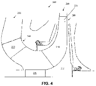
[0028] FIG. 4 is a schematic cross-sectional view along a longitudinal axis
of one stage
of a multi-stage, centrifugal flow turbomachine according to one embodiment of
the present
invention; and
7
CA 02900706 2015-08-07
WO 2014/143426
PCT/US2014/013579
[0029] FIGS. 5A-5C show schematic views of stationary vane arrangements
according to
two embodiments of the present invention.
DETAILED DESCRIPTION OF THE INVENTION
[0030] For purposes of the description hereinafter, the terms "upper",
"lower", "right",
"left", "vertical", "horizontal", "top", "bottom", "lateral", "longitudinal",
and derivatives
thereof shall relate to the invention as it is oriented in the drawing
figures. However, it is to
be understood that the invention may assume alternative variations and step
sequences,
except where expressly specified to the contrary. It is also to be understood
that the specific
devices and processes illustrated in the attached drawings, and described in
the following
specification, are simply exemplary embodiments of the invention. Hence,
specific
dimensions and other physical characteristics related to the embodiments
disclosed herein are
not to be considered as limiting.
[0031] As described above, rotating blades 60 in a conventional
turbomachine 10 are
excited into resonant vibrations by a) upstream stator strut and/or vane wakes
and potential
flow interaction with downstream struts and vanes , b) other inhomogeneities
in the flow
stream formed by non-uniform circumferential pressure distribution, c)
acoustic pulsations
either at rotating blade passing frequency and/or d) from vortex shedding from
the struts or
vanes, in turn causing coincident acoustic resonance of the gas within the
casing. Rotating
blades 60 can be excited to a large amplitude when a blade modal frequency
corresponds to
the shaft rotational frequency multiplied by the harmonic number of the flow
inhomogeneity
seen by the rotating blade 60.
[0032] In order to overcome these deficiencies of the prior art, the
present invention
provides a stationary vane arrangement adapted for homogenizing the flow into
the rotating
blades to reduce the destructive forces and increase the application range.
The present
invention provides a stationary vane arrangement adapted for reducing rotor
blade and/or disk
excitation by homogenizing the gas flow stream, both for flow and acoustic
pulsations, as
well as reducing the effect of vortices shed-off the stationary vanes.
[0033] With reference to FIG. 4, a turbomachine 200 includes a stationary
vane
arrangement adapted for reducing or eliminating resonant vibrations caused by
inhomogeneities in the flow stream due to vortex shedding at the trailing edge
of stator struts.
FIG. 4 illustrates a single stage of a turbomachine 200; however, one of
ordinary skill in the
art will understand that specific components illustrated in FIG. 4 can be
easily adapted for
use in multi-stage turbomachines, such as a multi-stage, centrifugal-flow
compressor.
8
CA 02900706 2015-08-07
WO 2014/143426
PCT/US2014/013579
[0034] With continuing reference to FIG. 4, turbomachine 200 includes a
plurality of
rotating blades 210 circumferentially arranged around a disk 215 that is
rotatable with shaft
220. In an embodiment where turbomachine 200 has multiple stages (not shown),
rotating
blades 210 are disposed in multiple stages along the axial length of shaft
220. In another
embodiment, rotating blades 210 may be fixedly coupled to shaft 220 such that
rotating
blades 210 rotate with the rotation of shaft 220. Rotating blades 210 rotate
adjacent to a
plurality of stationary vanes 230 (i.e., stationary vane arrangement) attached
to a stationary
tubular casing 240. Working fluid, such as gas mixture, moves from an inlet
end 250 to an
outlet end 260 of turbomachine 200. A row of stationary vanes 230 provided at
inlet end 250
channels the working fluid into a row of rotating blades 210 at outlet end 260
of
turbomachine 200. The number of stationary vanes 230 may correspond to the
number of
rotating blades 210. Alternatively, the number of stationary vanes 230 may be
higher or
lower than the number of rotating blades 210. Desirably, the number of
rotating blades 210 is
not equal to the number of stationary vanes 230 in order to remove circular
and torsional
modes when all blades vibrate in-phase along a circular line. Stationary vanes
230 may have
an even or odd number of individual vanes. Due to aerodynamic concerns,
stationary vanes
230 are desirably provided proximate to rotating blades 210 to enhance mixing
and reduce
effect of vortices shed off of the vanes. This arrangement reduces acoustic
pressure
pulsations and direct pressure loads on rotating blades 210.
[0035] Diffuser 280, along with optional diffuser vanes 270, is provided at
the outlet of
rotating blades 210 for homogenizing the fluid flow coming off rotating blades
210. Diffuser
280 is desirably provided at outlet end 260 of turbomachine 200. Each diffuser
280
optionally has one or more diffuser vanes 270 extending across a casing for
channeling the
working fluid to stationary vanes 230 of the next successive stage. Diffuser
vanes 270 are
desirably spaced apart equally around the circumference of the diffuser
casing.
[0036] Stationary vanes 230 extend across an interior portion of stationary
casing 240 for
directing the working fluid to rotating blades 210. Stationary vanes 230 are
spaced apart
circumferentially with equal spacing between individual vanes around the
perimeter of
stationary casing 240 for ensuring desirable aerodynamic performance. In order
to overcome
the deficiency of the prior art design that leads to the creation of
fundamental wake passing
frequencies downstream of the trailing edges of conventional struts, the
present invention
incorporates a stationary vane arrangement adapted for reducing vibratory
excitation of one
or more of the resonant vibratory modes of the rotating blades as the
turbomachine is
operated over various operating speeds.
9
CA 02900706 2015-08-07
WO 2014/143426
PCT/US2014/013579
[0037] With reference to FIGS. 5A-5C, various configurations of stationary
vane
arrangements are shown in accordance with a plurality of embodiments of the
present
invention. Each of the FIGS. 5A-5C shows a schematic view of a plurality of
stationary
vanes 230. In each embodiment, stationary vanes 230 have a pair of opposing
longitudinal
surfaces 300a, 300b. As shown in FIGS. 5A-5C, opposing longitudinal surfaces
300a, 300b
of each stationary vane 230 are substantially linear and substantially
parallel to each other. In
alternate embodiments, opposing longitudinal surfaces 300a, 300b of each
stationary vane
230 may be streamlined to have a specific aerodynamic profile.
[0038] Each stationary vane 230 has a trailing edge 310 provided at its
downstream end
and a leading edge 320 provided at its upstream end. In contrast to the prior
art designs
where the trailing edge of each stationary vane is shaped identically to each
adjacent trailing
edge, stationary vanes 230, shown in FIGS. 5A-5C, include a modified design
for reducing
or cancelling out the forces generated by the stator wake to reduce the
vibratory excitation of
one or more of the resonant vibratory modes of the rotating blades 210.
[0039] With specific reference to FIG. 5A, stationary vanes 230 having an
alternating
pattern of trailing edges 310 and leading edges 320 are shown for a stator
having an odd
number of stationary vanes 230. In one preferred and non-limiting embodiment,
stationary
vanes 230 are grouped into groups of two or three to alternate the homogenized
wake pattern.
For example, a stator having 21 stationary vanes 230 arranged as indicated in
FIG. 5A has a
repeating pattern of groups of three stationary vane sets. Stationary vanes
230 are desirably
positioned with equal radial separation between adjacent vanes. Additionally,
all stationary
vanes 230 are arranged at a same longitudinal position within the stationary
casing 240 such
that all stationary vanes 230 are equally distanced from rotating blades 210
(not shown in
FIG. 5A). Stationary vanes 230 are arranged such that a first half of
stationary vanes 230
have trailing edges 310 and leading edges 320 that terminate at a
substantially rounded end
330, similar to stationary vanes 80 shown in FIG. 3. The second half of
stationary vanes 230
of the stationary vane arrangement shown in FIG. 5A have trailing edges 310
and leading
edges 320 terminating at a tapered end 340. The two types of stationary vanes
230 are
arranged such that each stationary vane 230 having a rounded end 330 is
positioned between
stationary vanes 230 having tapered end 340. Tapered end 340 is formed by
cutting a part of
one longitudinal surface 300a, 300b at an angle with respect to the opposing
longitudinal
surface 300a, 300b. Trailing edge 310 and leading edge 320 of each stationary
vane 230
may have tapered end 340 tapering in a same direction or opposing directions,
as shown in
FIG. 5A.
CA 02900706 2015-08-07
WO 2014/143426
PCT/US2014/013579
[0040] Leading edges of each diffuser vane (not shown) are desirably formed
in a similar
manner. For example, leading edges of each diffuser vane may have an
alternating pattern
where some diffuser vanes have a leading edge that is substantially rounded
while the
remaining diffuser vanes have tapered leading edges.
[0041] With specific reference to FIG. 5B, stationary vanes 230 having an
alternating
pattern of trailing edges 310 and leading edges 320 are shown for a stator
having an even
number of stationary vanes 230. Similar to the embodiment shown in FIG. 5A,
stationary
vanes 230 are grouped into groups of two or three to alternate the homogenized
wake pattern.
For example, a stator having 20 stationary vanes 230 arranged as indicated in
FIG. 5B has a
repeating pattern of groups of two stationary vane pairs. Stationary vanes 230
are desirably
positioned with equal radial separation between adjacent vanes. Additionally,
stationary
vanes 230 are arranged in an alternating offset longitudinal position within
the stationary
casing 240 such that some stationary vanes 230 are closer to rotating blades
210 (not shown
in FIG. 5A) than other stationary vanes 230. Stationary vanes 230 are arranged
such that the
first half of stationary vanes 230 have trailing edges 310 and leading edges
320 that terminate
at a substantially rounded end 330, similar to stationary vanes 230 shown in
FIG. 5A. The
second half of stationary vanes 230 of the stationary vane arrangement shown
in FIG. 5B
have trailing edges 310 and leading edges 320 terminating at a tapered end
340, similar to the
stationary vane arrangement shown in FIG. 5A. The two types of stationary
vanes 230 are
arranged such that each stationary vane 230 having a rounded end 330 is
positioned between
stationary vanes 230 having tapered end 340. Stationary vanes 230 having
rounded end 330
are set back longitudinally relative to stationary vanes 230 having tapered
end 340. In this
arrangement, stationary vanes 230 having rounded end 330 are located closer to
rotating
blades 210 (not shown in FIG. 5B) than stationary vanes 230 having tapered end
340.
Tapered end 340 is formed by cutting a part of one longitudinal surface 300a,
300b at an
angle with respect to the opposing longitudinal surface 300a, 300b. Trailing
edge 310 and
leading edge 320 of individual stationary vane 230 may have tapered end 340
tapering in a
same direction or opposing directions, as shown in FIG. 5B.
[0042] With specific reference to FIG. 5C, stationary vanes 230 having an
alternating
pattern of trailing edges 310 and leading edges 320 are shown for a stator
having an even
number of stationary vanes 230 in accordance with another embodiment. Similar
to other
embodiments, stationary vanes 230 are grouped into groups of two or three to
alternate the
homogenized wake pattern. For example, a stator having 20 stationary vanes 230
arranged as
indicated in FIG. 5C has a repeating pattern of groups of two stationary vane
pairs.
11
CA 02900706 2015-08-07
WO 2014/143426
PCT/US2014/013579
Stationary vanes 230 are desirably positioned with equal radial separation
between adjacent
vanes. Additionally, all stationary vanes 230 are arranged at a same
longitudinal position
within the stationary casing 240 such that all stationary vanes 230 are
equally distanced from
rotating blades 210 (not shown in FIG. 5C). All stationary vanes 230 of the
stationary vane
arrangement shown in FIG. 5C have trailing edges 310 and leading edges 320
terminating at
a tapered end 340. Tapered end 340 is formed by cutting a part of one
longitudinal surface
300a, 300b at an angle with respect to the opposing longitudinal surface 300a,
300b. In this
embodiment, tapered ends 340 are arranged such that they are inclined at
mutually opposing
angles. In other words, stationary vanes 230 are arranged such that tapered
ends 340 are
alternately cut between adjacent stationary vanes 230. In a similar manner,
leading edges of
each diffuser vane (not shown) are desirably formed in a similar manner. For
example,
leading edges of each diffuser vane may have an alternating pattern where
diffuser vanes
have mutually-opposed tapered leading edges.
[0043] The above-described stationary vane arrangements are adapted for
reducing the
excitation of rotating blades 210 and disk 215 by dehomogenizing the
successive wakes
within the flow stream and reducing the effect of acoustic pulsations and
vortices shed-off
stationary vanes 230. The creation of excitation at fundamental wake passing
frequencies
downstream of trailing edges 310 of the stationary vanes 230 is minimized,
thereby reducing
the vibratory response of one or more of the resonant vibratory modes of the
rotating blades
as the turbomachine is operated over various operating speeds. In addition,
response to
acoustic excitation is mitigated by the stationary vane arrangements described
above.
[0044] To determine whether forces generated by the wakes coming off
stationary vanes
230 cancel each other for the entire rotor at a given operating speed, the
number of rotating
blades 210 on the rotor is considered with regard to the number of stationary
vanes 230
interacting with the rotating blades 210. For example, for a disk 215 or
coupled blade
structural mode, such as a five-diameter mode in a 15-bladed impeller,
exciting forces
shedding off stationary vanes 230 cancel for all stationary vane arrangements
except for a 10-
vaned or 20-vaned stator. Forces do not cancel if the natural frequency is
equal to 10 times
the operating speed with a 10-bladed stator, or with either a 10- or 20-bladed
stator if the
structural frequency is equal to 20 times the operating speed. The parametric
equations
illustrating embodiments where phase cancellation cannot be achieved are
represented as
follows:
Equation (1) Equation (2)
Not at Disk Critical Speeds: At Disk Critical Speeds:
12
CA 02900706 2015-08-07
WO 2014/143426
PCT/US2014/013579
(a) ly = SI lz = Bl= n (a) For B >1
(b) y = S = h (b) y=S=h=n
(c) f, = y = S = co (c) f, = n = co
where:
B = number of rotating blades
S = number of stationary elements
f, = natural frequency at speed, Hz
h = harmonic of speed
n = number of diameter nodal lines
y & z = integers > 0
= rotating speed, Hz
[0045] Non-homogenous flow downstream of the stationary vane arrangement
can be
caused by a plurality of factors relating to the spinning modes of acoustic
pressure pulsations
at rotating blade passing frequency. The interaction of rotating blades 210
both upstream and
downstream of stationary vanes 230 affects acoustic pulsations at rotating
blade passing
frequency. In general, reflecting acoustic waves are generated within disk 215
having a
diametral pattern with the number of diameters equal to an absolute value of
the difference
between the number of rotating blades 210 and stationary vanes 230. For
example, in a
turbomachine 200 with 15 rotating blades 210 and 10 upstream stationary vanes
230, there is
a 5-diameter spinning acoustic mode (115 ¨ 101 = 5). Similarly, a 5-diameter
spinning
acoustic mode is also present in a turbomachine 200 having 15 rotating blades
210 and 20
upstream stationary vanes 230 (115 ¨ 201 = 5). The excitation frequency causes
resonance if
20 times rotating speed is equal to a 5-diameter disk or blade coupled mode
frequency. In
both cases, the spinning mode relative to rotating blades 210 occurs at a
frequency equal to
15 times the rotating speed. This acoustic interaction excitation is normally
only of concern
if the same diametral pattern acoustic mode of the gas is simultaneously
coincident with
rotating blade passing frequency, at the resonant speed of the spinning mode
within the
rotating element. Another acoustic excitation of gas modes can be caused by
vortex shedding
frequency from the trailing edges of stationary vanes 230. In turn, the
acoustic mode
frequency with the same mode shape, i.e., number of diameters, could be at a
resonant speed
if equal to a disk or blade coupled mode frequency plus or minus the number of
diameters
times shaft speed. Axial flow turbomachines typically have a low risk of
blade/vane
interaction resonance for disk modes because of the relatively high numbers
used in the
above equations and the high difference between the number of rotating blades
and stationary
vanes. Accordingly, any design that has a disk critical speed or interaction
resonance below
operating speed has a limited number of resonance cycles while traversing low
speeds.
13
CA 02900706 2015-08-07
WO 2014/143426
PCT/US2014/013579
Nonetheless, all of these three potential sources of excitation can be
mitigated by the proper
selection of the number of rotating blades 210 and design of stationary vanes
230 in
accordance with the embodiments described herein.
[0046] While the above-described stationary vane arrangement has been
described with
reference to a turbomachine, such as a compressor, the design is equally
applicable to any
other turbomachine utilizing bladed disk construction, including, but not
limited to, radial-
inflow turbines, fans, axial/centrifugal compressors, gas turbines, jet
engines, turbo pumps,
expanders, cooling flow elements in motors, and generators. Those skilled in
the art may
make modifications and alterations to these embodiments without departing from
the scope
and spirit of the invention. For example, it is to be understood that this
disclosure
contemplates that, to the extent possible, one or more features of any
embodiment can be
combined with one or more features of any other embodiment. Accordingly, the
foregoing
description is intended to be illustrative rather than restrictive. The
invention described
hereinabove is defined by the appended claims and all changes to the invention
that fall
within the meaning and the range of equivalency of the claims are to be
embraced within
their scope.
14