Note: Descriptions are shown in the official language in which they were submitted.
Overflow Vent Scoop for Flush Valve
BACKGROUND OF THE INVENTION
FIELD OF THE INVENTION
[0003] The invention relates to flush valves for toilets, urinals and the
like, and more
particularly to a modification to the design of such valves to provide a scoop
or cover to be
placed over the opening to an overflow tube or to a vent tube within the flush
valve to help to
divert water that may block an overflow tube and facilitate escape of air that
may be otherwise
trapped within the valve body, the valve throat and/or the toilet manifold.
DESCRIPTION OF RELATED ART
[0004] Toilets and toilet assemblies for removing solid and liquid
human waste are well
known. Typically, toilets incorporate three systems that work together to
perform the flushing
action: (1) internal water channels of the toilet bowl, (2) the flush
mechanism, and (3) the refill
mechanism. Working in concert, these three systems enable the flushing
function of the toilet.
[0005] Usually, a toilet tank, positioned over the back of the toilet bowl
in a two-piece
toilet assembly or in the upper part of a one-piece assembly with a tank
portion, holds water
that is used to both initiate flushing of waste from the toilet bowl, through
a trapway and into a
sewage drain line, and refill the bowl with fresh water. When a user wants to
flush the toilet,
the user pushes down on a flush lever or other flush actuator on the outside
of the tank, which is
connected on the inside of the tank typically to a movable chain and/or lever
or mechanical
flush valve actuator. When the flush lever is depressed on the outside of the
tank, the chain or
lever on the inside of the tank acts to lift and open a flush valve, enabling
water to flow from
the tank into the bowl to initiate a toilet flush cycle. In some toilet
designs the toilet bowl does
not have a tank on the rear portion of the tank, but instead may have an in-
line flush valve
1
Date Recue/Date Received 2020-05-27
CA 02900809 2015-08-10
WO 2014/127371 PCT/US2014/016961
mounted in a casing on the rear portion of the toilet and in communication
with an incoming
source of water.
100061 In many toilet designs, water flows from a flush valve directly
into the bowl inlet,
and is then dispersed into a rim channel, a jet channel(s), an opening and/or
directly into the
toilet bowl through a manifold area located beneath the toilet bowl inlet. The
water releases
from the valve into the bowl through the toilet bowl inlet rather quickly,
with flow from the
flush valve entering the bowl typically lasting only approximately on half to
four seconds. The
water flows into the bowl either directly, from the rim, channel and/or down a
jet channel(s)
within the bowl which introduces water into the bottom of the toilet bowl
through a siphon jet
outlet. The siphon jet releases most of the water into the trapway, which
initiates siphon action.
The siphoning action draws all the water and waste out the bowl, and into the
trapway. The
waste and water continues through the other end of a generally U-shaped
trapway and is
released into the wastewater or sewage drain line connected at the base of the
toilet.
100071 Once the tank is emptied during the flush, the flush valve closes,
and a floating
mechanism(s) or other similar tripping device, depending on the flush valve
and tank design,
initiates opening of a filler valve in a toilet design having a fillable tank.
A filler valve provides
fresh water to both the tank and the bowl through separate flows. Eventually,
the tank fills with
water to a level high enough to cause the float to rise, thus shutting off the
fill valve. At this
point, the flushing cycle is complete.
100081 Government agencies have continually demanded that water use for
flushing be
reduced. Much of the focus in recent years has been to reduce the water demand
required by
toilet flushing operations. In order to illustrate this point, the amount of
water used in a toilet
for each flush has gradually been reduced by governmental agencies from 7
gallons/flush (prior
to the 1950's), to 5.5 gallons/flush (by the end of the 1960's), to 3.5
gallons/flush (in the
1980's). The National Energy Policy Act of 1995 mandates that toilets sold in
the United States
can use water in an amount of 1.6 gallons/flush (6 liters/flush) or less.
100091 One attempt in the art to produce a more reliable, more efficient
and more powerful
1.6 gallon (6 liter) gravity flush toilet, known as a "high-performance
toilet" (IIPT), while
overcoming the drawbacks in existing toilet technology by increasing the
hydraulic energy
.. available during the flushing operation, can be found in U.S. Patents Nos.
6,901,610 entitled,
"High Performance Valve Assembly For Toilets"; U.S. Patent No. 6,728,975
entitled, "High
Performance Flush Valve Assembly"; and U.S. Patent No. 6,715,162 for "Toilet
Assembly,"
2
commonly owned with the present application.
[0010] Flush valve assemblies for water tanks of toilets are described
in U.S. Patents Nos.
6,901,601, 6,723,975 and 6,715,162. These patents describe a flush valve
having a valve body
with a base sleeve portion including a radiused inlet to increase the
discharge coefficient of the
valve opening. A flush cover member is coaxially and slidably mounted with
respect to the
valve body so that the valve opening is created therebetween when the flush
cover member is
removed from the valve body via reciprocating motion. The flush cover member
is slidably
.. movable between a first position, wherein the flush cover member is seated
on the base sleeve
portion of the valve body and thereby obstructs water flow through the valve
opening, and a
second position, wherein the second valve member is removed from the base
sleeve portion of
the valve body to permit water flow through the valve opening. A sealing
member is provided
to ensure a proper seal when the flush cover member is in the first position,
and a guiding
means is provided that properly aligns and guides the flush valve cover
relative to the valve
body. The flush valve assembly also includes a trip release mechanism that
releases the effects
of the flush lever on the flush cover member when the flush cover member
reaches its second
position, thereby returning the flush cover member to its first rest position
prior to the flush
lever returning to its own corresponding rest position. In this configuration,
the disclosed flush
valve assembly ensures compliance with the mandated water requirements and
simultaneously
provides enhanced cleanliness and waste removal capabilities. The flush valve
assembly
achieves these functions and also releases the effect of the flush lever so
that the valve opening
can close before the expiration of a regulatory minimum "hold down" time (1
second without
exceeding the total water per flush mandate of 1.6 gallons (6 liters)).
[0011] Alternative technologies proposed for providing adequate flush valve
efficiency for
high-performance toilets may be found in U.S. Patent No. 7,676,858, which
proposes use of a
flush valve that has a valve body with a valve seat that defines a flow
passage having a portion
of its interior flow profile that narrows in a non-linear manner away from the
valve seat such
that the inner surface of the valve seat in the non-linear portion can be
defined by a polynomial
expression, i.e., the valve body has a non-linearly curved inner surface.
[0012] U. S . Patent No. 8,079,095, owned by the present applicant,
discloses a flush valve
that accomplishes water conservation and flush efficiency, as well as the
performance goals
3
Date Recue/Date Received 2020-05-27
CA 02900809 2015-08-10
WO 2014/127371 PCT/US2014/016961
noted above, by providing a more efficient combination of a radiused inlet and
an optional
elevated valve body. The flush valve assembly disclosed therein may also have
a "poppet" or
centrally aligned and guided buoyant float cover for the valve body. This
particular design is
highly effective if an upwardly buoyant and centrally guided flush cover is
used, because the
upward lifting of such a cover provides for water intake into the valve
opening in a 3600
configuration. That is, when the buoyant cover lifts, it allows for water to
flow in from all
directions into the valve opening for supplying water from the toilet tank to
the toilet bowl.
100131 As some problems are still encountered when using elevated valve
bodies having an
optimal radiused inlet designed to enhance flow and maximize hydraulic energy
through the
valve body with a standard flapper-type valve cover, other improvements have
also been made
in the art. Flush valve body assemblies having a radiused inlet and elevated
valve body, used
with the above-noted, poppet, centrally-guided flush cover, are able to handle
the increased
efficiency and maximized flow through the valve body at reduced volumes of
water so as to be
useful as high-performance flush valves working with HPT toilets having toilet
bowl designs
and flush pathways that achieve the 1.6 gallons/flush water conservation
standards, some of
which may be qualified as high-efficiency toilets (HET) which provide
effective flushing at as
low as about 1.28 gallon per flush or even lower.
100141 Using a standard two-inch inlet, the flush volume through a high-
efficiency flush
valve designed to function with high-efficiency toilets (HETs) is very high,
even though the
volume in the toilet tank available for flushing is lower than prior art
traditional toilets. A
traditional flapper valve cover's performance used with such a valve body and
a two-inch inlet
can be affected in terins of its ability to close when. appropriate, sometimes
closing prematurely,
and in terms of its ability to re-open. This problem can sometimes be
exacerbated in a radiused
inlet valve body design, because the extension of the inlet opening due to the
presence of the
radius, which is optimized for high-efficiency flow through the valve body.
This can require an
even larger sized flapper to cover the opening created by the radius thereby
contributing to
buoyancy issues affecting opening and closing of the flapper cover. These
factors can combine
to make it difficult to properly open and close a standard flapper on a valve
assembly
configured for use in an HPT or, preferably an HET and having an elevated
valve body and
radiused inlet, even in comparison to standard low profile, non-elevated flush
valve bodies
having standard flapper-type valve covers.
4
[0015] Other issues encountered in flush valve designs arise when such
flush valves,
whether suitable for high-efficiency toilets or not, are optimized for flow
design, but have
outlets which, when installed introduce fluid flow directly into an inlet
chamber of a toilet bowl
having a lower floor which lies in a plane perpendicular to the flow coming
out of the flush
valve outlet. The impact of the contact between the high flow rate through the
valve caused by
flushing against the floor of the inlet chamber of the toilet bowl introduces
undesirable
turbulence which reduces the hydraulic energy available from the water exiting
the outlet of the
flush valve. Prior art designs are available from the owner of the present
application in which a
fitting is used on the bottom of a flush valve outlet to divide and direct the
flush valve outlet
flow into two separate directions so as to introduce flow into the a rim area
and into the jet area
of the toilet bowl. Such designs do avoid some of the impact issue, for
certain particular high-
efficiency toilet designs.
[0016] Improvements in such designs are described in U.S. Patent No.
8,266,733, of the
applicant hereto, which discloses a valve having an elevated valve body that
includes a wall
extending between the upper inlet end and the lower outlet end of the valve
body with an
interior surface that defines a flow path extending generally longitudinally
through the valve
body with a generally circular transverse cross-section. At least a portion of
the wall is
downwardly linearly tapered so that there is a decreasing valve body diameter
and the tapered
wall portion is positioned below the radiused inlet portion. The patent also
describes a valve
flapper with a bulb configuration more readily adaptable to address the
buoyancy issues that
arise from the high rate of flow through the valve body.
[0017] In a further improvement, co-pending U.S. Provisional Application
14/038,748
describes improved flush valves including those that may
have an elevated valve body, wherein the valves incorporate a flush line that
connects a flush
actuating device to a flush valve cover. The flush line is for raising and
lowering the flush
valve cover upon actuation of the assembly. A float is connected to the flush
valve cover via a
the float line or is positioned along the flush line. The float is
sufficiently buoyant so as to be
capable of resisting the force of flowing water and keeps the flush valve
cover open so as to
allow flush water to pass through the valve body before closing the flush
valve cover when the
valve body is installed on a toilet.
[0018] Such improvements in flow through flush valves, especially for
HPT, and preferably
HET toilet assemblies create additional challenges to improve efficiencies in
flow to continue
5
Date Recue/Date Received 2020-05-27
CA 02900809 2015-08-10
WO 2014/127371 PCT/US2014/016961
to improve valve and toilet flush performance while enabling continued
conservation of water
use. Flow through many of the above-noted high flow valves, which include
elevated valve
bodies, linearly or non-linearly tapered designs, poppet designs and/or use
radiused inlets, can
still have issues in terms of turbulence or high flow of water blocking the
entrance to the
overflow tube of the valve and/or preventing air from escaping the valve, such
as through the
overflow or vent tubes in the valve designs. As flow rates through the valve
are more laminar
and fast, as the valve opens to allow water to rush through the valve body
towards the toilet, air
from within the system can cause obstruction to the benefit achieved by the
incoming flow. If
the air can pass easily out of the system, any such impact can be minimized.
However, the
force of the flow can back up the water into the overflow and/or vent tubes
from within the
valve body in various designs, a typical exit path for air, thus blocking an
easy outlet passage
for the trapped air. The less trapped air in the incoming flow the better. As
a result, there is a
need in the art for a way to reduce any negative impact to air release without
negatively
compromising the enhanced flow rates and flow dynamics achievable by the above-
noted
improved high efficiency flush valves.
BRIEF SUMMARY OF THE INVENTION
[00191 The invention includes a vent cover designed for use with a flush
valve assembly,
comprising a vent cover wall including an upper portion, a lower portion
configured to define a
vent cover inlet opening for receiving air passing upwardly from within a
valve body and/or
from within a toilet through a toilet inlet when the vent cover is installed
on a valve body, an
exterior surface, and an interior surface defining a vent cover passage for
air passing upwardly
from the vent cover inlet opening, wherein at least the upper portion of the
vent cover wall is
configured for contacting an interior surface of a valve body at a location
above an inlet of an
overflow tube or a vent tube on a valve body when the vent cover is installed
on a valve body
and wherein the valve cover wall is configured to at least partially divert
flow of fluid :from.
entering an inlet of an overflow tube or a venting tube on a valve body when
the vent cover is
installed on a valve body.
100201 The vent cover wall may also be configured to allow air and/or
fluid entering the
vent cover from. the vent cover inlet opening to pass upwardly through the
vent cover passage
and to exit the vent cover into an inlet of an overflow tube or a venting tube
of a valve body
when the vent cover is installed on a valve body.
6
CA 02900809 2015-08-10
WO 2014/127371 PCT/US2014/016961
[00211 The vent cover may be formed so as to comprise a polymeric
material. The vent
cover wall is preferably curved, and has a body portion below the upper
portion of the vent
cover wall and above the lower portion of the vent cover wall and the inlet
opening. The vent
cover wall also preferably has a generally semi-circular configuration in
transverse cross-
section and a radius measured in a transverse direction across the vent cover
such that the
passage through the vent cover within the body portion of the vent cover wall
also has a
generally semi-circular configuration. The vent cover wall is also preferably
formed so as to
have an outer edge along at least the upper portion and the body portion of
the vent cover wall.
The radius of the vent cover wall may be constant in the body portion of the
vent cover wall or
the vent cover wall and/or its outer edge can taper so as to conform to an
interior surface of a
valve body wall, in which case the radius would decrease along the body
portion from the upper
portion to the lower portion. The upper portion of vent cover wall may also be
preferably
arcuately curved such that the radius of the vent cover wall decreases along
the upper portion
moving from the body portion of the vent cover wall towards the edge of the
upper portion of
the vent cover wall. The outer edge of the vent cover wall is preferably
configured to meet an
interior surface of a valve body of a flush valve in facing engagement when
the vent cover is
installed in a flush valve.
100221 The vent cover may be formed of a material capable of being
affixed to an interior
surface of a valve body of a flush valve by an adhesive, ultrasonic welding
and/or polymeric
heat welding. The vent cover may also be formed of a material capable of being
heat molded to
an interior surface of a valve body of a flush valve.
100231 In one embodiment, the vent cover also comprises projections that
extend outwardly
from the exterior surface of the vent cover wall and which are configured to
engage a feature of
a valve body and/or an interior surface of a valve body of a flush valve upon
installation of the
vent cover.
100241 The invention also includes a flush valve assembly that comprises
a valve body that
has an upper inlet end having an inlet opening therethrough for receiving
fluid into the flush
valve body, a lower outlet end having an outlet opening therethrough for
allowing fluid to exit
the flush valve body, and a valve body wall extending between the upper inlet
end and the
lower outlet end and having an interior surface defining a flow path that
extends generally
longitudinally through the valve body from the inlet opening to the outlet
opening, a valve body
cover capable of opening and closing over the inlet opening of the valve body,
an overflow or
7
CA 02900809 2015-08-10
WO 2014/127371 PCT/US2014/016961
venting tube, having an inlet opening in communication with the flow path of
the valve body
and an outlet opening for releasing air and/or fluid from within the valve
body, a vent cover
having a vent cover wall, wherein the vent cover wall has with an upper
portion, a lower
portion defining an inlet opening for receiving air passing upwardly from
within the valve body
flow path and/or from a toilet through a toilet inlet, an exterior surface,
and an interior surface
defining a vent cover passage for receiving air and/or liquid from the inlet
opening of the vent
cover, wherein at least the upper portion of the vent cover wall contacts the
interior surface of
the valve body at a location above the inlet opening of the overflow or
venting tube and the
passage is configured to at least partially divert flow of fluid from entering
an inlet of the
overflow or venting tube on the valve body when the vent cover is installed on
a valve body.
100251 The vent cover wall may also be configured to allow air and/or
fluid entering the
vent COM from the vent cover inlet opening to pass upwardly through the vent
cover passage
and to exit the vent cover into an inlet of the overflow or venting tube of
the valve body.
100261 The valve body design may vary, and can be formed as a HET or HPT
valve body.
In one embodiment, it may have a valve body upper inlet end formed so as to
comprise a
radiused inlet. The valve body in this or another embodiment may have an
elevated valve body,
in that the largest diameter of the valve body is smaller than the height of
the valve body. In a
further embodiment, the valve cover may be a buoyant poppet float coaxially
mounted in the
valve body for reciprocating motion with respect to said valve body along a
guide member.
100271 The valve body may also have at least a portion of the interior
surface of the valve
body wall downwardly linearly tapered so as to have a decreasing valve body
diameter as
measured transversely across the valve body. The valve body wall may also
comprise an upper
inlet section, a base section for attaching to a toilet tank floor, and an
extension section situated
between the inlet section and the base section, wherein at least one of an
interior surface of the
base section and of the extension section is tapered so as to have a linearly
decreasing diameter
from an upper end of each section in a direction toward a lower end of each
section, wherein
the diameters are measured transversely across each section.
100281 The valve body of the assembly in another embodiment may be an
elevated valve
body, wherein the upper inlet end of the valve body further comprises a
radiused inlet and the
tapered portion of the valve body wall is below the radiused inlet portion. In
another
embodiment, the valve body wall may comprise an upper inlet section, a base
section for
attaching to a toilet tank floor, and an extension section situated between
the inlet section and
8
CA 02900809 2015-08-10
WO 2014/127371 PCT/US2014/016961
the base section, wherein, at least one of an interior surface of the base
section and of the
extension section is tapered so as to have a linearly decreasing diameter from
an upper end of
each section in a direction toward a lower end of each section, wherein the
diameters are
measured transversely across each section.
100291 In the flush valve assembly, the vent cover may have a wall that is
curved and have
a vent cover wall body portion below the upper portion of the vent cover wall
and above the
lower portion of the vent cover wall and the vent cover inlet opening, wherein
the vent cover
wall has a generally semi-circular configuration in transverse cross-section
and has a radius
measured in a transverse direction across the vent cover such that the vent
cover passage within
the body portion of the vent cover wall also has a generally semi-circular
cross-sectional
configuration. The radius of the vent cover wall may be constant in the body
portion of the
vent COM wall if the vent cover wall is generally linear and perpendicular, or
the vent cover
wall can be tapered to conform to a tapered interior surface of a valve body,
in which case the
radius may decrease from the upper portion to the lower portion of the vent
cover wall along
the body portion of the vent cover wall. Further, the upper portion of vent
cover wall may be
arcuately configured to curve towards the interior surface of the valve body
so that the radius of
the vent cover wall, measured transversely across the vent cover, decreases
along the upper
portion of the vent cover wall as the vent cover wall approaches the interior
surface of the valve
body.
100301 In the assembly, the vent cover wall may also have an outer edge
along the body
portion and the upper portion of the vent cover wall, wherein the outer edge
is configured for
meeting the interior surface of the valve body in facing engagement. The vent
cover may be
affixed to the interior surface of the valve body by an adhesive, ultrasonic
welding and/or
polymeric heat welding or can be heat molded to the interior surface of the
valve body. In the
assembly, the vent cover may be molded as a unitary part of the valve body.
100311 The vent cover in the assembly may also further comprise
projections extending
outwardly from the exterior surface of the vent cover wall which are
configured for engaging a
feature of the valve body and/or the interior surface of the valve body.
100321 The vent cover can also have varying lengths as measured
longitudinally through the
valve cover. In embodiments herein, the vent cover can be made to have a
length as measured
longitudinally from the bottom of an overflow or venting tube inlet to the
bottom of the vent
cover body, i.e., at the vent cover inlet, of about 0 to about 100 mm below
the bottom of an
9
CA 02900809 2015-08-10
WO 2014/127371 PCT/US2014/016961
inlet of an overflow or venting tube, preferably about 10 mm to about 70 mm
below the bottom
of an inlet of an overflow or venting tube, and more preferably about 25 to
about 65 mm below
the bottom of the inlet of an overflow or venting tube.
100331 in one embodiment of the assembly, an upper inlet end of the valve
body may
comprise a radiused inlet, the valve body may be an elevated valve body, and
the valve cover
configured as a buoyant poppet float coaxially mounted in the valve body for
reciprocating
motion with respect to said valve body along an guide member, wherein the vent
cover further
comprises projections extending outwardly from the exterior surface of the
wall which are
configured for engaging the guide member of the valve body.
100341 In a further embodiment herein, the invention includes a flush valve
assembly for a
toilet tank, the flush valve assembly, comprising, a flush valve having a
valve body comprising
an upper inlet end having an inlet opening therethrough for receiving fluid
into the flush valve
body, wherein the upper inlet is a radiused inlet, a lower outlet end having
an outlet opening
therethrough for allowing fluid to exit the flush valve body, and a valve body
wall extending
between the upper inlet end and the lower outlet end and having an interior
surface defining a
flow path that extends generally longitudinally through the valve body from
the inlet opening to
the outlet opening, wherein the valve body has an elevated base section; and a
movable poppet
cover capable of moving in a coaxial, reciprocating manner; and a vent cover
having a vent
cover wall, wherein the vent cover wall has with an upper portion, a lower
portion defining an
inlet opening for receiving air passing upwardly from within the valve body
flow path and/or
from a toilet through a toilet inlet, an interior surface defining a vent
cover passage for
receiving air from the inlet opening of the vent cover, wherein at least the
upper portion of the
vent cover wall contacts the interior surface of the valve body wall at a
location configured to at
least partially divert flow of fluid in a valve body when the vent cover is
installed and/or to
facilitate escape of trapped air.
100351 In one embodiment of such a flush valve assembly, the flush valve
poppet cover
may comprise a guide rod and the valve body may comprise a web structure
having a central
hole configured to receive the guide rod, and the guide rod is capable of
reciprocatably and
coaxially moving within the hole so as to raise the poppet cover to allow
fluid to flow into the
inlet of the flush valve in an open position and to allow for aligned axial
movement of the
poppet cover when the flush valve moves to a closed position.
CA 02900809 2015-08-10
WO 2014/127371 PCT/US2014/016961
BRIEF DESCRIPTION OF THE SEVERAL VIEWS OF THE DRAWING(S)
100361 The foregoing summary, as well as the following detailed
description of preferred
embodiments of the invention, will be better understood when read in
conjunction with the
appended drawings. For the purpose of illustrating the invention, there is
shown in the
drawings embodiments which are presently preferred. It should be understood,
however, that
the invention is not limited to the precise arrangements and instrumentalities
shown. In the
drawings:
100371 Fig. 1 is a perspective view of a valve assembly having a poppet
float and valve
body with a vent cover according to an embodiment herein;
100381 Fig. 2 is a side elevational view of the inside of a toilet tank
having the valve
assembly of Fig. 1 therein;
100391 Fig. 3 is a perspective view of the valve assembly in Fig. I
without the float cover
showing a vent cover inside installed in the valve body;
100401 Fig. 4 is atop plan view of the valve body of Fig. 3;
100411 Fig. 5 is a bottom plan view of the valve body of Fig. 3;
[00421 Fig. 6 is a perspective view of a vent cover according to an
embodiment of the
invention;
[00431 Fig. 7 is a front elevational view of the vent cover of Fig. 6;
00441 Fig. 8 is a rear elevational view of the vent cover of Fig. 6;
100451 Fig. 9 is a side elevational view of the vent cover of Fig. 6;
[00461 Fig. 10 is a perspective view of an alternative embodiment of a
valve assembly
having a vent cover therein; and
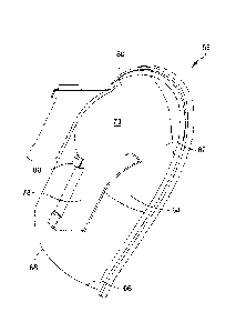
100471 Fig. II is a side view of the valve body and overflow tube of the
assembly of Fig. 10
showing the vent cover installed within the valve body of the assembly.
DETAILED DESCRIPTION OF 'FHE INVENTION
100481 A vent cover is described herein for use with various flush valve
assemblies,
particularly those useful for high efficiency and high performance toilets.
HET and HPI
compliant assemblies and valve bodies with high flush capacity can have issues
with a large
and generally streamlined flow of flush water entering the valve body and
being drawn in by
the valve body design, such as those with radiused inlets and the like. As a
result, the entrance
to the overflow tube and/or the vent tube of the valve assembly, which
typically is useful for
11
releasing upwardly mobile air trapped in the system, either in the valve body
prior to entrance
of flush water through the valve body from the toilet tank, or in the toilet
itself, can be blocked
by the incoming flush water.
[0049] The present vent cover addresses that issue and provides a simple
and inexpensive
solution to enhance performance of a toilet system including a toilet flush
valve. The vent
cover will be described in connection with one such HET valve design, a poppet
valve
assembly, however, it should be understood that the vent cover can be used
with a variety of
flush valve designs for improving performance.
[0050] As used herein, words such as "upper" and "lower," "interior" and
"exterior,"
"inner" and "outer," "top" and "bottom," and words of similar import are
intended to be used to
better understand the invention when explained with reference to directions in
the drawings
incorporated in this disclosure. They are for illustrative purposes only, are
intended to have
their ordinary meaning and import, and are not otherwise intended to be
limiting with respect to
the scope of the invention.
[0051] As shown in Figs. 1-5, an example of a flush valve assembly which
may include a
vent cover is shown. The flush valve assembly, generally referred to herein as
assembly 10
includes a valve body 12. The valve body as shown corresponds to that of U.S.
Patent No.
8,079,095. The valve
body 12 has an upper inlet end 14 having an inlet opening 16 therethrough. The
upper inlet end
is designed to receive fluid that enters into the flush valve body from a
water source, and
typically from within a toilet tank T as shown in Fig. 2. The valve body
further includes a
lower outlet end 18 which defines an outlet opening 20 therethrough. Flush
fluid, including
water, exits the flush valve body 12 through the outlet and typically would
pass into the inlet of
a toilet upon which tank T is installed. From there, fluid passes into a
various interior
geometries of a toilet bowl, which can be varied to include rim channels
and/or jet channels and
in most cases an initial manifold where incoming water is directed to various
channels and/or
openings in the bowl. After the flush cycle is over, that water is drawn from
the toilet bowl by
siphon through a trapway to a sewage outlet, and the flush valve is closed. A
filling valve F is
then triggered to re-fill the tank for the next flush cycle.
[0052] The valve body 12 has a valve body wall 22 that extends between the
upper inlet
end 14 and the lower outlet end 18. The wall has an interior surface 24 that
defines a flow path
FP that extends generally longitudinally through the valve body 12 from the
valve body inlet
12
Date Recue/Date Received 2020-05-27
CA 02900809 2015-08-10
WO 2014/127371 PCT/US2014/016961
opening 16 to its outlet opening 20. The outlet opening 20 is preferably of a
similar cross-
sectional configuration to the lower section of the valve body and as shown,
in this embodiment
is generally circular in cross-section. In a preferred embodiment of such a
valve body, the inner
diameter of the outlet is about 3.0 in. to about 3.5 in. such that flush valve
assembly 10 for use
in standard commercial toilet embodiments, however, the diameter of the valve
body at the inlet
and outlet may vary depending on the desired design.
100531 The valve body 12 in the valve assembly 10 is preferably opened
and closed by way
of a cover 26. The cover 26 is capable of opening and closing over the inlet
opening 14 of the
valve body 12. The cover 26 may be varied in design depending on the valve
body, and sized
to work with the valve body, including having a slightly larger size than a
standard flapper
cover if needed to adequately work from a buoyancy perspective and to close
properly on a
radiused inlet common in HET and HPT valve assemblies. The valve may also have
additional
features if desired, such as floats, extra cover features and the like.
100541 As noted above, the flush valve assembly 10 is preferably located
and installed in a
tank T of a toilet and communicates with a conventional fill valve F (see Fig.
2). Any suitable
tank design and fill valve may be used as are known in the art or to be
developed. When a flush
actuator, such as a handle or similar mechanism is pushed, a flush is
initiated and the flush
valve assembly will also be actuated. As shown in Fig. 2, a flush handle H is
in mechanical
cooperation, such as by pivoting, with a lever L having a chain C. 'The chain
(which could also
be a simple line) is connected to the cover 26. Other flush mechanisms
(electronic or manual)
may be used as well.
100551 Valve body 12 includes a movable poppet cover 26 or seal that
moves in a
reciprocating manner via a guide rod 28 of a length designed to work within a
particular size
valve body 12. As shown, the upper end 14 of the valve body 26 has a radiused
inlet 30. The
mechanism for reciprocating movement may include any feature 32 or features
that allow for
coaxial, reciprocating movement of a rod 28 or similar element within the
valve body for
facilitating opening, which in the embodiment shown involves lifting the cover
by depressing
the handle H to move the lever L, pull up on the chain C and raise the cover
26. Detailed
description of one such design may be found in U.S. Patent 8,079,095. In Figs.
1-5, a molded
web structure 34 having a central hole 36 for receiving the rod 28 is shown.
However, it should
be understood that the feature 32 can be varied to accomplish this purpose
within the scope of
the invention described herein.
13
CA 02900809 2015-08-10
WO 2014/127371 PCT/US2014/016961
100561 As shown, in addition to providing the valve body upper inlet end
14 with an
optional, but preferred, radiused inlet 30, the valve body may also include an
elevated base
section 38. In one embodiment, the radiused inlet 30 has a preferred outer
diameter (OD) of
about 5 in. An extension 40 may be provided to the valve body 12 that has an
opening 42
.. defined for receiving and/or fitting over or into an overflow tube 44. An
overflow tube 44 may
be any suitable overflow tube in the art. The overflow tube 44 has an inlet 46
which lies flush
with the interior surface 24 of the valve body 12 and/or extends inwardly into
the valve body 12
to some degree. While a standard overflow tube is shown herein, it will be
understood to those
skilled in the art, that the valve body in the assemblies herein may benefit
from the vent cover
described herein on either a standard overflow tube or any other venting tube
provided on the
valve body. For purposes of convenience, in this detailed description and
embodiment, as well
as in the below described alternative embodiment having a different valve body
design,
reference is made to an overflow tube, but such reference is not meant to be
limiting and is
intended to be also useful on other typical venting tubes provided on valve
bodies that may
become blocked for air release due to the nature of the flow (quantity, speed,
etc.) through the
valve body.
[00571 The elevated base section 38 may be provided to elevate the valve
body 12 relative
to the floor of the toilet tank T. Exterior threads 48 may be provided along
at least part of the
elevated base section 38 to help secure the valve assembly 10 to a tank T and
also to a toilet
bowl on installation via a plurality of threads and corresponding fastening
member 50 (e.g., a
nut) as is known in the art. A gasket or seal may also be used to ensure a
water-tight fit. it will
be understood based on the disclosure that other mechanisms for securing the
valve body may
be used, and this particular embodiment is only intended to be an example
embodiment and not
to limit how the valve body is connected to the tank and/or bowl. An optional
bracket 52 or
other fastening mechanism may also be used to further secure the valve body
using a screw 54
or the like if desired.
100581 The poppet cover 26 is coaxially and slidably mounted with respect
to the valve
body through feature 32. When the valve is open and the cover is lifted, the
inlet opening 16 to
the valve body 12 is in fluid communication with water from the tank T. it
moves from a first
rest position (see Fig. 2) upwardly. When open, in a second position the flush
is initiated and
the valve stays open until the cycle is complete.
14
CA 02900809 2015-08-10
WO 2014/127371 PCT/US2014/016961
[00591 When open, and upon elevation of the cover 26, buoyant forces and
fluid pressure
exerted on a bottom surface of the cover (which may include an optional seal
thereon) prompts
elevation of poppet cover 26 above inlet opening 16 of the valve body 12. When
the buoyant
force exceeds the hydrodynamic fluid force (e.g., the water level in tank T is
high and the fluid
"suction" on the poppet cover 26 is low prior to tank discharge), the poppet
cover 26 lifts above
a radiused inlet 30. Flush water can then flow into the inlet opening 16 and
proceed into the
valve body. The guide rod 28 remains in alignment with the hole 36 in the web
34 to ensure an
axial return path to the valve's closed position. Buoyant :forces and fluid
pressure in equilibrium
keep the poppet cover elevated for a time sufficient to empty the contents of
the tank and
initiate refilling thereof by filler valve F. As the tank volume discharges
through valve inlet
opening 16, the water level in tank I decreases and poppet cover 26 descends
toward the
radiused inlet 30. Increasing hydrodynamic forces acting upon the cover 26
counteract the
buoyant force to allow a generally rapid descent of the poppet cover 26 and
decrease the
available area to allow water to enter the valve until the initial valve rest
position is regained.
[00601 It is noted that the elevated base section 38, if provided to the
valve body, raises the
effective head level of the flush valve assembly 10. The elevated head reduces
the available
volume for tank discharge yet realizes improved discharge performance through
a discharge
outlet. The preferred embodiment shown of a poppet valve assembly combines a
radiused inlet
configuration with an elevated valve body such that the effective head is
approximately equal to
that used in conventional flush valves, when the radius of the radiused inlet
is preferably about
0.75 in. to about 1 in. This has the advantage also of reducing the available
maximum
discharge water volume, while realizing superior water discharge that uses the
entire outlet
diameter. The valve body wall 12 further preferably includes a slight tapering
along a profile
thereof such that the inner diameter thereof gradually decreases.
[00611 The overflow tube 44, has an inlet typically positioned within the
valve body flow
path FP or positioned so as to be flush with the interior surface 24 of the
valve body 12. The
inlet opening 46 is open to the interior of valve body and is in communication
with the flow
path FP within the valve body 12 so that backflow liquid due to blockage and
trapped air can
exit into the overflow tube. The overflow tube 44 also preferably has an
outlet opening 56 for
releasing air and/or fluid from within the overflow tube coming from the
interior of the valve
body 12. The configuration and size of the inlet to an overflow tube or
venting tube in a flush
valve may vary and it should be understood within the scope of the invention
that the vent
CA 02900809 2015-08-10
WO 2014/127371 PCT/US2014/016961
cover described herein can be varied also in configuration to accommodate such
inlet
variations.
[00621 The invention provides a vent cover 58 having a vent cover wall
60. The vent cover
wall 60 and vent cover are preferably formed as a unitary piece, however, it
is possible within
the scope of the invention that certain portions are separately formed and
molded or otherwise
joined together. The wall 60 of the vent cover 58 has with an upper portion
62, a body portion
64 and a lower portion 66. The lower portion 66 defines an inlet opening 68 to
the vent cover
58 for receiving air passing upwardly (arrow A) from within the valve body
flow path and/or
from a toilet through a toilet inlet (not shown). The vent cover wall 60
further has an exterior
.. surface 70 and an interior surface 72. The interior surface is configured
to define a vent cover
passage 74 for receiving air from the inlet opening of the vent cover 58. At
least the upper
portion 62 of the vent cover wall preferably contacts the interior surface 24
of the valve body
12 at a location Q or area above the inlet opening 46 of the overflow tube 44.
The passage 74 is
configured to allow air and/or water entering the vent cover 58 from the vent
cover inlet
opening 68 to pass upwardly through the vent cover passage 74 and then to exit
the vent cover
58 through the inlet opening 46 of the overflow tube 44. While the vent cover
58 can be
attached in only one area and/or pressure fit against the interior surface 24
of the valve body, it
is preferred that it be attached by way of the outer edge 76 of the vent cover
wall 60 extending
around the vent cover, at least around the upper portion 62 and the body
portion 64 of the vent
cover wall. The outer edge may be flush or have an extending portion as shown
for ease of'
attachment and stability against the interior surface 24 of the valve body. if
an extending edge
is used, it is not necessary to include it around the bottom. portion 66 with
the exception of
where it will abut the valve body wall.
100631 The outer edge 76 and the shape of the vent cover can vary and may
be shaped so as
to conform to the interior surface 24 of the valve body 12 if desired. The
vent cover wall
and/or the outer edge thereof is preferably configured to preferably contact
the interior surface
of a valve body at a location above an inlet of an overflow or other venting
tube on a valve
body when the vent cover is installed on a valve body, and preferably
optionally may also be
configured so that the entire outer edge 76 contacts the interior surface 24
of the valve body
with the exception of the bottom portion that is intended to be separated from
the interior
surface of the valve body so as to provide the passage 74.
16
CA 02900809 2015-08-10
WO 2014/127371 PCT/US2014/016961
100641 The vent cover may be formed of a variety of materials variety of
materials, such as,
for example, metals and metal alloys (e.g., copper, brass, nickel, lead,
titanium, stainless steel,
etc.) as well as polymeric or hard rubber materials (e.g., polystyrene-
butadiene-styrenes (SBS),
polyacrylonitrile-butadiene-styrenes (ABS)), polyamides (PA), polyimides (PO,
polyaryleries
(polyetherether ketone (PEEK), polyether ketone (PEK), polyether ketone ketone
(PEKK) and
the like), polyethylene sulfones (PES), polyetherimides (PEI),
polytetrafluoroethylene (PTFE),
fluoroplastics (FEP and PFA), olefmic rubbers, polyethylenes (PE),
polypropylenes (PP),
polyvinylchloride (PVC), polyoxyalkylenes (i.e., polyaeetals) (e.g.,
polyoxymethylenes (POM),
polyoxyethylenes (POE), polyoxybutylenes (P013), etc.), styrene-maleic-
anhydrides (SMA),
and other similar molding materials, composites, blends and/or copolymers of
these materials,
provided the materials provide adequate strength and resist deformation over
time in contact
with water under pressure. Composite materials may include fibrous and
particulate materials
such as glass fibers, carbon fibers, aramid fibers, Kevlart, mica, carbon
powder, and other
fillers known in the art. Similar materials to those noted above may also be
used to form
various parts of the valve body and cover.
100651 The vent cover wall 60 is preferably curved to accommodate upward
flowing air
and/or liquid in an amount adequate to alleviate negative impact of trapped
air while otherwise
minimizing any interference with the downward flow through the valve body
during a flush
cycle. Thus a curved design assists in avoiding turbulence and interruption to
a more laminar
flow pattern contributed to by the radiused inlet and/or tapered and/or
elevated valve body
design. it will be understood, however, based on this disclosure that a
variety of cross-sectional
configurations and wall designs could be used for varied effects or
manufacturing reasons,
including, for example, a conical configuration having a semi-circular cross-
section but larger
at the lower portion of the vent cover and narrowing to a small end at the
upper portion, a bent
plate configuration which has more of a rectangular or trapazoidal cross-
section and that may or
may not have varying widths along its length, and the like.
100661 As shown in the Figures, along the body portion 64, and below the
upper portion 62
of the vent cover wall and above the lower portion 66 of the vent cover wall
60 and above the
inlet opening 68, the vent cover wall has a generally semi-circular
configuration in transverse
.. cross-section and has a radius R associated therewith that is measured in
the transverse
direction across the vent cover 58. As shown in Fig. 1, a longitudinal axis L
runs through the
valve body 12. The radius R is measured in a direction perpendicular to such
axis and any
17
CA 02900809 2015-08-10
WO 2014/127371
PCT/US2014/016961
parallel longitudinal axis through the vent cover when installed. The passage
74 through the
vent cover 58 within the body portion 64 of the vent cover wall also has a
generally semi-
circular configuration. The radius R of the vent cover wall 58 is relatively
constant in the body
portion 64 of the vent cover wall with the exception that there may be
provided some gradual
tapering to meet the configuration of the valve body interior surface 24 if
desired, when the
vent cover 58 is installed, to prevent an escape of air by directing the air
by using a tighter seal
between the outer edge 76 of the vent cover wall 60 and the interior surface
24 of the valve
body 12. Thus the radius R. may be constant for a perpendicularly extending
valve body wall,
or, if desired, the outer edge 76 and body portion 64 slightly tapered to meet
the configuration
of the interior surface 24 of the valve body 12. As shown, the outer edge is
slightly tapered
such that the radius R would decrease from the upper portion 62 of the vent
cover wall 60
towards the lower portion 66 of the vent cover 58.
100671 It should be understood that in the embodiment shown, the general
concept
incorporates the facing outer edge of the vent cover wall and/or the overall
vent cover wall
structure conformed to work with and accommodate the shape of the interior
surface of the
valve body. Similarly, while the vent cover is shown in a semi-circular cross-
sectional
configuration, it should be understood that other shapes are contemplated and
are within the
scope of the invention, including a fully circular tube, a generally
elliptical shape or semi-
elliptical shape, a generally rectangular configuration, a generally
triangular configuration,
polygonal configuration, or the like. In selecting the optimal shape, the
interior surface of the
valve body to which the vent cover is to be attached or installed as well as
the flow
characteristics within that valve may be taken into account.
100681 In the embodiment shown, the outer edge 76 of the vent cover wall
60 preferably
extends along the upper portion 62 and the body portion 64 of the vent cover
wall 60, and the
upper portion 62 of vent cover wall is also preferably arcuately curved such
that the radius R of
the vent cover wall in the upper portion will decrease along the upper portion
of the vent cover
wall from the body portion of the vent cover wall towards the edge of the
upper portion of the
vent cover wall as it approaches connection to the interior surface of the
valve body at a
location above the inlet of the overflow tube. The outer edge 76 of the vent
cover wall 60 also
as shown is configured so as to meet the interior surface 24 of a valve body
12 of a flush valve
assembly 10 in facing engagement when the vent cover 58 is installed in a
flush valve assembly
10 although it need not be.
18
CA 02900809 2015-08-10
WO 2014/127371 PCT/US2014/016961
100691 The vent cover preferably has a length as measured parallel to a
longitudinal axis of
the vent cover. It need not be longer than necessary to cover an opening inlet
to an overflow or
venting tube in the valve body, but should preferably at least cover the inlet
of the overflow or
vent tube. Preferably, it extends for an additional length /below the bottom
77 of the inlet of
the overflow tube 44 or other vent tube. The length / may be varied for
optimal effects using
varying vent cover configurations and in various types of valve bodies. As
shown, the vent
cover has a length / as measured longitudinally from the bottom 77 of an inlet
46 of an
overflow tube 44 or venting tube inlet to lower portion 66 of the vent cover
body, i. e. , at the
vent cover inlet 68, of about 0 to about 100 mm below the bottom of an inlet
of an overflow
tube or venting tube, preferably about 10 mm to about 70 mm below the bottom
of an inlet of
an overflow or venting tube, and more preferably about 25 to about 65 mm below
the bottom of
the inlet of an overflow or venting tube.
100701 -The vent cover and the vent cover wall are preferably formed of
materials such as
those noted above. Where affixed to the interior surface of the valve body of
the flush valve
assembly, the vent cover may be attached by adhesive, ultrasonic welding
and/or polymeric
heat welding. in addition, the vent cover may be formed of a material that is
capable of being
heat molded to an interior surface of the valve body of a flush valve. The
vent cover may also
be integrally molded into a flush valve body.
100711 As shown, the vent cover may also be mounted within the valve body
not only by
molding or adhesive but through mechanical methods, including providing a
connector or other
aspect to the wall that assists in connecting it to the interior surface of
the valve body.
100721 As shown best in Fig. 3, projections 78 may be provided that
extend outwardly from
the exterior surface 70 of the vent cover wall 60 and which are configured for
engaging a
feature 82 of a valve body 12 by way of a hook or end piece 80 on the end of
the projections 78.
.. Alternatively or in addition, the projections could be made so as to engage
the interior surface
of the valve body of a flush valve upon installation of the vent cover such as
by providing a
hole or catch on the interior surface.
100731 Another embodiment of a flush valve assembly 110 herein is shown
to illustrate
installation of a vent cover 158 within a different design flush valve. As
shown in Figs. 10 and
11, the flush valve assembly 110 has a valve body 112 with a valve body wall
122 that includes
an upper inlet section 114, a base section 118 similar to a lower section in
the prior embodiment
for attaching to a toilet tank T via the tank floor. The valve body 112 may
flirther include an
19
extension section 184 situated between the inlet section 114 and the base
section 118. Such a
flush valve assembly may be seen in U.S. Patent No. 8,266,733.
In a preferred embodiment, at least one of an
interior surface 186 of the base section 118 and an interior surface 188 of
the extension section
184 is tapered. The valve body has a diameter D measured transversely across
the valve body.
The diameter D in a tapered design as shown would decrease linearly from an
upper end of
each section in a direction toward a lower end of each section as shown in
Fig. 11, wherein the
diameters are measured transversely across each section. However, it is also
within the scope
of the invention to use non-linear tapering as taught in U.S. 7,676,858.
[0074] The valve body 112 as shown is further an elevated valve body and
an HET or HPT
design. The upper inlet end 114 of the valve body further comprises a radiused
inlet 130 and it
is preferred that any tapered portion of the valve body wall 122 be below the
radiused inlet
portion 130.
[0075] The valve body wall 122 as shown comprises an upper inlet section
having a height
shown as Ri, a base section having a height shown as B for attaching to a
toilet tank floor, and
an extension section having a height E situated between the inlet section and
the base section.
[0076] The radiused inlet portion 114 has a curved arcuate profile and
radiused inlet 130
which in a longitudinal cross section, for example as shown in Fig. 11,
preferably forms a
circular segment having a radius R2 which can be measured under the curved
surface of the
radiused inlet 130. The radiused inlet allows water flowing into the valve
body in curves over
the radiused inlet 130 into the valve body 112. It also provides a larger
inlet area on the upper
inlet end 114 of the valve body 112. The radius R2 of the radiused inlet 130
may be varied
from about 1/8 inch to about 1 inch, but is preferably about 1/8 inch to about
3/8 inch, and most
preferably about 3/8 inch when the diameter of the lower outlet end 22 is
about 2 inches.
[0077] The valve body has a wall 122 that extends between the upper
inlet end 114 to the
lower outlet end 118 but at the very bottom of the valve body 112. The ends
are preferably
situated so that upon installation the upper inlet end 114 is located in a
tank T of a toilet and the
lowermost portion of the base section B or lower end 118 is located below the
tank T floor as
shown. In cross-sectional configuration, the inlet of the valve body has a
generally circular
shape, which means a curved configuration such as a circle, oval, elliptical
or egg-shaped
configuration, but is preferably circular. The wall 122 may be an integrally
formed wall such
Date Recue/Date Received 2020-05-27
CA 02900809 2015-08-10
WO 2014/127371
PCT/US2014/016961
as to form a unitary structure valve body or may be formed of segments as
discussed herein. It
should also be understood that the certain segments of the wall may be
integrally formed
together while others can be made to be detachably connected. The segments of
the wall body
may thus be molded together, formed as separate piece(s) and fused or
detachably connected to
one another, such as by chamfering (described elsewhere herein with respect to
the radiused
inlet), snap-lock edge fittings, detents, screws, bolts, interlocking snap-fit
pieces, connectors,
and the like. Any suitable connection mechanism for adjoining the pieces may
be used,
provided the pieces form a tight fit and are leak-resistant. To assist in
being leak-resistant, if
separate pieces are joined together through mechanical mechanisms, such as
screws, fittings,
connectors and the like, it is preferred that a sealing member is placed
between adjoining
pieces. Sealing members may be, for example, standard elastomeric or plastic 0-
ring(s) or
gasket(s) suitable for plumbing use. Such sealing members are optional if the
pieces form a
leak-tight fit and are not needed if the pieces are fused or molded together.
100781 The wall has an interior surface 124 extending the length of the
valve body wall that
defines the flow path FP'. The flow path FP' takes the shape of the interior
surface of the body
wall and extends through the entire inner space of the valve body so as to
create a flow path
profile when viewed in longitudinal cross section through the valve body. The
flow path FP'
also has a generally circular transverse cross section along the valve body,
however, as
explained above, the diameter D of the cross section can. vary over the length
of the flow path.
As used herein, "diameter" means the longest measure across the generally
circular cross
section in a transverse direction.
100791 The valve body 112 is preferably an elevated valve body. The
height h measured
longitudinally along the valve body 112 is greater than the largest diameter D
of the transverse
cross-section of the flow path (in this case measured at the radiused inlet
130). This
configuration allows for installation of the valve body in the toilet tank so
as to provide for an
elevated valve body portion lying above the toilet tank floor T. This
configuration raises the
flow rate through the valve body over standard valve bodies and creates more
dynamic flow
through the valve body while achieving the same head (distance from the upper
surface of the
tank water to the "choke" point or point of construction of the valve body).
100801 The precise height h of the valve body may be varied, but it is
preferred that the
height h is sufficient so that the length of the valve body above the tank
floor T is larger than a
standard low profile valve body and preferably approximates or is greater than
the largest
21
diameter D. The height h is preferably greater than about 2.8 inch and can be
as much as about
5.2 inches, and more preferably is about 3.5 inches to about 4.1 inches. The
diameter D is
greater than about 2.0 inches, and preferably is about 2.25 inches to about
3.5 inches, more
preferably about 2.4 inches to about 3.3 inches and most preferably about 3.2
inches to about
3.25 inches. The ratio of the height h to the diameter d is preferably about
2.3 to about 0.8 and
more preferably about 1.7 to about 1.1.
[0081] The valve assembly 110 further includes a valve cover 126 as
shown in Fig. 10,
which is preferably a flapper valve cover, but may be an modified flapper
cover as described in
U.S. Patent No. 8,266,733, and is preferably sufficiently
large so as to cover the inlet opening 130 for closing the valve body and
preferably is slightly
larger so as to contact and close across the radiused inlet.
[0082] A sealing ring 190 may also be provided as is known in the art to
seat the valve
body 112 against the opening in the tank T in the floor thereof. The outer
surface 192 of the
valve body 112 along the base portion 118 is preferably threaded so as to have
threads 194 for
receiving a locking connection ring or similar device for securing the seal
against the tank.
While a ring, threaded end and locking connector are shown in Fig. 10 and 11,
it should be
understood based on the disclosure that other locking and sealing mechanisms
may be used
within the scope of the invention.
[0083] Thus, the vent cover 10, 110 herein can be slightly modified in
shape or
configuration to conform to various HET and HPT valve body designs, including
those
highlighted herein, but also others in existence or to be provided. It has a
minimal impact on
the flow path while providing the benefit of substantially diverting the flow
of water that may
block the overflow tube and/or allowing a release path for trapped air in the
system that
otherwise may be blocked from exiting through the overflow tube inlet or a
venting tube inlet
due to the high flow of water through the valve body under such advanced valve
body designs
incorporating features like a 360 inlet path as in a poppet valve, radiused
inlets and/or elevated
valve bodies.
[0084] The invention will now be described with reference to the
following non-limiting
Example:
22
Date Recue/Date Received 2020-05-27
CA 02900809 2015-08-10
WO 2014/127371 PCT/US2014/016961
EXAMPLE
100851 Tests were conducted using various vent scoops having a
configuration as shown in
Fig. 6 but having a varying length as measured below the overflow scoop. The
scoops were
installed in the standard flush valve of 4.8 liflush toilet, an American
Standard Champion
Max toilet having a model 4215 tank and a model 3195a bowl. Average peak
flush rate (Us)
and average time(s) to 2,500 cm3/s (2,500 ml/s) data were measured for each of
four sample
toilets, each of which was flushed four times, using the 4.8 1 flush capacity.
The time to 2,500
ras or greater is the time it takes from initiation of the flush cycle to
reach an instantaneous
flow rate from the outlet of the bowl that is 2,500 ml/s or more. A peak flow
curve was
generated through testing in which a toilet bowl was set on a flush stand. The
bowl was set to
the desired water consumption and water pressure. A Toledo Speedweight scale
was placed
under the bowl. A bucket was placed on the scale. The distance form the bowl
outlet to the
standard bucket (having 12 inch diameter) was set to 17 inches. The scale
logged data at a rate
of 25 data points per second. The Toledo scale was connected to a data
logging system. The
bowl was flushed to gather the data. The time to peak rate was measured from
the first data
point to where the peak value was achieved in. the flow curve data. The time
to 2,500 mils was
also determined from the gathered data.
[00861 The average for these parameters and their standard deviation are
reported in Table
1 below. Comparative Sample 1 has no vent cover. Inventive Sample 1 had a vent
cover
having the configuration as shown in Fig. 6 installed in the same valve body.
In the sample, the
vent cover had a length as measured longitudinally from the center of the
overflow tube inlet
opening (the inlet having a diameter of 30 mm) to the bottom of the vent
cover, i.e., at the inlet
opening of the vent cover of 85 mm (65 mm. from the bottom of the overflow
inlet opening).
Inventive Sample 2 used a vent cover as shown in Fig. 6 but with a length
measured
longitudinally from the center of the inlet opening of the overflow tube to
the bottom inlet end
of the installed vent cover of 40 mm (25 mm from. the bottom of the overflow
tube inlet). The
test data in Table I show an improvement in hydraulic performance and a faster
flush. The data
in this Example demonstrate a reduction in the variability in time to peak or
time to 2,500 mlis
(i.e., a lower standard deviation). The mixing of air and water during the
milliseconds of a
flush is chaotic. Air may or may not find a path to escape. When it cannot
escape, it blocks the
efficient flow of water and there is a delay in time to peak. Addition of the
vent scoop reduces
23
CA 02900809 2015-08-10
WO 2014/127371
PCT/US2014/016961
the probability of this occurrence, and thus, the data shows a lower standard
deviation in time to
peak or time to 2,500 His. The average time to peak or to 2,500 ml/s across
multiple bowls
and flush cycles may thus be reduced because the occasions of delayed times to
peak flush
cycles are reduced or eliminated.
TABLE l
Vent Sample Peak Rate Time to
2,500 em3is
(Vs) (s)
Comp. Sample I - average 3.55 0.48 ..
Comp. Sample I - std. deviation 0.44 0.23
Inv. Sample I - average 3.54 0.36
Inv. Sample 1 - std. deviation 0.31 0.05
Inv. Sample 2 - average 3.54 0.32
Inv..Sam_ple 2 - std, deviation
[00871 It will be
appreciated by those skilled in the art that changes could be made to the
embodiments described above without departing from the broad inventive concept
thereof. It is
understood, therefore, that this invention is not limited to the particular
embodiments disclosed,
but it is intended to cover modifications within the spirit and scope of the
present invention as
defined by the appended claims.
24