Note: Descriptions are shown in the official language in which they were submitted.
H-7688-1-CA
MOLDING SYSTEM HAVING AN ADJUSTABLE MOLD SHUT HEIGHT
FIELD OF THE INVENTION
[0001] The present invention generally relates to, but is not limited to,
molding systems, and
more specifically the present invention relates to, but is not limited to,
molding systems having
an adjustable mold shut height.
BACKGROUND OF THE INVENTION
[0002] Molding is a process by virtue of which a molded article can be formed
from molding
material by using a molding system. Various molded articles can be formed by
using the
molding process, such as an injection molding process. One example of a molded
article that can
be formed, for example, from Polyethylene Terephthalate (PET) material is a
preform that is
capable of being subsequently blown into a beverage container, such as, a
bottle and thc like.
[0003] As an illustration, injection molding of PET material involves heating
the molding
material (ex. PET pellets, etc.) to a homogeneous molten state and injecting,
under pressure, the
so-melted PET material into a molding cavity defined, at least in part, by a
female cavity piece
and a male core piece mounted respectively on a cavity plate and a core plate
of the mold. The
cavity plate and the core plate are urged together and are held together by
clamp force, the clamp
force being sufficient enough to keep the cavity and the core pieces together
against the pressure
of the injected PET material. The molding cavity has a shape that
substantially corresponds to a
final cold-state shape of the molded article to be molded. The so-injected PET
material is then
cooled to a temperature sufficient to enable ejection of the so-formed molded
article from the
mold. When cooled, the molded article shrinks inside of the molding cavity
and, as such, when
the cavity and core plates are urged apart, the molded article tends to remain
associated with the
core piece. Accordingly, by urging the core plate away from the cavity plate,
the molded article
can be demolded, i.e. ejected off of the core piece. Ejection structures are
known to assist in
removing the molded articles from the core halves. Examples of the ejection
structures include
stripper plates, ejector pins, etc.
[0004] When dealing with molding a preform that is capable of being blown into
a beverage
container, one consideration that needs to be addressed is forming a so-called
"neck portion".
Typically and as an example, the neck portion includes (i) threads (or other
suitable structure)
for accepting and retaining a closure assembly (ex. a bottle cap), and (ii) an
anti-pilferage
assembly configured to cooperate, for example, with the closure assembly to
indicate whether
the end product (i.e. the beverage container that has been filled with a
beverage and shipped to a
store) has been tampered with in any way. The neck portion may comprise other
additional
1
CA 2901398 2017-06-28
1-1-7688-1-CA
elements used for various purposes, for example, to cooperate with parts of
the molding system
(ex. a support ledge, etc.). As is appreciated in the art, the neck portion
can not be easily formed
by using the cavity and core halves. Traditionally, split mold inserts
(sometimes referred to by
those skilled in the art as "neck rings") have been used to form the neck
portion.
[0005] With reference to Figure 1, a section along a portion of an injection
mold 50 illustrates a
portion of typical molding insert stack assembly 60 that is arranged within a
molding system
(not depicted). The description of Figure 1 that will be presented herein
below will be greatly
simplified, as it is expected that one skilled in the art will appreciate
general configuration of
other components of the injection mold 50 that will not be discussed in the
following
description.
[0006] The molding insert stack assembly 60 includes a neck ring insert pair
52 that together
with a mold cavity insert 54, a gate insert (not shown) and a core insert 61
define a molding
cavity (not separately numbered) where molding material can be injected to
form a molded
article, such as a preform 63. In order to facilitate forming of the neck
portion of the preform 63
and subsequent removal of the preform 63, the neck ring insert pair 52
comprises a pair of
complementary neck ring inserts that are mounted on adjacent slides of a slide
pair 68. The slide
pair 68 is slidably mounted on a top surface of a stripper plate 66. As
commonly known, and as,
for example, generally described in United States patent 6,799,962 to Mai et
al (granted on
October 5, 2004), the stripper plate 66 is configured to be movable relative
to a cavity plate
assembly 74 and a core plate assembly (not depicted), when the mold is
arranged in an open
configuration, whereby the slide pair 68, and the complementary neck ring
insert pair 52
mounted thereon, can be laterally driven, via a cam arrangement or some other
means (not
shown), for the release of the molded article from the molding cavity.
[0007] A typical neck ring insert has a body that includes a pair of
projecting portions 70 that
extend from a top and a bottom face of a flange portion 72 (i.e. a top
projecting portion and a
bottom projecting portion). Typically, the bottom face of the flange portion
72 abuts, in use, a
top surface of the slide pair 68. Even though not depicted in Figure 1, one
skilled in the art will
appreciate that the neck ring insert pair 52 cooperates with suitable
fasteners for connecting to a
respective one of the slide pair 68. In use, during certain portions of a
molding cycle, the top
projecting portion cooperates with a female receptacle disposed on the cavity
plate assembly 74.
SUMMARY OF THE INVENTION
[0008] According to a broad aspect of the invention there is provided an
injection mold
comprising a first mold half and a second mold half. The first and second mold
halves are
supported and movable relative to each other, and the first and second mold
halves have a mold
2
CA 2901398 2017-06-28
H-7688-1-CA
shut height when said mold is an operational configuration. The mold also
comprises a mold
shut height adjustment apparatus operable to provide for a change in the mold
shut height,
wherein the mold shut height adjustment mechanism further comprises a neck
ring adjustment
mechanism operable for adjusting a configuration of neck ring devices of the
injection mold.
[0009] According to another broad aspect of the invention there is provided a
method of
operating an injection mold comprising: (i) operating the mold in a first
operational
configuration; (ii) varying a mold shut height of the mold; and (iii)
operating the mold in a
second operational configuration; wherein varying the mold shut height of the
mold includes
adjusting a configuration of neck ring devices of the injection mold.
[0010] These and other aspects and features of non-limiting embodiments of the
present
invention will now become apparent to those skilled in the art upon review of
the following
description of specific non-limiting embodiments of the invention in
conjunction with the
accompanying drawings.
DESCRIPTION OF THE DRAWINGS
[0011] A better understanding of the embodiments of the present invention
(including
alternatives and/or variations thereof) may be obtained with reference to the
detailed description
of the non-limiting embodiments along with the following drawings, in which:
[0012] Figure 1 depicts a cross-section along an operational axis of a molding
stack
implemented in accordance with known techniques;
[0013] Figure 2 is a cross-sectional view through part of a mold;
[0014] Figure 2A is an enlarged view of the representative portion that is
marked as 2A in
Figure 2 including one representative mold stack;
[0015] Figure 3 is an isometric view of a core plate of the mold of Figure 2;
[0016] Figure 4A is a front elevation view of the core plate of Figure 3;
[0017] Figures 4B and 4C are cross-sectional views of the core plate of Figure
4A, along
sections 4B-4B and 4C-4C, respectively;
[0018] Figure 4D is an enlarged view of the cross-section shown in Figure 4C;
[0019] Figure 4E is an enlarged view of the cross-section shown in Figure 4B;
[0020] Figure 4F is an enlarged view of the portion 4F in Figure 4E, with a
further enlarged
portion thereof;
[0021] Figure 4G is an enlarged view of the portion 4G in Figure 4E;
[0022] Figure 4H is a view of part of the portion 4F in Figure 4E shown in a
retracted position,
with a portion of a stripper plate of the mold;
3
CA 2901398 2017-06-28
H-7688-1-CA
[0023] Figure 41 is a view of the part of Figure 4H but shown in an extended
position, with a
portion of a stripper plate of the mold;
[0024] Figure 5 is an isometric view of a sub-assembly of the injection mold
part of Figure 2;
[0025] Figure 6 is an isometric view of another sub-assembly of the injection
mold part of
Figure 2;
[0026] Figure 7 is an isometric view of another sub-assembly of the mold part
of Figure 2;
[0027] Figure 8A is an isometric view of another sub-assembly of the mold part
of Figure 2
[0028] Figures. 8B-8C are enlarged views of portions marked 8B, 8C,
respectively, of the sub-
assembly of Figure 8A;
[0029] Figure 8D is a cross-sectional view at section 8D-8D in Figure 4A;
[0030] Figure 8E is an enlarged view of portion marked 8E in Figure 8D;
[0031] Figure 8F is a top plan view of the portion marked 8B in Figure 8A in
one operational
position;
[0032] Figure 8G is a top plan view of the portion in Figure 8F but in another
operational
position;
[0033] Figure 9A is a front elevation view of a stripper plate of the mold of
Figure 2, mounted
on the core plate of Figure 3;
[0034] Figure 9B is a cross-sectional view of the stripper plate and core
plate of Figure 9A at
section 9B-9B in Figure 9A.
[0035] Figure 9C is an enlarged view of the cross-section shown in Figure 913;
[0036] Figure 9D is an enlarged view of the portion marked 9D in Figure 9C;
[0037] Figure 10 is an isometric view of a cavity plate of the mold part of
Figure. 2;
[0038] Figure 11A is a front elevation view of the cavity plate of Figure 10;
[0039] Figure 11B is a cross-sectional view of the cavity plate of Figure 11A
at section 11B-
11B in Figure 11A;
[0040] Figure 11C is an enlarged view of the cross-section shown in Figure
11B;
[0041] Figure 12 is an enlarged view of the portion marked 12 in Figure 11C;
[0042] Figure 13 is an exploded view of a part shown in Figure 12;
[0043] Figure 14A is enlarged view of the portion marked 14 in Figure 11C in
one operational
position;
[0044] Figure 14B is an enlarged view of the portion marked 26 shown in Figure
11C but in
another operational position;
[0045] Figure 15 is a cross-sectional view through part of the mold part of
Figure 2, with the
injection mold open; and
4
CA 2901398 2017-06-28
H-7688-1-CA
[0046] Figure 16 is a cross-sectional view through part of the mold part of
Figure 2 with the
injection mold in an alternate configuration.
[0047] The drawings are not necessarily to scale and are may be illustrated by
phantom lines,
diagrammatic representations and fragmentary views. In certain instances,
details that are not
necessary for an understanding of the non-limiting embodiments or that render
other details
difficult to perceive may have been omitted.
DETAILED DESCRIPTION OF EMBODIMENTS
[0048] With reference to Figures 2 and 2A, another embodiment is illustrated
which includes a
distance augmenting structure for selectively controlling a shut height of a
mold. Figure 2 is a
cross-sectional view through an injection mold 1100 forming part of an
injection mold machine
(not shown). Figure 2A is an enlarged view of the portion marked 14A in Figure
2. As will be
explained hereinafter, the configuration of mold 1100 can be adjusted such
that it is configured
in a first normal operating mode or in a second alternate operational mode. In
the first
operational mode, mold 1100 may be configured for performing a normal molding
operation
such as, for example, molding of molded articles (not shown). In the second
operational mode,
mold 1100 may be configured for performing a molding operation such as, for
example, vent
cleaning as will be more fully explained hereafter. Alternatively, the second
mode may enable
the injection mold 1100 to operate in another operational mode other than the
normal operating
mode or a vent cleaning mode.
[0049] Generally, mold 1100 may be part of an injection mold machine (not
shown) and mold
1110 may include a first mold half generally designated 1222 and a second mold
half generally
designated 1223. First mold half 1222 may include a core plate 1103 and a
stripper plate 1117,
and second mold half 1223 may comprise a cavity plate 1110. The core plate
1103, stripper plate
1117, and cavity plate 1110 may all be appropriately supported on and movable
relative to each
other on a support frame (not shown) for normal operation of such a mold 1100,
in any suitable
manner as is well known in the art. A plurality of mold stacks 1111 may also
be provided. The
mold stacks 1111 may have components arranged in a stack configuration,
including
components installed in cavities 1191 which extend through the core plate
1103, stripper plate
1117 and wear plate 1119, and cavities 1193, which extend through the cavity
plate 1110. All
mold stacks 1111 in mold 1100 may be formed in an identical manner or in a
substantially
identical manner. Alternatively, in other embodiments more than one
configuration of mold
stack may be provided in the same mold.
[0050] It should be noted that while in many, if not most, operational molds
like mold 1100 the
orientation would be such that axis X would be oriented generally horizontally
and
5
CA 2901398 2017-06-28
H-7688-1-CA
longitudinally in space, axis Y horizontally and transversely in space, and
axis Z vertically in
space, these orientations are not necessary. Mutually orthogonal axes X, Y and
Z may in other
embodiments be arranged in other spatial orientations.
[00511 Figure 2 shows the mold 1100 in a standard operating configuration with
the mold in a
closed position ready for injection of molding material such as a plastic into
the mold and thus
into the plurality of mold stacks 1111 to make production preforms. In Figure
2, there is
illustrated the distance (or height) H in a direction parallel to the X axis
between the outward
facing surface 1143 of core plate 1103 and the inward facing surface 2143 of
the cavity plate
1110. In the injection molding industry, the distance S in a direction
parallel to the X axis, as
illustrated in Figure 2, between the rear surface 1145 of core plate 1103 and
the forward facing
front surface 2145 of cavity plate 1110 is typically referred to as the mold
shut height. It will be
appreciated that as the height H changes, there is a corresponding change in
the mold shut height
S. In the first standard operating mode the height H will have a value H1
whereas in a second
operating mode the height H will have a value H2 that will be different, and
typically greater,
than value H1. Thus, when the mold 1100 alternates between configurations
corresponding to
the first operating mode and the second operating mode, the height H will vary
between H1 and
H2 and their will be a corresponding change in the shut height S from S1 to
S2.
[0052] Continuing with reference to Figures 2 and 2A, each mold stack 1111 may
include a
mold core 1102 fitted into the core plate 1103 and retained therein by a lock
ring 1104. Bolts
1105 may fixedly secure the lock ring 1104 to core plate 1103. The position of
lock ring 1104
relative to core plate 1103 remains fixed in the configurations corresponding
to the first and
second operating modes. The mold corc 1102 may contain a cooling tube 1106 for
the
transmission of cooling fluid from a source within the core plate 1103 to
remove heat from the
injected material in the mold cavity 1107 and solidify the molded part in the
mold cavity 1107.
[0053] Each mold stack 1111 may also include a cavity insert 1120 and an
adjacent gate insert
1129 that are retained in the cavity plate 1110 by a cavity flange 1131. Bolts
(not shown) may
secure the cavity flange 1131 to the cavity plate 1110. Thus, cavity flange
1131 can be fixed
relative to cavity plate 1100 and so there will be no relative movement of the
cavity plate 1110
and the cavity flange 1131 as the mold 1100 is alternated between
configurations for the first and
second operational modes referenced above. Cooling channels 1112 may circulate
cooling fluid
from a source through the cavity insert 1120 and gate insert 1129 to remove
heat from the
injected material.
[0054] The mold 1100 may also include one or more pairs of slide bars 1115a
and 111511 that
may be slidably supported on a wear plate 1119. Wear plate 1119 of mold 1100
may comprise a
single integrally formed piece of material with apertures formed therein, or
separate sections or
6
CA 2901398 2017-06-28
H-7688-1-CA
segments, and provide support material for slide bars 1115a, 1115b between the
slide bars and
the stripper plate 1117. The wear plate 1119 may thus be mounted on the
stripper plate 1117.
The apertures in the wear plate 1119 may be configured to at receive at least
part of regular
tonnage blocks 1118 and adaptive tonnage blocks 1113 extending from cavity
place 1110 so that
they are able to bear directly against the outward facing surface of stripper
plate 1117, rather
than bear against the wear plate 1119.
[0055] The slide bars 1115a, 1115b can be configured for carrying a pair of
neck ring halves
1114a and 1114b forming a neck ring associated with each mold stack 1111. The
multiple neck
ring halves 1114a, 1114b may commonly be fixedly attached such as with bolts
(not shown) to
respective slide bars 1115a, 1115b. The neck ring halves 1114a, 1114b can
slide with slide bars
1115a, 1115b respectively between an in-mold first position which corresponds
to a "standard
molding configuration" and an out-mold second position where the neck ring
halves are
withdrawn sufficiently to allow the ejection process to take place so that an
injected preform can
be removed from the mold cavity 1107. Neck ring halves 1114a, 1114b, can be
assembled onto
and connected to respective slide bars 1115a, 1115b and this assembly can be
moved by
connecting bars (such as connecting bars 4030a, 4030b as shown in Figure 6).
Connecting bars
can include a cam follower (such as rollers 4033 as shown in Figure 6). These
cam followers can
be inserted into a cam track defined in a cam (not shown). Any forward
(ejection) movement of
stripper plate assembly activates a connecting bar movement. Further details
of an example of
such an arrangement can be found in Applicant's US published patent
application, publication
no. US-2008/0241309-A1 for a Cam System For A Mold published October 2008.
However,
also as known in the art, movement of slide bars 1115a, 1115b and their
respective neck ring
halves 1114a, 1114b can be effected by mechanisms other than a cam track and
roller. By way
of example only, in other embodiments, an assembly incorporating a linear
actuator might be
employed. In this regard, Applicant's patent published US published patent
application no.
US2007/0059395 published March 15, 2007 discloses an example of such an
alternative
mechanism.
[0056] The neck ring halves 1114a, 1114b, like neck ring 300, also have at
least one additional
position and possibly more than one other position that may correspond with
one or more other
additional operational modes. For example, as illustrated, neck ring halves
1114a, 1114b may
have a third position which corresponds to another operational mode such as a
"vent cleaning
mode" configuration in which the neck ring halves may have moved outwardly a
relatively small
distance. As will be explained hereinafter, in mold 1100, the height H between
the cavity plate
1100 and the core plate 1103 (and thus the corresponding mold shut height S)
can be adjusted to
7
CA 2901398 2017-06-28
H-7688-1-CA
increase and decrease the height H and corresponding mold shut height and
thereby enable the
ring halves 1114a, 1114b to move between the standard mold operational
configuration and a
second operational configuration such as the vent cleaning mode configuration.
[0057] The wear plate 1119 is sacrificial material and reduces the wear on the
stripper plate
1117 due to movement of the neck ring halves 1114a, 1114b by the slide bars
1115a, 1115b each
time a molded part is released from the mold cavity 1107 and each time the
slide bars and neck
ring halves move between the first and second operational mode configurations.
Cooling
channels 1018 may be provided to circulate cooling fluid from a source through
the neck ring
halves 1114a and 1114b to remove heat from the injected material. Molten mold
material may be
conveyed to the mold cavity via a hot runner nozzle, hot runner manifold and
hot runner stacks
in a conventional manner known in the art.
[0058] It will be appreciated that when the plastic material is injected under
pressure into the
mold cavity 1107, outward pressure will be exerted upon the neck ring halves
1114a, 1114b. To
resist this force associated with the injected plastic, a clamping
(compressive) force A may be
applied to the mold stack 1111 to retain the mold stack 1111 in an appropriate
operational
configuration, either during standard molding operation or during an alternate
operation such as
vent cleaning. It will be appreciated that applying a compressive load A
causes reaction forces
throughout the mold stack 1111. Thus, due to the inclined mating surfaces
between cavity flange
1131 and neck ring halves 1114a, 1114b, a compressive force will act on neck
ring halves
1114a, 1114b along the longitudinal (X) and transverse (Y) axes, urging the
neck ring halves
1114a, 1114b, transversely inwards. In this way, by application of a suitable
compression force,
the relative positions of the neck ring halves 1114a, 1114b can be held at
either the desired
standard molding configuration or the vent cleaning configuration, which can
be determined by
the selection of the appropriate mold shut height S.
[0059] With the application of clamping force A to the mold stack 1111, little
if any of this load
will typically be carried through the slide bars 1115a, 1115b or wear plate
1119 or stripper plate
1117. In the normal operating configuration, additional load may be provided
to compress the
core plate 1103 and the cavity plate 1110 together and load may be transmitted
also from the
cavity plate 1110, through regular tonnage blocks 1118 (Figure 2 and 2A) into
the stripper plate
1117 and to the core plate 1103. In a second operational configuration, such
as a vent cleaning
mode, the stack 1111 may be in an "open" configuration with substantially no
compressive load
being transmitted through the stack 1111. A compressive load may however still
be provided to
compress the core plate and the cavity plate together and may be transmitted
also from the cavity
plate 1110, through adaptive tonnage blocks 1113 (Figure 2 and 2A) into the
stripper plate 1117
and to the core plate 1103 as will be described further below.
8
CA 2901398 2017-06-23
H-7688-1-CA
[0060] When the mold 1100 is in the standard operating configuration, the
clamping force A
being applied to the stack may be greater than the minimum load which would be
required to
resist injection pressure and hold the mold stack components in position.
Additional compressive
loading provides safety in case of processing or melt quality fluctuations
which would result in
preform flash during normal operation. Thus, the conventional or regular
tonnage blocks 1118
may bear additional load in co-operation with cavity plate 1110, stripper
plate 1117 and core
plate 1103. The height of the regular tonnage blocks can be selected to
provide an appropriate /
desired distance between the cavity plate 1110 and the stripper plate 1117.
Thus, in most normal
operating configurations, the tonnage blocks 1118 are positioned between and
space the cavity
plate 1110 and stripper plate 1117, and thus provide a height H and shut
height S of distances
required for the standard operational configuration for producing performs. As
noted above,
regular tonnage blocks 1118 are received in apertures in the wear plate 1119,
so that load borne
by the regular tonnage blocks 1118 is transferred to the stripper plate 1117.
It would only be in
an exceptional situation where a wear plate 1119 would be used to transmit
compressive loads
between the cavity plate and the core plate with the tonnage blocks engaging
the wear plate.
[0061] As will be described further below, adaptive tonnage blocks 1113 may
also be provided
and the position of the engaging surface of the adaptive tonnage blocks can he
selected to
provide an increased distance between the cavity plate 1110 and the stripper
plate 1117
providing a height H (and corresponding shut height S) of a distance required
for the alternate
operational configuration.
[0062] Mold 1100 may be provided with a mold shut height adjustment apparatus
that may
comprise one or more distance augmenting structures. In particular, the mold
shut height
adjustment apparatus may comprise one or more of three separate mechanisms to
cause an
adjustment of the height H (and thus also an adjustment of the mold shut
height S) and/or an
adjustment of thc configuration of the neck ring halves between the standard
molding
configuration and a second operational mode configuration such as the vent
cleaning
configuration. The mold shut height adjustment mechanisms may be integrated
and at least
partially embedded within one or both of the mold halves 1222, 1223. Three
such mechanisms
can be characterized as: (1) a cavity plate adjustment mechanism 2000; (2) a
neck ring
adjustment mechanism 4000; and (3) a core plate adjustment mechanism 3000. Of
these, the
cavity plate adjustment mechanism 2000 and core plate adjustment mechanism
3000 may cause
an adjustment of mold shut height, and this may indirectly during operation
result in an
adjustment of the configuration of the neck ring halves 1114a, 1114b.
[0063] With respect to core plate adjustment mechanism 3000, its function is
to adjust the
distance between core plate 1103 and stripper plate 1117. By increasing the
space between the
9
CA 2901398 2017-06-28
1-1-7688-1-CA
core plate 1103 and stripper plate 1117, the position of lock ring 1104
relative to neck ring
halves 1114a, 1114b can be adjusted. Specifically, the neck ring halves 1114a,
1114b can move
longitudinally away from lock ring 1104. As will be described later, a
corresponding adjustment
of a distance between cavity plate 1110 relative to stripper plate 1117 can
allow cavity flange
1131 to move (longitudinally) relative to the inclined surface of the neck
ring halves 1114a,
1114b. This movement can be facilitated by cavity plate adjustment mechanism
2000, to allow
neck ring halves 1114a, 1114b to move outwardly from the standard molding
configuration to a
vent cleaning configuration as described above.
[0064] With particular reference to Figures 3, 4 and 4A to 41, core plate
adjustment mechanism
3000 comprises a plurality of core plate adjustment devices 3001 that may be
referred to herein
as back up pads. The back up pads 3001 may be received in recesses or
apertures 3016 defined
in the core plate 1103. As is best shown in Figure 16, and as will be more
fully described
hereinafter, in an alternate operational configuration, the back up pads 3001
may be extended to
space stripper plate 1117 apart from core plate 1103. Accordingly, the
plurality of back up pads
3001 may be spaced in appropriate locations about core plate 1103 to provide
for a proper or
appropriate loading distribution between the core plate and stripper plate
1117 when the back up
pads 3001 are engaged to provide a separation of the core plate 1103 from the
stripper plate
1117 (the stripper plate not being shown in Figure 3 and Figures 4A-4G).
[0065] As is best shown in Figures 3 and 4F, each back up pad 3001 may
integrated within and
be partially embedded in core plate 1103. Each back up pad 3001 may include an
engagement
portion 3008 having an engagement surface 3023. Engagement portion 3008 is
moveable in a
direction parallel to axis X from a first, retracted position where the
engagement surface 3023 is
generally flush with, or reset behind, the surface 1143 of the core plate 1103
to a second,
extended position where the engagement surface 3023 extends past surface 1143
of core plate
1103. When the engagement surface 3023 is at the first (retracted) position
generally flush with,
or reset behind, surface 1143 of the core plate 1103, the mold 1100 may be in
its standard mold
operating configuration. When the engagement surface is in its second
(extended) position, the
injection mold 1100 may be in an alternate operational configuration such as a
vent cleaning
configuration.
[0066] With particular reference to Figures 4E and 4F, in addition to
engagement portions 3008,
each back up pad 3001 may have a driving portion 3006 which is moveable with a
sliding
motion between first and second positions. Driving portion 3006 may have a
flat surface 3033
which rests against an adjacent surface of the core plate 1103 in the aperture
3016 in the core
plate. Thus, a load on the driving portion 3006 acting in the direction
parallel to axis X towards
the core plate 1103 can be transmitted to the core plate 1103. In a first
position (shown in
CA 2901398 2017-06-28
H-7688-1-CA
Figures 4F and 4H) the driving portion 3006 is in a first position where
protrusions 3007 on its
surface are received in corresponding recesses 3005 on the surface of the
engagement portion
3008.
[0067] Similarly, in such a first position, protrusions 3004 on the engagement
portion may be
received by corresponding recesses 3002 on driving portion 3006. Driving
portion 3006 may be
moved from the position (shown in Figures 4F and 4H) in a direction parallel
to axis Z to a
second position (as shown in Figure 41) where protrusions 3007 on the surface
of driving portion
3006 push and cam against the protrusions 3004 on the surface of the
engagement portion 3008
and move to a position where the protrusions 3007 are generally aligned with
protrusions 3004
in the Z direction. This has the effect of causing the engagement portions
3008 of back up pads
3001 to move away from core plate 1103 in a direction parallel to the X axis.
In this position a
space can be created between the adjacent surface 1143 of core plate 1103 and
the adjacent
surface 1147 of stripper plate 1117. The engagement portion 3008 and the
driving portion 3006
of each back up pad device 3001 may be made from any suitable material such as
by way of
example stainless steel.
[0068] The movement of engagement portion 3008 is limited to the
aforementioned sliding
movement parallel to the X axis. This limited movement may be accomplished in
many ways.
For example, as is best shown in Figure 4F, a pair of spaced bolts 3011 may be
provided
proximate opposed ends of the driving portion 3006, the bolts having shafts
that are generally
axially aligned with axis X. The shafts of bolts 3011 may have bottom threaded
end portions
3014 that are received in corresponding threaded apertures 3013 in the core
plate 1103. Shafts of
bolts 3011 may also have upper portions that at their upper end are integrally
connected with
bolt heads 3009. Each bolt 3011 may be received in a generally cylindrical pad
aperture 3017
that passes entirely through engagement portion 3008. The movement within the
pad apertures
3017 will be guided by the contact with the outer side surfaces of the bolt
heads. Each pad
aperture 3017 may have a shoulder portion 3017a. Between the bottom surface of
bolt 3011 and
the upper surface of shoulder portion 3017a is a gap 3015. It will be
appreciated that the
engagement portion 3008 of back up pad 3003 may move in a direction parallel
to axis X as the
bolt heads 3009 move within their respective apertures 3017 between an
extended outward
position where the shoulders 3017a abuts the lower surfaces of the bolt heads
3009, and an
inward retracted position where the protrusions 3004 of the engagement portion
3008 are
transversely aligned and in abutment with the recesses 3002 of the driving
portion 3006 (i.e. the
engagement portion 3008 is fully retracted).
[0069] Optionally, the engagement portion 3008 may be force biased to the
retracted position by
a biasing mechanism. For example, the driving portion 3008 may biased to the
retracted position
11
CA 2901398 2017-06-28
H-7688-1-CA
by a spring mechanism. The spring mechanism may include a coil spring 301S
retained under
compression between each one of bolt heads 3009 and the upper surface of the
corresponding
shoulder portion 3017a as shown in Figure 4F.
[0070] With particular reference now to Figures 4A, 4E and 4G, it can be
observed that to cause
driving portion 3006 to be driven in reciprocating movement in a direction
parallel to axis Z,
driving portion 3006 may be secured to a connecting rod 3030 that generally
runs in a direction
parallel to axis Z. Connecting rod 3030 may be attached to driving portion
3006 by, for example,
a series of interlocking teeth 3090 (Figure 4E) on both the driving portion
and connecting rod.
However, other suitable attachment modes will be apparent to skilled persons,
such as by way of
example only welding or bolts. Connecting rods 3030 may be made from any
suitable material,
such as by way of example only heat-treated steel. A single rod 3030 may be
attached to driving
portions 3006 of one or more back up pad devices 3001. For example, the rod
3030 depicted in
the cross sectional view of Figure 4B and 4E is attached to two driving
portions 3006 of separate
and aligned back up pad devices 3001.
[0071] With particular reference again to Figure 4A, a plurality of connecting
rods 3030 may be
provided so that the driving portion 3006 of each back up pad device 3001 in
the core plate 1103
may be connected to at least one connecting rod 3030. The plurality of
connecting rods 3030,
which all may extend and be aligned in a direction parallel to axis Z, may be
themselves be all
interconnected by any known and suitable attachment mechanism such as for
example bolting,
welding etc. to a common actuator cross bar 3035 that may be made from any
suitable material
such as by way of example only stainless steel. Actuator cross bar 3035 may be
oriented in a
direction generally orthogonal to the connecting rods and extend generally in
a direction parallel
to axis Y. Connecting rods 3030 may in some embodiments such as is illustrated
in Figures 3
4G, be housed and moveable within enclosed channels that extend within the
body of the core
plate 1103, and thus will be generally not be visible when looking at the core
plate such as in the
view shown in Figure 3. Thus connecting rods 3030 and actuating bar 3035 may
together
constitute a connection mechanism to connect the driving portion 3006 with an
actuator. In other
embodiments, the connecting rods 3030 may be housed and moveable within open
channels
where the channels are formed as longitudinally extending grooves defined in
the core plate
1103 at the outward facing surface 1143 of core plate 1103
[0072] Actuator cross bar 3035 may in turn be secured in a suitable manner to
an actuating
device 3045 (Figure 4A) such as a drive shaft of a servo motor or a pneumatic
piston.
The actuating device 3045 may be operated under the control of a controller
3050, such as, for
example, a programmable logic controller (PLC) or industrial computer.
Actuating device 3045
may thus have a communication link to the controller 3050 which may be wired
or wireless.
12
CA 2901398 2017-06-28
H-7688-1-CA
Actuating device 3045 may be mounted within the core plate with screws
connecting it to the
core plate. Actuating device 3045 may have an actuating shaft (not shown)
operable for
intermittent, controlled, reciprocating movement back and forth in directions
that are generally
parallel to axis Z. Thus actuating device 3045 and its reciprocating shaft is
interconnected to
actuator cross bar 3035, which in turn is connected to each of the connecting
rods 3030. The
connecting rods 3030 are in turn are interconnected to driving portions 3006
of back up pad
devices 3001. Thus, cyclical, intermittent backward and forward movement of
the actuating
shaft of the actuating device 3045 can result in synchronized movement of each
driving portions
3006 of all back up pad devices in a direction parallel to axis Z, and thus
the synchronized
extension of all engagement portions 3008 in the direction parallel to axis X.
By way of example
only, actuator shaft of actuating device 3045 may be moved about lOmm in a
direction parallel
to axis Z, resulting in a corresponding movement parallel to the Z axis of the
connecting rods
3030 and the driving portions 3006 of the back up pad devices 3001. The
engagement of driving
portions 3006 with engagement portions 3008 may translate into 0.5mm movement
of the
engagement portions 3008 in a direction parallel to axis X to result in a
0.5mm separation
between the adjacent surfaces of the core plate 1103 and the stripper plate
1117.
[0073] It will be appreciated that this movement of the engagement portions
3008 of back up
pad devices 3001 will typically be carried out when the mold stack 1111 is not
under a clamping
force A and when most if not all compressive forces acting on the core plate
1103 and stripper
plate 1117 have been removed, allowing the stripper plate 1117 to be displaced
in a direction
parallel to the X-axis. For example, movement of engagement portions 3008 may
typically be
effected with the mold 1100 fully open for ejection of performs or other
parts. Once the
extended position of the engagement portions 3008 has been reached, however,
the engagement
portions 3008 will be able to maintain their extended position once the
compressive loads are re-
applied, during operation in the second mode such as vent cleaning, and load
will be transmitted
through the driving portions 3006 to the core plate 1103.
[0074] It will be appreciated that other alternate mechanisms may be provided
to effect
movement of the engagement portion 3008 of each back up pad device 3001
between the
retracted and extended positions.
[0075] In the embodiment of Figures 3 and 4A-4G, some parts of neck ring
adjustment
mechanism 4000 are also shown. In particular, a pair of spaced, generally L-
shaped, actuating
blocks 4010 are integrated with and at least partially embedded and received
within apertures
4013 in the outer surface 1143 of core plate 1103 (see also Figures 8A-G).
Each actuating block
4010 has opposed engagement faces 4014a, 4014b. Each engagement face 4014a,
4014b, may
contain a spring-loaded thrust pad device 4012a, 4012b that may be in the form
of a thrust pad
13
CA 2901398 2017-06-28
H-7688-1-CA
have a generally semi-spherical surface for engaging one of a dowel or other
member 4032a,
4032b (Figures 8B-8C; the position of thrust pads 4012a, 4012b is also shown
in broken line in
Figure 8D), on a slide bar connecting bar 4030a, 4030b as will be explained
further hereafter.
Thrust pad portions 4012a, 4012b may be resiliently displaceable in directions
parallel to axis Y
relative to the remaining parts of block 4013. For example the thrust pad
portions 4012a, 4012b,
may be received in opposed channels in block 4013 and be spring loaded
providing a spring
force created by a spring (not shown) that on each thrust pad portion, tends
to exert an outwardly
directed force. The thrust pad portions 4012A, 4012B may be held in the
channel by a retaining
ring (not shown)
[00761 Each actuating block 4010 is adapted to be able to slide in back and
forth in directions
parallel to axis Z within the core plate aperture 4013. Each actuating block
4010 may be
supported for such sliding movement within the aperture 4013 by having a base
leg 4019 of the
actuating block supported upon a base 4015 surface within the aperture 4013.
The aperture 4013
may also be provided with a cover 4017 (Figures 8B-8C) which can be releasably
attached to the
core plate 1103 with bolts 4035 (Figure 8E) that may be received in threaded
apertures 4037 in
core plate 1103. The base leg 4019 of the actuating block 4010 may thus move
in sliding
movement in the channel provided by aperture 4013 and top cover 4017
[0077] Each actuating block 4010 may be also secured to one of the connecting
rods 3030.
Actuating blocks 4010 may be attached to the same connecting rods that arc
also connected to
driving portions 3006 of back up pad devices 3001. The connection of the
actuating blocks 4010
to the connecting rods can be effected in the same way as driving portions
3006 of back up pads
3001, for example, using interlocking teeth, or in any other suitable manner
such as for example
welding or bolting. Alternatively, a separate driving mechanism, such as for
example including
separate connecting rods, may be provided for actuating blocks 4010. Thus,
actuating blocks
4010 may also be moved in reciprocating, intermittent movement in directions
parallel to axis Z.
This movement can cause the thrust pad devices 4012a, 4012b to engage with
respective dowels
4032a, 4032b depending from slide bar connecting bars 4030a, 4030b
respectively, causing a
cam effect that translates into driving the slide bar connecting bars 4030a,
4030b respectively to
move in opposite outward directions parallel to axis Y Similarly, a movement
in an opposite
direction can cause thrust pad devices 4012a, 4012b, to disengage from
respective dowels 4032a,
4032b allowing the slide bars to move in opposite inward directions parallel
to axis Y. When the
thrust pad devices 4012a, 4012b disengage, the slide bar connecting bars
4030a, 4030b move in
the opposite direction and can return to their standard operational
configuration. Because in such
configuration, the stack will be closed, the tapered surface on the neck ring
halves 1114a, 1114b,
engaged with the opposed tapered surface on lock ring or cavity flange can
create a force to
14
CA 2901398 2017-06-28
H-7688-1-CA
drive the slide bar connecting bars 4030a, 4030b in the opposite direction.
The restoring force
results from the clamping force applied to the stack and onto the neck ring
halves 1114a, 1114b
and thus the slide bars 1115a, 1115b.
[0078] Turning now to Figures 5, 6, 7, and 8A, various perspective views are
shown of different
sub-assemblies comprising components of mold 1100, with each of these views
showing a
different number of components than the other views. In Figure 5, core plate
1103 is shown with
stripper plate 1117 mounted above it, and wear plate 1119 mounted above the
stripper plate. The
sliding bar connecting bars 4030a, 4030b are received in channels formed
through stripper plate
1117 and wear plate 1119 (see in particular Figures 3 and 4). These channels
are oriented in a
direction generally parallel to axis Y. The slide bar connecting bars 4030a,
4030b can each be
joined to one of slide bars 1115a, 1115b such as with bolts (not shown). Each
of the plurality of
neck ring halves 1114a, 1114b is mounted to one of slide bars 1115a, 1115b. It
will be
appreciated that the plurality of neck ring halves 1114a, will move with slide
bar 1115a in
reciprocating movements in a direction parallel with axis Y. Similarly, the
plurality of neck ring
halves 1114b, will move with slide bar 1115b in opposite reciprocating
movements but still in
directions parallel with axis Y. Thus the neck ring halves 1114a, 1114b may he
moved towards
each other or away from each other, as required by the particular mode in
which the injection
mold 1100 is operating.
[0079] With particular reference now to Figures 8A, 8B and 8C, neck ring
adjustment
mechanism 4000 may be operated as follows. Each actuating block 4010 being
secured to one of
the connecting rods 3030 may be moved by the actuator bar 3035 connected to
actuating device
3045 (see Figure 4A), in reciprocating, intermittent movement in directions
parallel to axis Z.
This movement (which will move in synchronized operation with core plate
adjustment
mechanism 3000) can cause the thrust pad devices 4012a, 4012b to engage with
the respective
dowels 4032a, 4032b on slide bar connecting bars 4030a, 4030b respectively,
causing a cam
effect that translates into driving the slide bar connecting bars 4030a, 4030b
respectively to
move in opposite outward directions, but in directions parallel to axis Y.
With particular
reference now to Figures 5 and 6, when connecting bars 4030a are moved in an
outward
direction parallel to axis Y, this will move slide bars 1115a, and the neck
ring halves 1114a
attached thereto, in the same direction. Similarly when connecting bars 4030b
are moved in an
outward direction parallel to axis Y, hut opposite to connecting bars 4030a,
this will move slide
bars 1115b, and the neck ring halves 1114b attached thereto, in the opposite
direction to neck
ring halves 1114a, and slide bars 1115b. Thus, neck ring halves 1114a, 1114b
can be moved
outwards away from each other to a position where they are configured for
operation of the
injection mold 1100 in the alterative operational mode such as the vent
cleaning mode
CA 2901398 2017-06-28
H-7688-1-CA
configuration. This movement will occur in synchronization with the separation
of stripper plate
1117 from core plate 1103 by core plate adjustment mechanism 3000 as described
above and as
particularly illustrated in Figures 4H and 41. Thus, actuating device 3045
under control of
controller 3050 can serve as the actuating driver for both core plate
adjustment mechanism 3000
and neck ring adjustment mechanism 4000. Neck ring adjustment mechanism 4000
can be
suitably configured to work co-operatively with the core plate adjustment
mechanism 3000 as
described above.
[00801 Turning now to cavity plate adjustment mechanism 2000 (Figure 11A), its
purpose is to
adjust the spacing between the cavity plate 1110 and the stripper plate 1117
and thus can also
modify the height H and corresponding mold shut height S. This will allow for
adjustment in the
distance in the X direction between the cavity flange 1131 relative to the
neck ring halves 1114a,
1114b.
[0081] With particular reference to Figures 10, 11A-C, 12 and 13 cavity plate
adjustment
mechanism 2000 may comprise a plurality of cavity plate adjustment devices
2001 that may be
referred to herein as adaptive tonnage blocks 1113. The adaptive tonnage
blocks 1113 may be
integrated with and at least partially embedded within cavity plate 1110. In
this embodiment
adaptive tonnage blocks 1113 are arranged in two rows, each row having four
aligned adaptive
tonnage blocks 1113. The plurality of adaptive tonnage blocks 1113 may be
spaced in any
appropriate locations about cavity plate 1110 to provide for a proper loading
distribution on the
cavity plate 1110 and stripper plate 1117 when the adaptive tonnage blocks
1113 are engaged to
provide an additional distance separation of the cavity plate 1110 from the
wear plate 1119.
[0082] In addition to the adaptive tonnage blocks 1113, regular tonnage blocks
1118 as
referenced above, may also be provided as shown in Figures 10 and 11A.
Additionally, four
reflex tonnage blocks 1188 (also referred to as a regulating tonnage
structures) may optionally
be provided, with one reflex tonnage block being positioned at each one of the
four corners of
the cavity plate 1110. Applicant's own US patent no. 8,348,657 issued January
8, 2013 discloses
examples of such structures that may be employed.
[0083] Each of the adaptive tonnage blocks 1113 extends in the X and Z
directions and may be
received in a respective recess or aperture 2016 in the inward surface 2143 of
cavity plate 1110.
Each adaptive tonnage block 1113 may include an engagement portion 2008 having
an
engagement surface 2023(Figure 12). Engagement portion 2008 may have a
separation block
2018 fixedly secured thereto with bolts 2079 (Figure 13) passing thorough
apertures in
separation block 2018 and received into threaded apertures in the bottom
surface of each
engagement portion 2008. Thus, separation block 2018 can be configured for
movement with
16
CA 2901398 2017-06-28
H-7688-1-CA
engagement portion 2008. In some embodiments engagement portion 2008 and
separation block
2018 may be integrally formed as a combined unitary portion of a tonnage block
1113.
[0084] With particular reference to Figures 14A and 14B, each engagement
portion 2008 and
separation block 2018 are moveable together in a direction parallel to axis X:
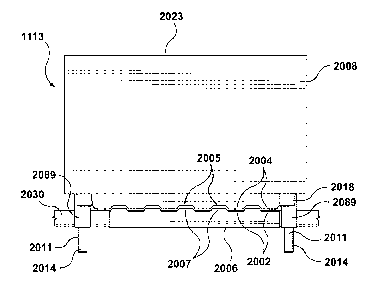
between (a) a first
(retracted) position (Figure 14A) where thc engagement surface 2023 is a first
distance D1 from
the surface 2143 of the cavity plate 1110 and (b) a second (extended) position
(Figure 1413)
where the engagement surface 2023 is positioned a second distance D2 spaced
away from the
front of surface 2143 of cavity plate 1110. In the retracted position, tonnage
block 1113 may be
at least partially received in an aperture in wear plate 1119 and a gap may be
left between
engagement surface 2023 and stripper plate 1117. With tonnage block 1113 in
this position, the
distance between the opposing surfaces of the stripper plate 1117 and cavity
plate 1110 is
defined by the mold stack 1111 and the regular tonnage blocks 1118, and D1
(i.e. the distance
between the engagement surface 2023 of the tonnage block 1118 and the surface
2143 of the
cavity plate 1110 in the retracted position) is no more, and possibly is less,
than the height of the
regular tonnage blocks 1118. In the extended position, tonnage block 1113 is
fully received in an
aperture in wear plate 1119 and the engagement surface 2023 of engagement
portion 2008 is in
abutment with the surface 2119 of the stripper plate 1117. But distance D2
(i.e. the distance
between the engagement surface 2023 of the tonnage block 1118 and the surface
2143 of the
cavity plate 1110 in the extended position) is greater than D1 and the height
of regular tonnage
blocks 1118 and thus the distance between the opposing surfaces of the cavity
plate 1110 and the
stripper plate 1117 is increased by extension of the adaptive tonnage blocks
1113. Thus the
height H and corresponding mold shut height S can be increased.
[0085] When the engagement surface 2023 is at the first (retracted) position
(Figure 14A) the
injection mold 1100 may be in its standard mold operating configuration. When
the engagement
surface 2023 of the adaptive tonnage block 1113 is in its second (extended)
position (Figure
14B), the injection mold 1100 may be in an alternate operational configuration
such as for
example the vent cleaning operational configuration. The movement of the
adaptive tonnage
blocks 1113 may be coordinated with the movement of core plate adjustment
mechanism 3000
and neck ring adjustment mechanism 4000 as described above.
[0086] With particular reference to Figures 12, 13, 14A and 14B, in addition
to engagement
portions 2008 and separation blocks 2118, each adaptive tonnage block 1113 may
have a driving
portion 2006 which is moveable with sliding motion in a direction parallel to
the Z axis between
first and second positions. The driving portion 2006 may be received with
apertures 2016 in the
cavity plate 1110 and driving portion 2006 has a surface 2033 which rests
against an adjacent
surface of the cavity plate 1110 in the apertures 2016 in the cavity plate.
Thus, a load on the
17
CA 2901398 2017-06-28
H-7688-1 -CA
driving portion 2006 acting in the direction parallel to axis X towards the
cavity plate 1110 can
be transmitted to the cavity plate 1110. In the first position (shown in
Figures 12 and 14A),
upper protrusions 2007 on the surface of driving portion 2006 are received in
recesses 2005 on
the rear surface of the separation block 2018.
[0087] Similarly, in such a position, the recesses 2002 on driving portion
2006 may receive
protrusions 2004 on the separation block 2018. In such a position, all the
protrusions may not
engage or at least are in such a position that the engagement portion 2008 is
in its first position
referenced above. Driving portion 2006 may be moved from the position shown in
Figures 12
and 14A in a direction parallel to axis Z to a position shown in Figure 14B
where upper
protrusions 2007 on its surface cam against the protrusions 2004 on the
adjacent surface of the
separation block 2018 and move the separation block 2018 along with engagement
portion 2008
to a position where the protrusions 2007 are generally aligned with
protrusions 2004 in the Z
direction. This has the effect of causing the engagement portions 2008 to move
outwardly in a
direction parallel to the X axis. In this position an additional separation
distance will be created
between the opposed surface 2143 of cavity plate 1103 and the surface 2119 of
stripper plate
1117.
[0088] The movement of engagement portion 2008 and separation block 2018 is
limited to the
aforementioned back and forward movements parallel to the X axis. This limited
movement
may be accomplished in many ways. For example, a pair of spaced pin members
2011 (Figure
13) may be provided proximate opposed ends of the engagement portion 2006
having shafts that
are generally axially aligned with axis X. The shafts of pins 2011 may have
bottom threaded end
portions 2014 that pass through the engagement portion 2008, separation block
2018 and driving
portion 2006 of adaptive tonnage blocks 1113 and are received in corresponding
threaded
apertures in the cavity plate 1110. Thus the pins 2011 secure the adaptive
tonnage blocks 1113
to the cavity plate 1110. Shafts of pins 2011 may also have upper portions
that at their upper end
are integrally connected with heads 2009. Each pin 3011 may be received
through a generally
cylindrical sleeve tube 2089 that may be itself be housed in a generally
cylindrical pad aperture
2017 that passes entirely through engagement portion 2008. The sleeve 2089 may
also be housed
within and pass through an aligned aperture in separation block 2018. Below
each pin head 2009
of pin 2011 is a shoulder portion 2069 and beneath the shoulder 2069 is a
spring 2099 which
engages and is retained in compression between shoulder 2069 and separation
block 2018.
Spring 2099 may fit around the outer surface of sleeve 2089. Engagement
portion 2008 and
separation block 2018 may slide up and down relative to sleeve 2089. Thus,
whcn engagement
portion 2008 and separation block are moved by driving portion 2006, there
will be a restoring
force exerted by the spring 2099 as it is held between the shoulder 2069 and
separation block
18
CA 2901398 2017-06-28
H-7688-1-CA
2018. It will be appreciated that the engagement portion 2008 may move in a
direction parallel
to axis X as the apertures slide over pins 2011 between an extended position,
and a retracted
position where the protrusions 2004 of the separation block 2018 are
transversely aligned and in
abutment with the recesses 2002 of the driving portion 2006 (i.e. the
engagement portion 2008 is
fully retracted).
[0089] With particular reference now to Figures 11A and 12 it can be observed
that to cause
driving portion 2006 to be driven in reciprocating movement in a direction
parallel to axis Z,
driving portion 2006 may be secured to a connecting rod 2030 that generally
runs in a direction
parallel to axis Z. Driving portion 2006 may be secured to connecting rod 2030
by interlocking
teeth 2121 (Figure 11C) or by other suitable methods such as by way of example
welding or
bolting. Engagement portion 2008, separation block 2018 and driving portion
2006 may be made
of any suitable material such as by way of example stainless steel. Similarly,
connecting rods
2030 may be made from any suitable material such as by way of example a heat-
treated steel. A
single rod 2030 may be attached to driving portions 2006 of one or more
aligned back up pad
devices 3001. For example, the rod 2030 depicted in the cross sectional view
of Figure 11B is
attached to four driving portions 2006 of separate adaptive tonnage blocks
1113.
[0090] A plurality of connecting rods 2030 may be provided so that the driving
portion 2006 of
each adaptive tonnage block 1113 in the cavity plate 1110 may be connected to
at least one
connecting rod 2030. The plurality of connecting rods 2030, which all may be
aligned in a
direction parallel to axis Z, may be themselves be all interconnected by any
known and suitable
attachment mechanism such as bolting, welding etc. to a common actuator cross
bar 2035 that
may be made from any suitable material such as by way of example only
stainless steel.
[0091] Actuator cross bar 2035 may be oriented in a direction generally
orthogonal to the
connecting rods and generally parallel to axis Y. Thus connecting rods 2030
and actuating bar
2035 may together constitute a connection mechanism to connect the driving
portion 2006 with
an actuator. Connecting rods 2030 may in some embodiments such as is
illustrated in Figure 10
and 11A be housed and moveable within enclosed channels that extend within the
body of the
cavity plate 1110, and thus will be generally not be visible when looking at
the cavity plate such
as in the view shown in Figure 7. In other embodiments, the connecting rods
2030 may be
housed and moveable within open channels where the channels are formed as
longitudinally
extending grooves defined in the cavity plate and at the inward facing surface
of cavity plate
1110.
[0092] Actuator bar 2035 may in turn be secured in a suitable manner to an
actuating device
2045 (Figure 11A) such as a servo motor, pneumatic piston, under the control
of controller 3050.
Actuating device 2045 may have an actuating shaft (not shown) capable of
providing
19
CA 2901398 2017-06-28
H-7688-1-CA
intermittent, controlled, reciprocating movement back and forth in directions
that are generally
parallel to axis Z. Actuating device 2045 may thus have communication link to
the controller
3050. Actuating device 2045 may be mounted within the cavity plate 1110 with
screws
connecting it to the cavity plate 1110. By means of the interconnection of
actuating device 2045
and its reciprocating shaft interconnected to actuating cross bar 2035, which
in turn is connected
to each of the connecting rods 2030, which in turn are interconnected to
driving portions 2006 of
adaptive tonnage blocks 1113, cyclical, controlled and intermittent movement
of the actuating
shaft of the actuating device 2045, may result in synchronized movement of
each driving
portions 2006 in a direction parallel to axis Z, and thus the synchronized
movement of all
engagement portions 2008 in the direction parallel to axis X. By way of
example only, actuator
shaft of actuating device 2045 may be moved about 10mm in a direction parallel
to axis Z,
resulting in a corresponding movement parallel to the Z axis of the connecting
rods 2030 and the
driving portions 2006 of the back up pad devices 3001. The engagement of
driving portions
2006 with separation blocks 2018 and thus engagement portions 2008 may
translate into 0.5mm
movement of the engagement portions 2008 in a direction parallel to axis X to
result in an
increase in separation of 0.5mm separation between the opposed surfaces of the
cavity plate
1110 and the stripper plate 1117. Under the control of controller 3050, this
may occur in a
coordinated fashion with the movement of neck ring halves 1114a, 1114b in a
direction parallel
to the Y-axis and the movement of back up pads 3001 in a direction parallel to
the X-axis.
[00931 During normal molding use, core plate 1103 and cavity plate 1110 will
be cycled to a
closed position as shown in Figure 14 with the mold stack therebetween
providing a first
operational configuration for the mold 1100. While in this position, the mold
stack 1111 is
subjected to compressive clamping force A (Figure 2A) as mold material is
injected and then
cooled and hardened. Subsequent to cooling of parts, the stack is moved from
its normal
operational configuration and cycled to its open position (Figure 15), in
which the clamping
force is released and the core and cavity plates are spread longitudinally
relatively apart, thus
taking on a non-operational configuration (i.e. the mold is not in a
configuration where it is
being operated to inject mold material into the mold cavities). In the mold
open configuration,
finished parts are ejected in a conventional manner as the stripper plate 1117
slides away from
the core plate 1103 and, slide bars 1115a, 1115b and neck ring halves 1114a,
1114b are moved
laterally outwardly to the position shown in Figure 15. During this normal
operation, vents in
neck ring halves 1114a, 1114b may function substantially to permit gas to
escape, but prevent
substantial quantities of injected mold material from entering the vents. In
such normal
operation, in order for the mold stack to close to the desired molding
configuration, each of the
cavity plate adjustment mechanism 2000 and core plate adjustment mechanism
3000 operate in
CA 2901398 2017-06-28
H-7688-1-CA
their first (retracted) conditions, and neck ring adjustment mechanism 4000
operates in its first
(normal) condition as described above. The positions of the mold stack
components in the closed
state of this normal molding operation are as depicted in Figure 2A.
[0094] Periodically, it may be desired to place the mold 1100 in an alternate
operational
configuration, such as an operational configuration which can clean vents as
described above. As
will be appreciated from the foregoing description, cleaning may entail
providing additional
clearance between neck ring halves 1114a, 1114b to increase vent size. At the
beginning of a
cleaning cycle, the mold 1100 may be open as shown in Figure 15. Actuating
device 3045 may
then be cycled to cause back up pads 3001 to be extended, which will result in
core plate 1103
being spaced apart from stripper plate 1117 and the neck ring halves 1114a,
1114b. As noted,
cycling of actuating device 3045 also causes movement of actuating blocks 4010
so that thrust
pad devices 4012a, 4012b push the slide bars 1115a, 1115b and therefore the
neck ring halves
1114a, 1114b apart. Meanwhile, actuating device 2045 may cause adaptive
tonnage blocks 1113
to be extended, which in turn causes cavity plate 1110 and stripper plate 1117
to have an
increased spacing apart from one another. As will now be appreciated, this
provides lateral
clearance permitting the neck ring halves 1114a, 1114b to be held spaced
apart. The mold may
then be closed, by appropriate relative movement between the cavity plate 1110
and the wear
plate 1119, stripper plate 1117 and core plate 1103, but without application
of any significant
clamping force A.
[0095] In this alternate (cleaning) operational configuration, the components
of the mold stack
are positioned as shown in Figure 16 when the mold stack is closed. In this
condition, an
enlarged gap exists between the neck ring halves. Once the mold components are
in this
configuration, clamping force A may be applied. In some embodiments, clamping
force A may
be reduced relative to the clamping force that is applied during normal
molding operation. In
other embodiments, the clamping force could be the same or even greater than
in the normal
operational mode. This might be required because the molding material is
acting on a larger
surface area of the components. Molding material is then injected and cooled
and molded parts
are ejected substantially as described above. Due to the spacing apart of neck
ring halves 1114a,
1114b during molding, molding material occupies the enlarged vents which may
have the effect
of removing residue from the vents. This may also result in excess flash
material on finished
parts. Such parts may therefore be discarded.
[0096] In other embodiments, cycling of actuating device 3045 and actuating
device 2045 may
occur with the mold in the position depicted in Figure 16 - that is with the
mold closed. In such a
case, mold components may be pushed to their alternate (cleaning)
configurations with cavity
plate adjustment mechanism 2000, core plate adjustment mechanism 3000 and neck
ring
21
CA 2901398 2017-06-28
H-7688-1-CA
adjustment mechanism 4000 being operated so that the components adopt their
alternate
configurations.
[0097] In other embodiments, the cavity plate adjustment mechanism, core plate
adjustment
mechanism and the neck ring adjustment mechanism may he used alone or in
combination to
selectively create spacing between mold stack components for reasons other
than vent cleaning.
In some embodiments, all or some of core plate adjustment devices 3001 and
cavity plate
adjustment devices 2001 could be provided with individual activation instead
of having
connectors like 2030 or 3030. Individual activation could be done by hydraulic
and/ or
pneumatic device (cylinder) or by servo drives (electrical).
[0098] As an alternative, or even in addition, to employing the mold shut
height adjustment
apparatus described herein for vent cleaning, the apparatus may also be used
to implement the
method described in commonly assigned US patent publication 2012/0219651 to
Weber et al.,
published on August 30, 2012. Specifically, the present non-limiting
embodiments of the mold
shut height adjustment apparatus may be useful in implementing a pressure-
control system in an
injection mold for selectively changing a volume of a mold cavity defined
within the mold after
isolation thereof from a stream of molding material. A technical effect
attributable to the
foregoing may include, amongst others, providing a pre-eject function while
maintaining contact
between the molded article and the molding surfaces of the mold cavity.
[0099] It should be understood that for the purposes of the description
provided above and
claims presented below, the term "fluid", "gas" or "air" are meant to denote
fluid present in the
molding cavity and being vented from the molding cavity and the molding
material fills in the
molding cavity. The terms "fluid", "gas" or "air" can denote ambient air
around the molding
system, as well as the ambient air mixed in with other substances potentially
present within the
molding system.
[00100] The description of the embodiments of the present inventions
provides examples
of the present invention, and these examples do not limit the scope of the
present invention. It is
to be expressly understood that the scope of the present invention is limited
by the claims only.
The concepts described above may be adapted for specific conditions and/or
functions, and may
be further extended to a variety of other applications that are within the
scope of the present
invention. Having thus described the embodiments of the present invention, it
will be apparent
that modifications and enhancements are possible without departing from the
concepts as
described. Therefore, what is to be protected by way of letters patent are
limited only by the
scope of the following claims:
22
CA 2901398 2017-06-28